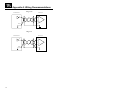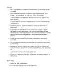
1
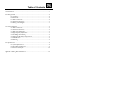
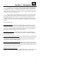
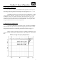
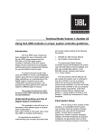
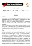
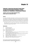
Linear Spatial Reference
LSR25P Studio Monitor System
Preliminary Owner’s Manual
1
Important Safety Precautions
Explanation of Graphic Symbols
The exclamation point within an equilateral triangle is intended
to alert the users to the presence of important operating and
maintenance (servicing) instructions in the literature accompanying the product.
The lightning flash with the arrowhead symbol, within an equilateral triangle, is intended to alert the user to the presence of
insulated “dangerous voltage” within the product’s enclosure
that may be of sufficient magnitude to constitute a risk of electric shock to humans.
CAUTION
DO NOT EXPOSE
TO RAIN OR MOISTURE!
ATTENTION
NE PAS EXPOSER Á
LA PLUIE NI Á L'HUMIDITÉ!
CAUTION: TO REDUCE THE RISK OF ELECTRIC SHOCK
DO NOT REMOVE COVER.
NO USER SERVICEABLE PARTS INSIDE.
REFER SERVICING TO QUALIFIED PERSONNEL.
ATTENTION: POUR EVITER LES RISQUES DE CHOC
ELECTRIQUE, NE PAS ENLEVER LE COUVERCLE. AUCUN
ENTRETIEN DE PIECES INTERIEURES PAR L’USAGER. CONFIER L’ENTRETIEN AU PERSONNEL QUALIFIE. AVIS: POUR
EVITER LES RISQUES D’INCENDIE OU D’ELECTROCUTION,
N’EXPOSEZ PAS CET ARTICLE A LA PLUIE OU
A L’HUMIDITE.
The IEC fuse symbol pictured at the left represents an approved,
user replaceable fuse. When replacing a fuse, make sure to
replace with only the correct type and fuse rating.
1. Read Instructions – Before operating your new JBL LSR product, please read all safety
and operating instructions.
2. Keep these instructions – For future reference and troubleshooting purposes, retain
these instructions.
3. Heed all warnings – All warnings in this user manual should be followed.
4. Follow Instructions – By following instructions presented in this guide, you should be
able to quickly enjoy an accurate and safe monitoring system.
5. Water and Moisture – Do not use this apparatus near water – for example, bathtub,
sink or in the shower, regardless of how well you sing.
2
Important Safety Precautions
6. Cleaning – Clean with a lint free cloth-Do not use any solvent based cleaners. A slightly
damp cloth can also be used on the enclosure surfaces and woofer surrounds.
7. Ventilation – Do not block any ventilation opening, including the Linear Dynamics
Aperture Port on the LSR monitor systems, by installing these products in accordance with
manufacturers instructions. Do not install near any heat sources such as radiators, heat
registers, stoves or other apparatus that produce heat.
8. Grounding and Power Cords – The power cord supplied with your powered LSR product has a 3-pin type plug. Do not cut off or damage the grounding pin and once again,
don’t use in a shower. If the provided plug does not fit into your outlet, consult an electrician for replacement of the obsolete outlet. Protect the power cord from being walked on,
or pinched, particularly at plugs, convenience receptacles and the point where they exit the
apparatus.
All powered LSR products are fitted with a detachable power cord (supplied) which connects to the chassis AC connector. The power cord has an IEC female connector on one end
and a male mains connector on the other end. This cord is supplied specifically to accommodate the different safety and electrical code requirements of individual countries. If you
are traveling abroad with your system, test the power mains and be aware of any specific
voltage requirements before operating your system.
9. Options – Only use attachments or accessories specified by the manufacturer.
10. Non-use Periods – Unplug this apparatus during lightning storms, earthquakes, fires,
floods, locusts, or when unused for long periods of time.
11. Servicing – Refer all servicing to qualified service personnel. Servicing is required
when the apparatus has been damaged in any way, such as power supply cord or plug is
damaged, liquid has been spilled, or objects have fallen into the LSR monitor, the monitor
has been exposed to rain or moisture, does not operate normally, exhibits signs of schizophrenia or other psychosis, or has been dropped.
12. Wall or Ceiling Mounting – The appliance should be mounted to a wall or ceiling
only as recommended by the manufacturer.
13. Carts and Stands – The appliance should be used only with a cart or stand that is recommended by the manufacturer. An appliance and cart combination should be moved
with care. Quick stops, excessive force, and uneven surfaces may cause the appliance and
cart combination to overturn.
The information contained in this document is
confidential and the copyright of JBL Professional. To
convey its contents, in part or in whole to any third party
without prior written authorization is a violation of the
copyright. © JBL Professional 2000.
3
Table of Contents
1.0 Introduction ................................................................................................................1
2.0 Getting Started ............................................................................................................2
2.1 Unpacking ..................................................................................................2
2.2 Placement ..................................................................................................2
2.3 Audio Connections ....................................................................................2
2.4 AC Power Connections ..............................................................................3
2.5 Making Sound Happen ..............................................................................3
3.0 General Operation......................................................................................................4
3.1 Audio Connections ....................................................................................4
3.2 AC Power Connections ..............................................................................4
3.3 Audio Level Adjustment..............................................................................5
3.4 High Frequency Adjustments ....................................................................5
3.5 80 Hz High Pass Filtering ..........................................................................6
3.6 Workstation Boundary Compensation ......................................................6
3.7 LED Indication ..........................................................................................6
3.8 Mounting....................................................................................................6
4.0 Specifications ............................................................................................................8
4.1 System Specifications ................................................................................8
4.2 Transducer Specifications ..........................................................................9
4.3 Performance Graphs ................................................................................10
Appendix A: Wiring Recommendations ........................................................................12
4
5
Section 1: Introduction
Congratulations on selecting the LSR Linear Spatial Reference Studio Monitors.
They represent the sum total of our research and development efforts in sound reproduction. While we don’t expect you to read the entire manual, we do suggest section 2 to get
started. At that time, you should have a system to listen to while you intensely study the rest
of the manual for maximum performance.
Beginning with a blank CAD screen, today’s equivalent to a clean sheet of paper,
the LSR products have been based on fundamental research into all aspects of monitor
design. JBL designed the entire system starting with the materials and topologies of the
individual transducers, through to the final assembly of the diecast parts. The results are
incredibly accurate reference systems with high dynamic capabilities and astonishingly low
distortion.
New LSR Technologies
Linear Spatial Reference A measurement and design philosophy that takes into account
many additional factors beyond on-axis frequency response. The overall performance of
the systems are optimized within a wide listening window for exceptional performance in a
variety of acoustic spaces. Attention to these critical aspects results in a rock solid image
that remains consistent throughout the entire listening field.
Linear Dynamics Aperture™ Contoured ports virtually eliminate high-end turbulence
found in traditional port designs. This provides more accurate low frequency performance
at higher output levels.
Titanium Composite High Frequency Device Using patented technology, the high frequency
device incorporates titanium and composite materials to improve transient response and
reduce distortion. By reducing distortion in the lower operating range, where the ear is
most sensitive, ear fatigue is radically reduced.
Elliptical Oblate Spheroidal (EOS) Waveguide Designed for a targeted listening window of
+/- 30˚ horizontally and +/- 15˚ vertically, the EOS provides a frequency response through
the entire window of 1.5 dB from on-axis. This allows listeners, even far off-axis to hear an
accurate representation of the on-axis response.
Workstation Boundary Compensation
Low and mid frequencies can be adjusted to optimize performance where boundaries such
as video monitors and desktop surfaces are present in the monitoring environment.
1
Section 2: Getting Started
2.1 Unpacking:
An easy way to safely unpack your monitors is to open the top of the box, keep
the filler piece on, and roll the box upside down. The box can then be slipped off. This also
works in reverse for repacking the units to take them to the next session.
2.2 Placement:
The design of the LSR systems lend themselves to a wide variety of placement
options. Covered here is a typical stereo setup for near to mid field monitoring. A deeper
discussion of multi-channel sound setup is available from JBL in Tech Note Volume 3,
Number 3.
Listening Distance: By evaluating a broad cross-section of studio environments, it was determined that the common listening position at recording consoles is generally 1 to 1.5 meters (3 to 5 feet) for near field applications. For mid-field applications, 2
to 3 meters is more likely. The real key to successful stereo placement is to form an equilateral triangle between the monitors and the prime listening position. As shown below, the
distance between the monitors and the distance between each monitor and the center of
the listener’s head are equivalent.
Vertical vs. Horizontal Placement: The LSR25P near field is designed to
be positioned vertically. This orientation eliminates the phase shifts that occur when the
relative distances between the woofer, tweeter and the listening position change.
Angling towards the listening position: LSR monitors should be angled
to directly face the listener. The center of the high frequency transducer should be on-axis
with the ear level of the listener.
2.3 Audio Connections:
LSR25P Audio Connections: The LSR25P comes with an XLR and RCA connectors to accommodate a wide range of signal levels and balanced or unbalanced configurations. The XLR input is nominal +4 dBu sensitivity and the RCA input is -10 dBV.
Variable user calibration can also be accommodated using the front mounted volume control. Positive voltage applied to Pin 2 of the XLR or the pin of the RCA jack will produce a
forward motion in the low frequency cone.
2
Section 2: Getting Started
2.4 AC Power Connections:
The LSR25P has power transformers which allow them to be used with multiple
AC supply voltages around the world. Before connecting the unit to AC power, confirm that
the switch setting on the rear of the unit is set to the proper position and the fuse is the correct rating. The LSR25P will accept voltages from 100-120 or 200-240 Volts, 50-60 Hz when
the voltage setting and fuse is correct. The ground terminal of the IEC plug is required by
wiring codes and regulations. It must always be connected to the electrical installation
safety ground. The LSR units have carefully designed internal grounding and balanced
inputs and outputs to reduce the possibility of ground loops (hum). If hum occurs, see
Appendix A for suggested audio signal wiring and system grounding.
2.5 Making Sound Happen:
After connections are made, the next step is to power up all equipment before the
amplified LSR25P monitors. Reduce the level of the monitor outputs of your console or
preamp and also turn the volume on the front of the LSR25P monitors fully counter clockwise for minimum gain. You can now turn on the monitors. There is a small delay with
the turn on to accommodate for clicks and thumps from upstream equipment. When the
Green LED on the front panel turns on, the units are ready to go. Slowly advance the gain
of the LSR25P monitors and check for hum or noise. If everything is correct, advance the
the console to feed the monitoring system and sit back and enjoy. If there is excessive
hum, noise or no signal see Appendix A on suggested wiring practices.
3
Section 3: General Operation
3.0 Introduction:
The LSR25P Bi-amplified reference monitor sets a new standard for exceptional
performance in a compact near field design. Using a combination of advanced transducer
engineering and powerful drive electronics, the LSR25P will stand up to the most demanding sessions.
The 5.25” woofer is based on JBL’s Symetrical Field Geometry (SFG)® technology.
With a massive 1.5” drive coil, excursion capability is maximized while retaining excellent
distortion performance. The heavy magnetic structure keeps power compression to a minimum to reduce spectral shift as power levels increase. The tempered paper cone forms a
rigid piston and is supported by a soft butyl rubber surround. The entire driver is shielded
for use near video monitors and other equipment sensitive to magnetic fields.
The high frequency device is a 1" composite diaphragm integrated with an
Elliptical Oblate Spheroidal (EOS) Waveguide with 100 x 60 degree dispersion which is
critical to the smooth spatial response required in today’s working environments. The
design, as with the woofer above, is shielded.
3.1 Audio Connections:
The LSR25P comes with an XLR and RCA connectors to accommodate a wide
range of signal levels and balanced or unbalanced configurations. The XLR input is nominal +4 dBu sensitivity and the RCA input is -10 dBV. Variable user calibration can also be
accommodated using the front mounted volume control. Positive voltage to Pin 2 of the
XLR or the pin of the RCA jack will produce a forward motion in the low frequency cone.
3.2 AC Power Connections:
The LSR25P has power transformers which allow them to be used with multiple
AC supply voltages around the world. Before connecting the unit to AC power, confirm that
the switch setting on the rear of the unit is set to the proper position and the fuse is the correct rating. The LSR25P will accept voltages from 100-120 or 200-240 Volts, 50-60 Hz when
the voltage setting and fuse is correct. The ground terminal of the IEC plug is required by
wiring codes and regulations. It must always be connected to the electrical installation
safety ground. The LSR units have carefully designed internal grounding and balanced
inputs and outputs to reduce the possibility of ground loops (hum). If hum occurs, see
Appendix A for suggested audio signal wiring and system grounding.
4
Section 3: General Operation
3.3 Audio Level Adjustment:
The audio level sensitivity of the LSR25P can be adjusted for almost any situation. Monitor outputs on consoles are normally at a nominal level of +4 dBu or -10 dBv.
These are typically called professional and semiprofessional, respectively.
As shipped from the factory, the nominal input level of the XLR input is +4 dBu
and -10 dBv for the RCA input. A nominal level to these inputs will produce an output of
96 dB SPL at 1 meter in an anechoic environment. This allows the user to get a good
match when using either professional or semiprofessional equipment. If less sensitivity is
needed the front channel volume control can be adjusted down. The front panel adjustment gives 9 dB of attenuation in the 12 o’clock position.
3.4 High Frequency Adjustments:
A group of four DIP switches are located in a recess on the back of the LSR25P.
These allow the user to adjust various aspects of the frequency response. Switch 3 boosts
the high frequency response by 1.5 dB above 2.3 kHz when moved into the up position.
This position is used if the room is extremely dead or mixes translate too bright.
Switch 4 cuts the high frequency response by 1.5 dB above 2.3 kHz when moved
into the up position. This position is used if the room is highly reflective or mixes translate
dull.
Effects of High Frequency Adjustments
Switch 3 On +1.5 dB
Switch 3 & 4 Off Flat
Switch 4 On -1.5 dB
5
Section 3: General Operation
3.5 80 Hz High Pass For Use With Subwoofers:
The Low Frequency cut off can be adjusted to either 40 Hz or 80 Hz. This
allows easy use of powered subwoofers without requiring complicated cabling or
loop throughs. Switch 1 selects the 80 Hz setting when in the up position.
3.6 Workstation Boundary Compensation:
The bass and low mid frequency response of the LSR25P can be adjusted to compensate when the system is located near a wall or other boundary surface.
3.7 LED Indication:
A single Bi-Color LED indicator is located on the front of the LSR25P. In normal
operation, this LED will be GREEN. At the onset of amplifier clipping in either the low or
high frequency amplifier, the LED will flash RED. Continual RED flashing of this LED
indicates that levels should be reduced.
3.8 Mounting:
The LSR25P has built in mounting point for use with Omnimount® 75 Series
brackets. These are located on the upper back of the cabinet. The threaded holes accept a
1/4” diameter machine screw with a pitch of 20 threads per inch.
6
Section 3: General Operation
7
Section 4: Specifications
System:
Frequency Response (+1, -2 dB):
Enclosure Resonance Frequency:
Low Frequency Extension:
-3 dB:
-6 dB:
-10 dB:
Low - High Frequency Crossover:
Distortion, 96 dB SPL, 1m:
Mid-High Frequency (150 Hz - 20 kHz):
2nd Harmonic:
3rd Harmonic:
Low Frequency (<150 Hz):
2nd Harmonic:
3rd Harmonic:
Maximum SPL (90 Hz - 20 kHz):
Maximum Peak SPL (90 Hz - 20 kHz):
Signal Input:
Calibrated Input Sensitivity:
XLR, +4 dBu:
RCA, -10 dBV:
AC Input Voltage:
AC Input Voltage Operating Range:
AC Input Connector:
Long Term Maximum System Power:
Self Generated Noise Level:
User Controls:
High Frequency Control (3 kHz - 20 kHz):
Workstation Boundary Compensation:
Low Frequency Alignment:
LSR25P
70 Hz - 20 kHz
55 Hz
User controls set to default
65 Hz
56 Hz
48 Hz
2.3 kHz
4th-Order Electroacoustic Linkwitz-Riley
<0.5%
<0.5%
<2%
<3%
>106 dB SPL / 1 m
>109 dB SPL / 1 m
XLR, Balanced
RCA, Unbalanced
Positive voltage applied to XLR Pin 2 (RCA tip)
produces outward woofer motion.
96 dB/1 m
96 dB/1 m
115/230 VAC, 50/60 Hz (User Selectable)
+/- 15%
IEC
110 Watts (IEC265-5)
<10 dBA SPL/1 m
+1.5 dB, 0 dB, -1.5 dB
Active or Bypass
36 dB/Octave Butterworth hi pass at 40 Hz
36 dB/Octave Bessel hi-pass at 80 Hz
(For use with Subwoofer)
Variable Input Attenuation: 0 - 26 dB (9 dB at 12 o’clock)
Amplifiers:
Low Frequency:
Topology:
Sine Wave Power Rating:
THD+N, 1/2 power:
High Frequency:
Topology:
Sine Wave Power Rating:
THD+N, 1/2 power:
8
Bridged Class A-B Monolithic
100 Watts (<0.1% THD into rated impedance)
<0.05%
Class A-B, Monolithic
50 watts (<0.1% THD into rated impedance)
<0.05%
Section 4: Specifications
Transducers:
Low Frequency Diameter:
Voice Coil:
Magnet Type:
Cone Type:
Nominal Impedance:
High Frequency Diameter:
Voice Coil:
Magnet Type:
Diaphragm Type:
Other Features:
Nominal Impedance:
134 mm (5.25 in.)
38 mm (1.5 in.)
Ferrite with Integral Shielding
Tempered Paper with Butyl Rubber Surround
8 ohm
25 mm (1 in.) diaphragm
25 mm (1 in.)
Ferrite with Integral Shielding
Damped Titanium Composite
Elliptical Oblate Spheroidal Waveguide
4 ohms
Finish:
Grille:
Enclosure Volume (net):
Low Frequency Vent:
Gray
Black Steel Perforated
6.5 cu. liter (0.2 cu. ft.)
Dual Front Ported Linear Dynamics Aperture
(Integrated with die-cast baffle)
Powder Coated Diecast Aluminum
Powder Coated Diecast Aluminum
7.7 kg (17 lbs)
17.3 x 26.9 x 24.1 cm (6.8 x 10.6 x 9.5 in)
Physical:
Baffle Construction:
Cabinet Construction:
Net Weight:
Dimensions (WxHxD):
Notes:
All measurements unless otherwise stated made anechoically in a 4π environment at 2 meters and referenced to 1 meter by the inverse square law.
The reference measurement microphone position is located perpendicular to the
centerline of the low and high frequency transducers, at the point 70 mm (2.7
in.) above the center of the woofer.
Acoustic loading provided by the listening room increases Maximum SPL capabilities and Low Frequency Bass Extension as compared to stated anechoic values.
Distortion measurements performed with the input voltage necessary to produce
the stated “A” weighted SPL level at the stated measurement distance. Distortion
figures refer to the maximum distortion measured in any 1/10th octave wide
band in the stated frequency range.
JBL continually engages in research related to product improvement. New materials, production methods, and design refinements are introduced into existing
products without notice as a routine expression of that philosophy. For this reason, any current JBL product may differ in some respect from its published
description, but will always equal or exceed the original design specifications
unless otherwise stated.
9
Section 4: Specifications
Amplitude and Phase
J
o ess o a
100
200
100
-100
SPL
-200
Phase
0
90
-300
80
-400
dB
-500
-600
70
-700
-800
-900
60
-1000
20
100
1000
Frequency
Hz
10000
Hz
10000
20K
96 dB/1 m (Distortion raised 20 dB)
J
o ess o a
100
SPL
90
2nd Harmonic
80
dB
3rd Harmonic
70
60
20
100
Frequency
1000
20K
40
90
30
SPL
100
20
dB
80
70
10
60
20
10
100
Frequency
1000
Hz
10000
0
20K
Directivity (dB)
LSR25P Response Curves
Section 4: Specifications
11
Appendix A: Wiring Recommendations
By now, you have probably plugged the LSR monitors in and are making great
music. However, for optimum performance, some attention to wiring details now can
reduce system degradation later. These cabling recommendations follow standard wiring
practice for balanced and unbalanced inputs.
Balanced Sources
The best way to run your system is balanced, where both “HOT” (+) and
“COLD” (-) signals are supplied, as well as a GROUND/SHIELD. These are typically carried on 2 conductor shielded cables with XLR connectors on both ends. Whenever possible,
the cable shield should not be connected to any signal pin, but left to perform a cable
shielding function only.
Note: Under no circumstances should the safety ground wire be removed from the AC
power connector.
When using balanced sources with the LSR25P, it is recommended to use the
XLR input on the LSR25P. This maintains a balanced signal and is the best way to reduce
the possibility of hum or other interference
For balanced sources, the HOT (+) signal from your source should be connected
to Pin 2 of the XLR input as shown in Diagram A. The “COLD” (-) signal should be connected to Pin 3 of the XLR. To avoid ground loops, connect the SHIELD at the source end
but not at the LSR input.
Diagram A
Balanced Source
LSR25P XLR Input
+
Pin 2
(Tip)
Pin 2
+
-
Pin 3
Pin 3
(Ring)
-
Pin 1
Pin 1
(Sleeve)
The LSR25P was designed to output a level of 96 dB SPL at 1 meter with a
+4 dBu signal applied to the XLR input. If additional gain is required from a balanced
output, Diagram B can be used with the RCA input. The sensitivity of the RCA input is
approximetly 12 dB higher than the XLR input.
12
Appendix A: Wiring Recommendations
Diagram B
Balanced Source
LSR25P RCA Input
+
Pin 2
(Tip)
-
(Ring)
Tip
+
Pin 3
Pin 1
Sleeve
(Sleeve)
Unbalanced Sources:
Consumer and semi-professional equipment with unbalanced signals usually
have a lower output capability than professional devices. In these cases, it is recommended
to use the LSR25P RCA input. This input has been specifically designed to accommodate
the lower output levels typical of consumer and semi-professional equipment. Figure C
shows when using the RCA connection.
Diagram C
Unbalanced Source
+
Tip
Sleeve
LSR RCA Input
Tip
+
Sleeve
While there are only HOT and GROUND/SHIELD connections from unbalanced
sources, it is recommended that high quality twisted pair cable be used when using the
XLR input of the LSR25P. Diagram D shows an unbalanced source connected to the balanced XLR input of the LSR monitor using twisted pair cable. Note that the shield is connected to the GROUND/SHIELD connector at the LSR input, but not at the source. This
reduces the likelihood of introducing a ground loop into the system.
Diagram D and E are similar. In Diagram E, a link is added between Pin 3 and Pin 2 of
the XLR connector. In some cases, this could be required if hum is encountered.
13
Appendix A: Wiring Recommendations
Diagram D
Unbalanced Source
+
LSR XLR Input
Tip
Sleeve
Pin 2
+
Pin 3
-
Pin 1
Diagram E
Unbalanced Source
+
Tip
Sleeve
14
LSR XLR Input
Pin 2
+
Pin 3
-
Pin 1
JBL Professional
8500 Balboa Boulevard, P.O. Box 2200
Northridge, California 91329 U.S.A.
www.jblpro.com
A Harman International Company
LSR25P MANUAL
98100056-00
CRP 1M
11/99