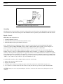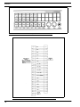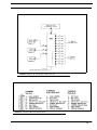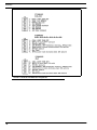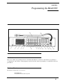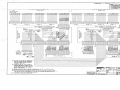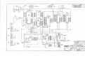
1
Technical Data Package
Models 802 and 802A
Master Station
9300-3510-00 Rev F
5/2006
SHIPPING TO THE MANUFACTURER
PROPRIETARY NOTICE
The product information and design disclosed herein were originated by
and are the property of Telex Communications, Inc. Telex reserves all
patent, proprietary design, manufacturing, reproduction, use and sales
rights thereto, and to any article disclosed therein, except to the extent
rights are expressly granted to others.
COPYRIGHT NOTICE
Copyright 2006 by Telex Communications, Inc. All rights reserved.
Reproduction, in whole or in part, without prior written permission from
Telex is prohibited.
WARRANTY NOTICE
See the enclosed warranty card for further details.
CUSTOMER SUPPORT
Technical questions should be directed to:
Customer Service Department
RTS/Telex Communications, Inc.
12000 Portland Avenue South
Burnsville, MN 55337 USA
Telephone: 800-392-3497
Fax: 800-323-0498
Factory Service: 800-553-5992
RETURN SHIPPING INSTRUCTIONS
Customer Service Department
Telex Communications, Inc. (Lincoln, NE)
Telephone: 402-467-5321
Fax: 402-467-3279
Factory Service: 800-553-5992
Please include a note in the box which supplies the company name,
address, phone number, a person to contact regarding the repair, the type
and quantity of equipment, a description of the problem and the serial
number(s).
All shipments of product should be made via UPS Ground, prepaid (you
may request from Factory Service a different shipment method). Any
shipment upgrades will be paid by the customer. The equipment should
be shipped in the original packing carton. If the original carton is not
available, use any suitable container that is rigid and of adequate size. If
a substitute container is used, the equipment should be wrapped in paper
and surrounded with at least four (4) inches of excelsior or similar
shock-absorbing material. All shipments must be sent to the following
address and must include the Proof of Purchase for warranty repair.
Upon completion of any repair the equipment will be returned via
United Parcel Service or specified shipper, collect.
Factory Service Department
Telex Communications, Inc.
8601 East Cornhusker Hwy.
Lincoln, NE 68507 U.S.A.
Attn: Service
TABLE
of
CONTENTS
Chapter 1
Description, Operation, and Specifications ............................................................................................................5
Model 802 Description / Operation ........................................................................................................................5
Functional Components ..........................................................................................................................................6
Front Panel: Description and Operation .................................................................................................................7
Preset 1 through Preset 4 (6) ...................................................................................................................................8
Call Signal (7) .........................................................................................................................................................8
Panel Mic (8) ..........................................................................................................................................................8
Speaker ON (9) .......................................................................................................................................................8
Microphone ON (10) ..............................................................................................................................................8
Master Volume (11) ................................................................................................................................................8
AUXiliary Volume (12) ..........................................................................................................................................8
Carbon Microphone Headset Jack (13) ..................................................................................................................8
Dynamic Microphone Headset (14) ........................................................................................................................8
Adjustment Board: Description and Operation ......................................................................................................9
Listen Level ............................................................................................................................................................9
Balance Controls .....................................................................................................................................................9
Auxiliary Control, Sidetone Level, Chime Level, Squawk Level, Panel Mic Gain, and Headset Mic Gain .........9
Assignment Switches.............................................................................................................................................10
Reset and Status Lamps ........................................................................................................................................10
Programming Switches .........................................................................................................................................10
Rear Panel: Description and Operation ................................................................................................................10
Line Connector .....................................................................................................................................................10
Ancillary Connector ..............................................................................................................................................10
IFB, Squawk, and ISO Connectors .......................................................................................................................10
4-Wire Connector .................................................................................................................................................11
Optional Aux Connector .......................................................................................................................................11
Interfacing to Other Equipment ............................................................................................................................11
Specifications ........................................................................................................................................................12
Chapter 2
Installation ............................................................................................................................................................13
Mechanical Installation .........................................................................................................................................13
Electrical Installation ............................................................................................................................................13
Power ....................................................................................................................................................................13
Grounding .............................................................................................................................................................14
Signals - General ...................................................................................................................................................14
Signals - Features ..................................................................................................................................................19
Key Outputs ..........................................................................................................................................................19
Relay Output (See Figure 13) ...............................................................................................................................19
External Microphone Switch (See Figure 13) ......................................................................................................19
VCP Connector (See Figure 13) .......................................................................................................................... 21
External Headset Connector (See Figure 13) ....................................................................................................... 21
External Microphone Connector (See Figure 13) ................................................................................................ 21
Program Inputs (See Figure 13) ........................................................................................................................... 21
Microphone Output Connectors (See Figure 13) ................................................................................................. 21
External Speaker Output (See Figure 13) ............................................................................................................ 21
Headsets ............................................................................................................................................................... 21
Headset Requirements ......................................................................................................................................... 21
Headset Connections ............................................................................................................................................ 22
Model 802 to Model 801 / Model 860 ................................................................................................................. 23
Case 1: .................................................................................................................................................................. 23
Case 2: .................................................................................................................................................................. 23
Model 802 - Telephone ........................................................................................................................................ 25
Method 1: ............................................................................................................................................................. 25
Method 2: ............................................................................................................................................................. 26
Method 3: ............................................................................................................................................................. 26
Method 4: ............................................................................................................................................................. 26
Model 802 - Series 4000 IFB ............................................................................................................................... 28
Series 1000 Squawk ............................................................................................................................................. 33
Camera (Video) ISO ............................................................................................................................................ 36
Chapter 3
Programming the Model 802 ............................................................................................................................... 43
Introduction .......................................................................................................................................................... 43
Hardware Functions ............................................................................................................................................. 43
DIP Switches. ....................................................................................................................................................... 44
Set-Up Mode ........................................................................................................................................................ 44
PRESET Programming Function ......................................................................................................................... 44
RELAYS Programming Function ........................................................................................................................ 45
CALL LIGHTS Programming Function .............................................................................................................. 45
LATCH DISABLE Programming Function ........................................................................................................ 46
PRESET EXCLUDE Programming Function ..................................................................................................... 46
INSTANT MIC ON ASSIGN Programming Function ....................................................................................... 46
Appendix A
802 Update for Compatibility
with Models VCP-6A1 and VCP-12A ................................................................................................................. 47
NOTES ................................................................................................................................................................. 47
Appendix B
Model 802 Special Purpose Programming Mode Functions ............................................................................... 49
Special Purpose Programming Mode .................................................................................................................. 49
Button Lock ......................................................................................................................................................... 49
Instant Mic ........................................................................................................................................................... 49
Bilat Select ........................................................................................................................................................... 49
Total Mute ............................................................................................................................................................ 49
Chime Select ........................................................................................................................................................ 50
Auto Listen .......................................................................................................................................................... 50
Auto Talk ............................................................................................................................................................. 50
Ext. Contact ......................................................................................................................................................... 50
Talk Turns On Listen ........................................................................................................................................... 50
TABLE
of
CONTENTS
Talk Turns Off Listen ...........................................................................................................................................50
Appendix C
Addendum to Technical Data Package ................................................................................................................. 51
RS232 Language Implementation ........................................................................................................................ 51
Command Structure .............................................................................................................................................. 52
Error Handling ...................................................................................................................................................... 52
Examples of Commands and Responses .............................................................................................................. 53
Eavesdrop Mode ................................................................................................................................................... 53
802 Software Update ............................................................................................................................................ 54
Appendix D
Summary of 802 Software Versions ..................................................................................................................... 55
Version 4.7 ............................................................................................................................................................ 55
Version 4.6 ............................................................................................................................................................ 55
Version 4.5 ............................................................................................................................................................ 55
Version 4.4 ............................................................................................................................................................ 56
Version 4.3 ............................................................................................................................................................ 56
Version 4.2 ............................................................................................................................................................ 56
Version 4.1 ............................................................................................................................................................ 56
Appendix E
Documentation Summary Software ...................................................................................................................... 57
Version 4.6 ............................................................................................................................................................ 57
Mother Board DIP Switch Assignments ............................................................................................................... 57
Adjustment Board DIP Switch Assignments ........................................................................................................ 57
Squawk Board DIP Switch Assignments ............................................................................................................. 57
Chime Choices ...................................................................................................................................................... 58
Version 4.7 ............................................................................................................................................................ 58
Mother Board DIP Assignments ........................................................................................................................... 58
Adjustment Board DIP Switch Assignments ........................................................................................................ 58
Squawk Board DIP Switch Assignments ............................................................................................................. 58
Chime Choices ...................................................................................................................................................... 58
Appendix F
Option Numbering System and
Ordering Sy0stem ................................................................................................................................................. 59
CHAPTER 1
Description, Operation, and Specifications
Model 802 Description / Operation
The Model 802 Master Station is a microprocessor-assisted communications control center. Each Master Station is a “stand
alone” unit, that can be used either singly or in multiples. A Master Station can connect to, access, and control a variety of
different communications systems, including RTS Systems:
1.
“TW” intercom system
2.
IFB System
3.
Station isolate system
In addition, each Master Station functions as a multi-channel communications unit, used either:
• as a unit along a multi-unit conference bus or
• as a unit in multi-unit point-to-point matrix-style communications system or,
• as a combination of the above two bullets.
The Master Station Block Diagram, Figure 1, “Model 802 Block Diagram,” on page 6, shows the Master Station functional
components, input/output connections, and controls.
5
Description, Operation, and Specifications
FIGURE 1.
Model 802 Block Diagram
Functional Components
•
•
•
•
6
Two microphone preamplifiers each with a limiter
A panel microphone/headset microphone select electronic switch
A microphone ON/OFF electronic switch
“Talk circuitry” consisting of:
Talk channel select electronic switches
Front Panel: Description and Operation
“Bilateral current source” line drivers
Listen balance controls
Individual listen level controls
Individual listen electronic switches
•
•
•
•
•
•
•
•
A 16-source listen assign switch matrix
A “master” listen volume control
A two-channel (stereo) headphone amplifier
A speaker ON/OFF electronic switch
A speaker “dim” electronic switch
A speaker amplifier
An internal speaker disable switch
A microprocessor control system, which includes:
Front panel button
Talk and listen electronic switch control outputs
Microphone and speaker electronic switch control outputs
Relay control outputs (6)
Key outputs (12)
Headset present sense input
User programmed memory with battery backup
Adjustment board programming input switches (8)
Mother board programming input switches (8)
Additional outputs to control some options
“Reset” switch (tells microprocessor to reconfigure, using adjustment and mother board programming inputs)
Factory installed “firmware” (operating system for microprocessor)
FIGURE 2.
Model 802 Front Panel
Front Panel: Description and Operation
The front panel contains 24 selector buttons (4), eight operation buttons (5), master (11) and auxiliary (12) volume controls,
loudspeaker (2), gooseneck microphone (3), dynamic (14) and carbon (13) microphone headset connectors, and access to the
adjustment board (1).
7
Description, Operation, and Specifications
The selection (4) and operation (5) buttons have different functions when the Model 802 is switched from the standard,
“operating” mode to the “programming” mode. Legends under each button show its “programming” function. See
“Programming the Model 802” on page 43 for programming instructions.
In the basic Model 802, the first twelve selection buttons (4A) activate the talk circuits (top buttons), and listen circuits
(bottom buttons) of intercom channels 1 through 6. The remaining twelve selection buttons (4B) become operational with the
addition of options. Normally, the eight operation buttons (5) work as follows:
Preset 1 through Preset 4 (6)
Preset 1 through Preset 4 can be user programmed to activate, by the push of a single button, combinations of audio and
control circuits.
Call Signal (7)
The Call Signal button enables the signalling function, when the unit is equipped with this option.
Panel Mic (8)
The Panel Microphone enable button selects the front panel gooseneck microphone and deactivates the headset microphone; if
no headset is plugged in, Panel Microphone is automatically selected.
Speaker ON (9)
The Speaker ON button turns on the loudspeaker. Note, the headset listen circuit is always ON.
Microphone ON (10)
The Microphone ON button turns on the microphone in use (headset or panel).
Most of the front panel buttons feature a special momentary/latching dual-action: if a button is pressed quickly, the function
will “latch”, (turning “ON” if off, turning “off” if ON); if the button is head slightly longer, the action will be momentary and
the function will turn OFF when the button is released.
NOTE: This “latching” function can be disabled, “LATCH DISABLE Programming Function” on page 46.
Master Volume (11)
The Master Volume control sets the level of the sum of all audio sources going to the left and right side of the stereo
headphone and loudspeaker (exceptions: chime and squawk receive levels).
AUXiliary Volume (12)
The Auxiliary Volume control sets the level of the two auxiliary program audio inputs (and sends it to the Master Volume
control).
Carbon Microphone Headset Jack (13)
The Carbon Microphone Headset Jack accepts a standard 3-conductor 1/4” phone plug. The necessary DC excitation voltage
is provided to power carbon microphones or their electronic equivalent.
Dynamic Microphone Headset (14)
The Dynamic Microphone Headset connector accepts a stereo earphone, dynamic microphone headset.
8
Adjustment Board: Description and Operation
Adjustment Board: Description and Operation
FIGURE 3.
Model 802 Adjustment Board
The Adjustment Board is located to the left of the loudspeaker. Release the board by first pressing and releasing the small
rectangular panel (1) on the front panel illustration, and then pulling it forward.
Located on the board are sixteen individual listen level controls (A), fourteen 4-turn 2wire intercom balance controls (D),
seven auxiliary function controls (E), three groups of sixteen audio source assignment switches (B), eight programming
switches (C), the microprocessor reset button (F), and the status indicator lamps (G).
Listen Level
The Listen Level controls (A) 1--12 adjust the incoming levels of the twelve primary intercom channels. Compensate for level
differences by adjusting these controls.
Balance Controls
The Balance Controls (D) only function in the 2-wire intercom mode. Adjust the BALANCE control on each channel to null
your own microphone signal in the loudspeaker or headphones. Channel 13 LISTEN and BALANCE controls are reserved for
future use. LISTEN LEVEL controls 15 and 16 adjust the levels of the AUXILIARY PROGRAM inputs 1 and 2.
Auxiliary Control, Sidetone Level, Chime Level, Squawk Level, Panel Mic Gain, and Headset Mic Gain
In the Auxiliary Control section (E), the first control (E1) adjust the button illumination brightness, the second control (E2)
adjusts the loudspeaker level change when the microphone is switch ON. The Sidetone Level (E3) adjust the loudness of your
own microphone signal hear in your own headset. The Chime Level (E4) sets the volume of the incoming chime signal (when
the chime option is installed). The Squawk Level (E5) sets the volume of the incoming squawk signal (when squawk option is
installed). The Panel Mic Gain (E6), and Headset Mic Gain (E7) adjust the gain of the respective microphone preamplifier to
compensate for the differences in microphone levels or individual’s voices.
9
Description, Operation, and Specifications
Assignment Switches
The Assignment Switches (B) assign the 16 primary audio sources in any combination to the left or right side of the stereo
headset or to the loudspeaker. These 16 sources are:
Intercom Channels: 1- 12
“ISO” Listen
Auxiliary Program 1
Auxiliary Program 2
Spare
Reset and Status Lamps
The Reset button (F) is used to reset the microprocessor. This is required when initially installing certain options or making
certain programming changes on the Mother Board. The Status Lamps (G) are used for diagnostic purposes.
Programming Switches
The Programming Switches (C) are used to set up various special operating modes. See Figure 36 on page 39for illustration.
Rear Panel: Description and Operation
The Model 802 is connected to other Model 802’s, other systems, and external equipment using the connections on the Rear
Panel.
The Line (2) connector, Ancillary (3) connector, and (8) screw terminal strips are present on the basic Model 802.
The optional IFB (4), Squawk (5), 4-wire (6), and ISO (7) connectors are installed only as a part of the various options.
The screw terminals, provide connections to the six sets of single-pole double-throw (SPDT=form C) relay contacts,
microphone ON/OFF remote control (momentary action only -- not alternate actions), Model VCP 6 or VCP 12 ISO Control
Station, external headset connector, external microphone input, auxiliary program inputs, microphone preamplifier output,
external loudspeaker, and power input.
Line Connector
The Line connector contains the balanced audio circuits and keying circuits for intercom channels 1-12, as well as connection
to Auxiliary Program Input 2. In normal 2-wire operation, each audio pair functions as a full-duplex two-way communication
circuit; while, i8n the 4-wire mode, the pairs function as the send portion of each circuit assigned to 4-wire operation.
Ancillary Connector
The Ancillary Connector connects to:
1.
six sets of programmable relay contacts
2.
the microphone ON/OFF remote control
3.
the squawk receive input
4.
two auxiliary program balanced inputs.
IFB, Squawk, and ISO Connectors
The IFB, Squawk, and ISO connectors are plug-in compatible with Model 4010 Central Electronics, Model SQJ1010 Central
Junction Interconnect, and Model VIE306 Station Isolate Electronics, respectively.
10
Interfacing to Other Equipment
4-Wire Connector
The 4-Wire connector contains channels 1-12, 4-wire receive circuits, channels 7-12, 4-wire talk (send) circuits and channels
7-12 keying circuits.
Optional Aux Connector
The optional Aux Connector directly accesses the microprocessor via an RS-232 bus, only as a part of custom software
applications.
Interfacing to Other Equipment
DIRECT: An 802 connects directly to external equipment via the line connector, the back panel terminals and the Ancillary
connector.
SYSTEM: The Model 862 System Interconnect provides direct connection of up to 12 channels of TW Intercom, as well as
audio inputs and output, and switching circuits. Signals interfaced via the 862 are common to all 812s in the system.
DIRECT with OPTIONS: An individual 802, equipped with standard options, can connect with Series 4000 IFB System or the
TW Intercom Station Isolate System.
11
Description, Operation, and Specifications
Specifications
Outputs
Color:
Gray, Federal Stand 595A: Color #26492
Headphone Level
8 volts pp into 25 ohms
Weight:
18 pounds (8.2 kilograms)
Speaker Level
10 volts pp into 8 ohms
Dimensions
3.5 inches (89 millimeters) high x 19.0 inches (483 millimeters) wide x
14.3 inches (363 millimeters) deep (excluding connector/microphone
and adjustment board clearances.
Mic Out Level “LINE”
0 dBu nom., source: 400 ohms, balanced, floating
Mic Out Level “MIC”
-54 dBu nom., source: 10 ohms, balanced, floating
Inputs
Relay Contacts
Dynamic Microphone
1 amp, 24 volts dc maximum (6V pp/600ohms)
Source Impedance
50-1000 ohms
0.5 amp, 110 volts ac maximum
Bilateral Line
Level
-55 dBu nominal
10 milliamperes pp max (2V pp/200 ohms)
Driver Outputs
Carbon Microphone
Level
3 milliamperes pp avg (2/3 V pp/200 ohms)
4-Wire Send (Current Source) Output Levels:
-15 dBu
10 milliamperes pp max (6V pp/600 ohms)
Excitation
10 to 16 milliamperes
3 milliamperes pp max (2 V pp/600 ohms))
Key Outputs (Open Collector):
Four-Wire Receive Level
0.5 amperes, 50 volts dc maximum
-20 ±10 dBu into 10 kilohms, balanced/floating
Squawk Input Level
0 ±10 dBu into 20 kilohms, unbalanced
Program Input Level
0 ±10 dBu into 20 kilohms, balanced/floating
Power
16-20 volts ac rms at 3 amperes max.
18-26 volts dc at 2 amperes max.
12
Model 56-16 Power Supply
Input
117 volts ac ±10% 50/60 Hz, 1.7 amps
243 volts ac ±10% 50/60 Hz 0.85 amps
Output
16 volts ac, 3.5 amps
CHAPTER 2
Installation
Mechanical Installation
The 802 Speaker Master Station is a rack (or console) mountable enclosure, 3.5 inches (89mm) high by 19.0 inches (483mm)
wide by 14.3 inches (363 mm) deep. The mounting holes are standard E.I.A. spacing. The panel microphone requires a
minimum of 5.0 inches (127mm front panel clearance, and the adjustment board requires 11 inches 279mm). Allow an
additional 2.0 inches (51 mm) for the rear panel connectors.
When installing this station, allow space for control access, cabling and servicing. Provide space for: cabling service loops,
connectors, and cables. If the headset connector is remotely located, allow space between this cable and interfering sources
such as TV monitors, power supplies and equipment with internal power supplies.
The Mode 56-16 power supply, when used, should be mounted at least 1 to 2 feet away from the Model 802 to minimize hum
pickup.
Electrical Installation
Power
The 802 receives electrical power from either (1) the Model 56-16 ac power supply (supplies 16 vac at 3 amps) or (2) a user
supplied system power supply. The power requirement for the Model 802 is 16-20 volts ac rms/e amperes or 16-28 volts dc 2
amperes. Input power (mains power) to the Model 56-16 is switch selected to either 120 vac ±10% or 230 vac ±10%, 50/60 Hz
±10%. Connect power to the Model 802 as shown in Figure 4 on page 14.
WARNING: For 230 volt operation, change fuse F1, on the Model 56-16, to a 0.375 amps slow-blow 3AG type. For metric
style fuses, use part #2802-0006-00 (metric fuse adapter).
NOTE: Always connect the green safety wire from earth or safety ground to the chassis of the Model 802 (TB16-3).
13
Installation
FIGURE 4.
Model 802 Power Supply Connections
Grounding
The Master Station chassis should be connected to earth ground or power line safety ground. Each Master Station is bypassed
to its own chassis via a 0.1 microfarad capacitor and 22 kilohm resistor in parallel to prevent interference from radio stations.
Signals - General
Model 802 system configuration are:
1.
All Model 802 Master Stations
2.
Model 802 Master Stations & Model 862 System Interconnect
3.
Model 802 Master Stations plus TW Intercom System
In the “All Master Stations Configuration” (Figure 5 on page 15), interconnect the stations using Model 4025 splitter
assemblies. Connect the Model 802 LINE connectors (J101) to the Model 4025 splitter assembly as show in Figure 5 on
page 15. Terminate the system by connecting terminator plug of Figure 6 on page 15 to Model 4025.
In the “Master Stations and Model 862 Configuration” (Figure 7 on page 15), interconnect the stations using either the
multiple connectors on the rear of the Model 862, Model 4025 splitter assemblies or a combination of both. Terminate the
system by connecting terminator plugs (Figure 8 on page 16) to jacks J5 to J8 of the Model 862. Two terminators are required
for a 6-channel system. Four terminators are required for a 12-channel system. On a 6-channel system, install terminator plugs
in Model 862 “CH 1-2-3” (J5) and “CH 4-5-6” (J6) connectors. On a 12-channel system install terminator plugs in Model 862
“CH 1-2-3” (J5), “CH 4-5-6” (J6), “CH 7-8-9” (J7), and “CH 10-11-12” (J8).
To mechanically secure the cable to the Model 802 rear panel, do the following:
1.
Remove the screw just to the left of J101.
2.
Plug the cable into J101.
3.
Secure the cable connector by screwing the captive screw in the connector into the hole left in step (1), above.
4.
Use a cable tie to secure the other side of the connector, using the cable tie loop on the rear panel of the Model 802.
CAUTION: Using one screw only (and omitting the cable tie) to secure the cable connector may damage the rear panel
connector.
14
Electrical Installation
FIGURE 5.
All Master Station System
FIGURE 6.
Terminator Plug
FIGURE 7.
Master Station System with Model 862
15
Installation
FIGURE 8.
Terminator Plug for Model 862
The “Master Station plus TW Intercom System Configuration” includes one or more 802s, a Model 862 System Interconnect,
and a TW Intercom System (Figure 10 on page 17). In this system, the master stations talk and listen between themselves and
the TW user stations. The call light (optional) signals are also sent throughout the system.
This method allows an unrestricted channel assignment switching system to be used on the TW Intercom System. The TW
portion of the system, (Figure 10 on page 17), consists of four Model PS31 (or PS-30) power supply systems and Model BP300 user stations. To interface the TW Intercom System to the Model 802 Master Station System, connect PS-31 (PS-30) #1
output 1-2-3 to 862 input “CH 1-2-3” (J5). Connect PS-31 (PS-30) #2 output 1-2-3 to 862 input “CH 4-5-6” (J6). If a 12channel master station system is being interfaced, connect PS-31 (PS-30) #3 output 1-2-3 to 862 input “CH7-8-9” (J7 and PS31 (PS-30) #4 output 1-2-3 to 862 input “CH 10-11-12” (J8)
Not all channels need to be connected between the 862 and the PS-31s (PS-30s). For example, to convert channel 12 on the
master stations to be private channel for communications between 802s only, do not connect pin 3 of the 862s 10-11-12 input
connector but terminate instead with a resistor as show in Figure 9 on page 17. This procedure may be used to isolate any one
channel or combination of channels. Note, any channel not connected to an external TW channel must be terminated with a
200 ohm resistor and 10 microfarad capacitor as show in Figure 8 and Figure 9. Connect output from the 802s line connector
(J101) to the line inputs on the 862.
To mechanically secure the cable to the Model 802 rear panel, do the following:
1.
Remove the screw just to the left of J101.
2.
Plug the cable into J101.
3.
Secure the cable connector by screwing the captive screw in the connector into the hole left in step (1), above.
16
Electrical Installation
4.
Use a cable tie to secure the other side of the connector, using the cable tie loop on the rear panel of the Model 802.
FIGURE 9.
FIGURE 10.
Channel 12 Termination
Model 802/TW Intercom System Bloc Diagram
17
Installation
Some block diagrams in this manual use codes contained in Table 1, Connector Code Table. Note, in this table, only chassismount connectors are specified. All male connectors are colored black.
TABLE 1. Connector
CODE
Code Table
PART NO.
XLR-3-31
Audio, chassis mt., Female, 3-pin
B
XLR-3-32
Audio, chassis mt., Male, 3-pin
C
XLR-4-31
Audio, chassis mt., Female, 4-pin
D
XLR-4-32
Audio, chassis mt., Male, 4-pin
E
Microribbon Type, chassis mt., Male, 50-pin
F
Microribbon Type, chassis mt., Female, 50-pin
G
“D” Type, chassis mt., Male 25-Pin
H
“D” Type, chassis mt., Female 25-Pin
J
456
K
453
“C” Type, chassis mt., Male 6-Pin
“C” Type, chassis mt., Male 4-Pin
L
5-way binding pose, dual assembly
M
XLR-5-31
Audio, chassis mt., Female, 5-pin
N
XLR-5-32
Audio, chassis mt., Male, 5-pin
P
452
“C” Type, chassis mt., Male, 3-pin
Q
D6F
Audio, chassis mt., Female, 6-pin
R
D6M
Audio, chassis mt., Male, 6-pin
S
R05-R5M
BNC Type, chassis mt., Male, 6-pin
T
“D” Type, chassis mt., Female, 9-pin
U
Terminal, Bare Wire (Weidmuller)
V
Screw terminal, barrier strip
W
Phone Jack, 2-circuit, shorting & non-shorting
X
Phone Jack, 3-circuit, shorting & non-shorting
Y
Phono Jack,
AA
Mini-Jack, Female
FIGURE 11.
18
CONNECTOR DESCRIPTION
A
Darlington Key Output
Electrical Installation
FIGURE 12.
Key Output Application
Signals - Features
Key Outputs
Twelve logic-type outputs are available at the rear-panel line connector, J101. These outputs control relays in the Model 862
System Interconnect, but if your system does not include a Model 862, these output may be used directly as control outputs.
Press one of twelve talk buttons on the front panel of the Model 802 activates one of the twelve key outputs (respectively).
Connections to these output are shown on sheet 20 of the Model 802 schematic. Figure 11 on page 18 show a typical output.
The darlington transistor output conducts to ground, when activated, and has a maximum rating of 50 volts, 50 milliamperes,
dc. Figure 12 shows an application of the key output.
NOTE: Relays should always have a diode to protect the transistor in the Model 802.
Relay Output (See Figure 13)
Six form C relay contacts are available on the Model 802 rear panel. The respective relays are programmable from the front
panel to operate with front panel pushbutton(s) (See “Programming the Model 802” on page 43). Maximum contact ratings
are: 1 amp at 24 volts dc, or 0.5 amp at 110 vo.lts ac.
NOTE: Applying voltages over 32 volts is not recommended. Relay programming is discussed in “RELAYS Programming
Function” on page 45.
External Microphone Switch (See Figure 13)
Connect an external or remote microphone switch to TB7 (using labels above TB7 for exact connection). When the switch is
closed the microphone will turn ON and will be indicated by the front-panel MIC ON switch being brightened. The remote
switch is not alternate action and requires a maintained contact. When the remote switch is OFF, the microphone may be turn
ON locally, but when the remote switch is ON, the microphone may NOT be turned OFF locally.
19
Installation
FIGURE 13.
20
Model 802 Rear Panel Connections
Electrical Installation
VCP Connector (See Figure 13)
The rear-panel terminal block, TB8, has connections to interface to a “video-iso” system, and a “squawk” system.
External Headset Connector (See Figure 13)
Connect external headphones to TB9. Make sure that the external headphones connections are separate from any microphone
connections, or oscillations will occur. TB9 is paralleled with the front-panel headset connector; use only one at a time.
External Microphone Connector (See Figure 13)
An external microphone may be used in place of the front-panel gooseneck microphone by connecting the external
microphone to rear-panel terminal block TB10. When using an external microphone, disconnect the front panel microphone by
unplugging connector, P1, from the motherboard.
Electret microphone may also be used with the Mode 802. Both 2-wire and 3-wire microphones are accommodated. To use a
2-wire electret microphone, install resistor R3 on the motherboard.
Program Inputs (See Figure 13)
Connect external program input to rear panel terminal block TB11 and TB12. These inputs accept line level balanced audio.
Program volume level is controlled by front panel AUX VOLUME control, adjustment board pots 15 and 16, and front panel
MASTER VOLUME control. Program may be assigned to left headphone, right headphone, or speaker by switches on the
adjustment board. Alternatively, program #2 audio may be injected at the Model 862 System Interconnect to all master
stations, or audio appearing at Program input #2 of any Model 802 will appear on all Model 802s.
Microphone Output Connectors (See Figure 13)
Two microphone outputs are provided via rear panel terminal blocks TB13 and TB14. A rear panel LEVEL switch selects low
level (MIC) or high level (LINE) output A separate MODE switch for each output determines whether an output is controlled
by the MIC ON/OFF switch.
External Speaker Output (See Figure 13)
Connect an external speaker to rear panel terminal block TB15. Since this output is a bridging type output, DO NOT LET
EITHER SPEAKER LEAD CONTACT GROUND. The switch next to TB15 turns OFF the internal speaker.
Headsets
Headset Requirements
A wide range of headset type may be used:
Dynamic Microphone Headset Type:
Carbon Microphone Headset Type:
50 to 1000 ohm microphone
Standard carbon microphone
25 to 1000 ohm headphone(s)
25 to 1000 ohm headphone(s)
Use headphones with an impedance pf 25 ohms or greater. Low impedance 8 ohm headphones are not recommended.
Headphones with good acoustic isolation (20 to 40 dB) improve communication in high ambient noise environments, and
allow the user to use the headphones at a less tiring, lower volume.
In the headset connecting cable, prevent coupling between the microphone and headphone leads by using a shielded, twisted
pair for the microphone, and a separate, twisted pair for the headphones. Do not allow headphone ground to contact
microphone ground or shield. Tie the shield to microphone ground or “mic low”. The headset cable can be made longer when
the microphone and headphone pairs are physically separated. The wider the separation, the long the cable length which may
be used. Estimated maximum usable headphone cable lengths are as follows:
21
Installation
Single cable, two shielded twisted pair: 10 feet (3.05 m).
Dual ribbed cable, two shielded twisted pair: 30 feet (9.14 m).
Separate cables, shielded twisted pair in each: 50 feet (15.24 m).
Balanced microphone input: up to 100 feet (30.48 m).
Headset Connections
Dynamic Microphone Headset Connector:
XLR-5-31 type receptacle
Input Level:
-55 dBV
Output Level to headphone:
10 volts peak-to-peak open circuit
Pin 1
Microphone low
Pin 2
Microphone high
Pin 3
Headphone low
Pin 4
Left Headphone high
Pin 5
Right Headphone high
Carbon Microphone Headset Connector
Standard 1/4” Tip-Ring-Sleeve (TRS) Phone Jack
Input Level
-15 dBV nominal
Output to Headphone
10 volts peak-to-peak open circuit
22
Tip
Carbon Microphone
Ring
Headphone
Sleeve
Common/ground
Electrical Installation
Model 802 to Model 801 / Model 860
If the Model 802 has been equipped with an “801 emulate” option, a connector on the rear panel of the Model 802 plugs
directly into an “801” type system.
If it is required that a non-801 emulate type 802 be used in an “801” type system, follow the directions below:
Case 1:
Six channels of intercom, no SAs, no IFBs, no Slate, no Monitor Mute: use a standard six channel Model 802 to connect to a
six channel “801” system. A wiring diagram for connecting a 6-channel Model 802 to an 801 system is shown in Figure 14.
Install button legends per Figure 15 on page 24.
Case 2:
Six channels of intercom, SAs, IFBs, Slate, Monitor Mute: Use a 12-channel Model 802 (equipped with the Talk option) and
connect using the wiring diagram in Figure 16 on page 24. Install button legends per Figure 17 on page 25. This wiring will
operate all relays in the 860. In a 12-channel 802, program one of the relays to activate when SLATE MIC is pressed. This
relay is equivalent to the slate-mic/radio-telephone relay available on J2 of the Model 801
Program another relay to activate when SPKR MUTE is pressed. This relay is equivalent to the monitor mute relay contacts
available at J4 on an 801. This relay may also be programmed to activate when an SA button is pressed. Thus if SA1 is used as
a studio announce, the studio speaker nearest the 802 may be muted via the relay when its SA1 button is pressed. This will
prevent feedback squeals.
Model 801s may also be used in an 802/862 system. Make connection between the systems as shown in Figure 18 on page 25.
Be sure that termination is provided by only one system. Note, some connections are optional. The standard connections allow
the six talk and listen channels of the 801 to communicate with the first six talk and listen channels of the 802. The optional
connections interface the next five channels of the 801 to channels 7-11 of the 802. SA and IFB channels on the 801 can only
talk and can not listen. SLATE is a 2-way line and will work to both talk and listen. Listen level on the SLATE line is
controlled by the EXT. 2 level knob. The key connections allow the 801 to operate relays 7-11 in the 862.
For more information on 801/860 systems, see the 801 technical manual TM2604.
FIGURE 14.
Case 1: Six channel 802 to six channel 801 interconnection.
23
Installation
FIGURE 15.
Case 1: Front Panel Button Legend
FIGURE 16.
24
Case 2: 12-channel 802 to 6-channel 801 Interconnections
Electrical Installation
FIGURE 17.
Case 2: Front Panel Button Legend
FIGURE 18.
Using a Model 801 in a Model 802 System
Model 802 - Telephone
The Model 802 may be interfaced to telephone lines as follows:
Method 1:
Connect a party-line (PL) channel from either one 802 or from an 862 to either a dry or wet phone line via a step-up
transformer as shown in Figure 19 on page 26. Terminate the phone line with an 820 ohm resistor across the transformer
25
Installation
secondary (phone line side). The transformer is large enough so that it can be directly connected across a “wet” line (line with
dc current) with negligible ac performance degradation; the secondary is low enough resistance so that it will “hold” the line.
Method 2:
Connect a TWI-222T-telco interface unit as in Figure 20 on page 27.
Method 3:
Connect a TWI-326 interface unit usingFigure 21 on page 27.
NOTE: The 200 ohm resistor termination is not required if a PS-31 (PS-30/60) is also connected.
Method 4:
Connect a Model 802 with 4-wire option (OPT802-C2, or OPT803-C3) to a TWI-326 as shown in Figure 22 on page 28. This
method will work better than the two methods above.
NOTE: Termination must be provided.
FIGURE 19.
26
Method 1: Model 802 to Telephone Interconnection
Electrical Installation
FIGURE 20.
FIGURE 21.
Method 2: 802 to Telephone Interconnection
Method 3: Model 802 to Telephone Interconnection
27
Installation
FIGURE 22.
Method 4: Model 802 to Telephone Interconnection
Model 802 - Series 4000 IFB
The Model 802 may be used in either of two ways with the 4000 series IFB system. Method “A” uses a line level, unswitched
microphone output from the Model 802 to drive Models 4001, 4002, or 4003 IFB Control Stations. Method “B” emulates
either a Model 4001 or 4002 IFB control station and requires no external parts, but it does require: 1) the installation of one or
two IFB option boards, 2) that mother board programming switch(es) be actuated and 3) a microprocessor reset be executed.
To use Method “A”, connect the Model 802 (rear panel) MIC OUTPUT 1 or MIC OUTPUT 2 to Models 4001, 4002, 4003
IFB Control Stations. Use the instructions for the “Line-level inputs” in the IFB Technical Manual, TM2594. Note, on the
4000 series control station, R11 must be removed and a trace cut. Interconnect the IFB system and configure the 4001, 4002,
or 4003 for power input and priority as described in the IFB Technical Manual TM2594 and Figure 23 and Figure 24. Move
the 802’s LEVEL switch to UNSW. Do not connect the shield at the 802 end of the cable.
Method “B” IFB (See Figures 25, 26, 27, and 28) requires both an option base (OPT802-A1) and IFB option(s). To emulate
a model 4001 IFB control station option OPT802-G1 must be installed. To emulate a model 4002 IFB control station, both the
OPT802-G1 and OPT802-G5 options must be installed. Note, if both IFB options are installed the “Iso” option cannot be
installed. If the IFB priority need to be changed, consult the IFB Technical Manual TM2594.
28
Electrical Installation
FIGURE 23.
Method “A”: Model 802 to IFB Connection (4 IFBs)
29
Installation
FIGURE 24.
30
Method “A”: Model 802 to IFB Connection (8 IFBs)
Electrical Installation
FIGURE 25.
Method “B”: Model 802 to IFB Connections (4 IFBs)
31
Installation
FIGURE 26.
32
Method “B” Model 802 to IFB Connections (8 IFBs)
Electrical Installation
FIGURE 27.
FIGURE 28.
Model 802 Front Panel Button Arrangement for 4 IFBs
Model 802 Front Panel Button Arrangement for 8 IFBs
Series 1000 Squawk
The Model 802 may be used in either of two ways with the series 1000 squawk system. Method “A” requires an external
model MCP-1010 squawk station that is connected to use the microphone and speaker in the 802. Method “B” emulates a
model MCP-1010 squawk station with no external parts required.
For Method “A” squawk, connect MIC OUTPUT 1 or MIC OUTPUT 2 of the 802 to the EXTERNAL LINE LEVEL
MICROPHONE INPUT of the MCP-1010 as shown in Figure 31 on page 35. Connect the MCP-1010’s OUTPUT TO
CONFERENCE LINE to the SQUAWK input at TB8 on the 802.
Incoming audio level from the MCP-1010 is controlled by the SQUAWK level adjust on the 802’s pull-out adjustment board
only and is not affected by 802 or MCP-1010 front-panel level control or 802/MCP 1010 front panel speaker switch.
33
Installation
For Method “B” squawk, the SQUAWK option must be installed. Two squawk option are available. The first option OPT802F1 will emulate only the first six channels of an MCP-1010. The second option OPT802-F5 adds on to the first option so that
all ten channels on an MCP-1010 are emulated. Either option requires the OPT802-A1 option base (See figures 29, 30, and
32.)
Incoming audio level is controlled by the adjustment board squawk level pot only and is not affected by front panel VOLUME
control.
34
FIGURE 29.
Model 802 Front Panel Button Arrangement for 6 Squawks
FIGURE 30.
Model 802 Front Panel Button Arrangement for 10 Squawks
Electrical Installation
FIGURE 31.
Method “A”: Model 802 to Squawk Connection
35
Installation
FIGURE 32.
Method “B”: Model 802 to Squawk Connection
Camera (Video) ISO
The Model 802 may be used in either of two way with the VIE-306 video iso electronics. Method “A” requires a model VCP6 or VCP-12 video iso control panel. Method “B” will emulate a model VCP-6 video control panel stations and requires no
external parts.
Method “A” video iso requires an external VCP-6 or VCP-12 video control panel. Co0nnnect the video control panel to the
802 rear panel VCP CONN terminal block as shown in Figure 34 on page 38.
Method “B” video iso will emulate a model VCP-6. To use this option, ISO option OPT802-H1 must be installed also with
option base OPT802-A1. Enable ISO option “B” by moving switch S125-4 on the mother board to ON (See Figure 35 on
page 39)and pushing the RESET button on the adjustment board. Connect output from rear-panel ISO connector J106 to the
VIE-306 central electronics as shown in Figure 36 on page 39.
With either ISO option “A” or “B”, ISO DRIVEN LISTEN DISABLE may be enabled. This option will mute all incoming
party line calls when an ISO channel is selected. To enable this option, move switch S125-5 on the mother board to ON as
shown in Figure 35 on page 39. In either case, outgoing party-line channels are disabled during video iso.
36
Electrical Installation
FIGURE 33.
Model 802 Front Panel Button Arrangement for ISO (Method “B)
37
Installation
FIGURE 34.
38
Method “A”: Model 802 to ISO Connection
Electrical Installation
FIGURE 35.
FIGURE 36.
Method “B”: Model 802 to ISO Connection
Adjustment Board Command Switch
39
Installation
FIGURE 37.
40
Motherboard DIP Switch Assignments
Electrical Installation
41
Installation
42
CHAPTER 3
Programming the Model 802
FIGURE 38.
Model 802 Front Panel Programming Buttons
Introduction
There are two kinds of programming functions on the Mode 802: Hardware and Software. The hardware programming is
accomplished via “dip switches” and by plugging in option boards. The software programming is accomplished via the front
panel buttons.
Hardware Functions
The hardware “dip switches” are located on:
the motherboard
the adjustment board at the very back.
43
Programming the Model 802
The Talk/Squawk Option board
The option boards that effect programming are:
The Talk/Squawk Option board(s)
The Signaling Option board(s)....(Also called the “Call Light” Option boards)
Plugging in the Talk/Squawk Option board and setting the dip switches on it and the motherboard for “Squawk” functions
caused the Model 802 to operate in the “Squawk” Mode.
Plugging in the Signaling (Call Light) Option board activates the Signaling Option.
DIP Switches.
The adjustment DIP switch assembly has an eight function programming capability. See Figure 36 on page 39 for illustration.
The motherboard dip switch assembly has an eight function programming capability. See Figure 37 on page 40 for the present
function assignments.
NOTE: See Addendum for the Software Functions
Set-Up Mode
To program the Front Panel functions, you must first enter the SET-UP mode. The SET-UP mode is entered by holding the
CALL SIGNAL BUTTON (7) for about three seconds. When the SET-UP mode is entered, the microprocessor first stores the
existing front panel settings in a temporary “buffer” memory, then clears the front panel. The SET-UP mode is indicated by the
SET-UP MODE (CALL SIGNAL) button being steadily illuminated, and this is the only mode in which this button remains
steadily illuminated. After entering the SET-UP MODE, the “valid” selection buttons will flash to allow you to select the
function that you want to program. Only buttons applicable to the standard function and installed options will flash. In general,
during the SET-UP process, the microprocessor indicated via flashing or winking buttons, the step-by-step procedure to
follow.
If, after entering the SET-UP mode, no button is pressed within 13 seconds, the Model 802 will exit or leave the SET-UP mode
and return to normal operation. If, however, a selection is made, the unit will remain in SET-UP mode until intentionally
exited. In addition, the selected function button will illuminate steadily, indicating what is being programmed, until
programming has been completed and stored in memory. After selection, the buttons which are valid selections within the
particular programming mode will “wink” (“wink” here, means the lamp brightens or dims quickly, rather than “flashing” half
on/ half off). The microprocessor accepts commands only from valid buttons.
PRESET Programming Function
The PRESET programming function enables any one or combination of the circuits controlled by the twenty-four selection
buttons (4) to be assigned to, and be activated by, one or more of the four PRESET buttons (6). A simple example would be
assigning all of the TALK circuits to PRESET #4, making PRESET #4 an “ALL TALK” button.
To program an “ALL TALK” button using the PRESETS programming function:
1.
44
Enter the “SET_UP MODE”.
Programming the Model 802
2.
Choose PRESET by pushing the PRESETS (PRESET 1) button.
3.
Choose PRESET 4 by pushing PRESET 4.
4.
Select all talk by pushing each of the six (or 12 talk buttons (4A),B).
5.
Push PRESET again to store that setting in the PRESET 4 memory and continue programming; or push the SET-UP
MODE (CALL SIGNAL) button to store the setting in memory, exit the SET-UP MODE, and return to normal operation.
A preset is activated, or “called-up”, from memory, by pushing the appropriate PRESET button (in either a momentary or
latching mode). Prior to activating the circuits specified by the preset memory, the microprocessor first stores the existing
button settings in its temporary buffer memory, then, when the preset is released, the microprocessor restores the previous
button settings.
RELAYS Programming Function
The RELAYS function enables any of the six programmable relays to be assigned to- and be activated by- any one or
combination of the twenty-four selection buttons (4) and/or the SPEAKER ON (9) and MICROPHONE ON (10) buttons.
These relay contacts are accessible on the rear panel and can be used for any audio or low-current control switching
requirements. An example might be assigning a relay to turn OFF a monitor loudspeaker in a control room.
To program a button to activate a relay, do the following:
1.
Enter the “SET-UP MODE”.
2.
Choose RELAYS by pushing the RELAY (PRESET 2) button.
3.
Choose which of six relays you are programming by pushing RELAY 1 through RELAY 6 (LISTEN buttons for channels
1 through 6 respectively.).
4.
Push the buttons that will activate the chosen relay.
5.
Push RELAYS (PRESET 2) to store the setting and do further programming, or push the SET-UP MODE (CALL
SIGNAL) button to store the setting in memory, exit SET-UP MODE and return to normal operation.
CALL LIGHTS Programming Function
The CALL DISABLE (call signal receive disable) programming function is only enabled if the Model 802 is equipped with a
Call Signal option. In a multiple Master Station system, all 802’s may not want to receive incoming CALL signals from all
channels. Individual 802s may be selectively programmed to accept CALL signals only from specific channels. For example,
in a television studio, the audio booth’s 802 would be programmed to accept signals on the Audio channel only while other
802s would be programmed to reject any signals on the Audio channel. Only the receive function is programmable. The
“send” or outgoing signal is always enable on all channels equipped with the Signal option.
To program the CALL DISABLE programming function to a button or buttons:
1.
Enter the “SET-UP MODE”.
2.
Push the CALL DISABLE (PRESET 3) button,
3.
Push one or more button that you wish to disable the CALL function.
4.
Push the CALL DISABLE (PRESET 3) button again to store the setting and to do further programming, or push the
SET-UP MODE (CALL SIGNAL) button to exit SET-UP MODE.
45
Programming the Model 802
LATCH DISABLE Programming Function
The LATCH DISABLE programming function allows the latching action of any dual-action button to be disabled. This means
a button can be programmed to function as a momentary action button only. A logical application would be when a TALK
button is programmed to key a two-way radio transmitter. In this application, when the transmitter should not be keyed
continuously on, disabling the latch action allows momentary keying only.
To program the LATCH DISABLE programming function to a button, do the following:
1.
Enter the “SET-UP MODE”.
2.
Push the LATCH DISABLE (PRESET 4) button.
3.
Push one or more buttons that you wish to disable the latch function.
4.
Push the LATCH DISABLE (PRESET 4) button again to store the setting and do further programming, or push the
SET-UP MODE (CALL SIGNAL) button to store the setting(s), exit SET-UP MODE and return to normal operation.
PRESET EXCLUDE Programming Function
The PRESET EXCLUDE programming function allows one or more of the twenty-four selection button to be excluded from
the PRESET function. This means that the excluded button cannot be programmed to be part of a preset. As such, it will not
longer be considered a valid button during PRESET programming, and it will not change state when a preset is selected. The
PRESET EXCLUDE function, therefore, may be used to avoid turning OFF an important circuit by activation of a preset.
To program a button using the PRESET EXCLUDE programming function, do the following:
1.
Enter the “SET-UP MODE”.
2.
Push the PRESET EXCLUDE (SPEAKER ON) button.
3.
Push one or more buttons that you wish to exclude from being preset.
4.
Push the PRESET EXCLUDE button again to store that setting and do further programming, or push the SET-UP MODE
(CALL SIGNAL) button to store the setting, exit SET-UP MODE and return to normal operation.
INSTANT MIC ON ASSIGN Programming Function
The INSTANT MIC ON ASSIGN function allows a Talk button to automatically key the Microphone ON/OFF Switch. For
example, a Talk button and its associated channel could be made into a Page or Stage Announce function. The default states
for the INSTANT MIC ON ASSIGN are as follows: The regular 12 channels of intercom Talk buttons are not INSTANT MIC
ON; the IFB, Squawk and ISO functions are normally INSTANT MIC ON.
To program the INSTANT MIC ON (or not ON) function to a button, do the following:
1.
Enter the “SET-UP MODE”.
2.
Push the SPECIAL FUNCTION (MIC ON) button.
3.
Of the buttons now flashing, push the button at Row 1, Column 2.
4.
Push one or more buttons that you wish to enable or disable.
5.
Push the SPECIAL FUNCTION button again to store the setting and do further programming, or push the SET-UP MODE
(CALL SIGNAL) button to store the setting(s), exit SET-UP MODE and return to normal operation.
46
APPENDIX A
802 Update for Compatibility
with Models VCP-6A1 and VCP-12A
Date of Update: 10/25/84
The update from the VCP-6/VCP-12 options to the VCP/6A/VCP-12A 802 ISO options consists of the addition of a “Global
Reset” function. This global reset function appears on the 802 Front Panel button normally used as Preset 4 (802 units with the
update VCP-6A/VCP-12A ISO options have only 3 preset buttons available). When the global reset button is pushed, all ISO
buttons on any 802s, VCP-6As, and/or VCP-12As in the system will reset. 802 units, with ISO options, which have not bee
updated to include global reset will still work with a VCP-6A/VCP-12A system, but the 802 will not be able to generate or
receive the global reset command.
If an 802 unit, with any ISO options (H0, H1, H5), does not appear to have the global reset function, remove the bottom cover
and check the revision letter on the mother board (AW3000-1). 802 units with mother boards having revision letters of “G” or
less have not been updated.
To update the 802 unit, with an ISO option, for global reset, do the following:
1.
add the following to the circuit (bottom) side of the mother board (refer to next page).
Add D64 (Diode, International Rectifier #11DQ03, RTS #1601-0001-00) between J53 pin 9 (Anode) and
J223 pin 6 (cathode).
• Add D63 (Diode, International Rectifier #11DQ03, RTS #1601-0001-00) between J53 pin 9 (Anode) and
J223 pin 6 (cathode).
• Add a jumper wire between J53 pin 10 and J54 pin 9.
In units shipped prior to 10/29/84 only, install new firmware (V4.2 and up) in the memory prom positions u12, U13, and
U14 of the CPU board (AW3000-5). The CPU board can be accessed by removing the 802 top cover.
•
2.
NOTES
1.
Solder jumper wires to the cathode leads of both D63 and D64. Insulate each diode, and its jumper wire solder connection,
with shrink tubing.
47
2.
Jumper wires should be #24 or #22 AWG.
DETAIL: VCP-6A updates to the 802 Mother Board, AW 3000-1 (Circuit side shown)
48
Appendix B
Model 802 Special Purpose Programming
Mode Functions
Special Purpose Programming Mode
The SPECIAL PURPOSE Programming Mode allows the user to choose additional operating features. These features are
described within this chapter. The description includes instructions for the user to implement the features.
Button Lock
Button Lock (formerly Button Inhibit) is used to lock buttons ON or OFF.
To Lock ON, do the following - First clear display, then select button(s) you want locked ON. Go into SET UP MODE, select
SPECIAL PURPOSE, then BUTTON LOCK. Reselect the same buttons you want locked ON. After you clear from SET UP
MODE these buttons will stay ON and cannot be turned OFF or programmed for any other function except keying relays. You
cannot lock ON PRESETs.
To Lock OFF, do the following - Clear display and go into SET UP MODE. Select SPECIAL PURPOSE, then BUTTON
LOCK. Select button(s) you want locked OFF. Clear from SET UP MODE and the selected switches cannot be turned ON. If
you’d like to lock OFF some buttons but have a PRESET turn them ON, program the PRESET first and then the BUTTON
LOCK.
Instant Mic
INSTANT MIC Activates MIC ON with any usable TALK button. Standard units can only use TALK 1 through TALK 6.
Units with B3 option (TALK Channels 7 through 12) can use TALK 1 through TALK 12.
Bilat1 Select
BILAT SELECT can turn ON a normally unused bilate with a button on the front panel. Go into SET UP MODE, select
SPECIAL PURPOSE, then BILAT SELECT. Buttons will flash the available bilats, refer to Appendix X for more information
on the software summary. Now, assign a button to control that bilat.
Total Mute
TOTAL MUTE is used to turn OFF all other button keyed ON with the touch of one button on the front panel. Only one button
can be programmed for this function and when programmed cannot be used for any other purpose.
1. Bilat means bilateral current source used as a two- to four-wire converter (RTS Systems patent number 4,358,644: “BILATERAL
CURRENT SOURCE FOR A MULTITERMINAL INTERCOM”).
49
NOTE: CHIME SELECT, AUTO LISTEN, and AUTO TALK are used with the CALL Options only.
Chime Select
CHIME SELECT is used with Chime Options, E1, only. You have a choice of several chime tones which are Dissonant Tone,
Bell Tone, Sweep Tone, and no tone. Only one tone can be used at a time. Normally, the 802 uses the Bell Tone which sounds
after the software version is shown on the 802 front panel after “power up” or RESET.
To change the chime tone, go into SET UP MODE. Select SPECIAL PURPOSE, then CHIME SELECT. Select desired chime
tone whose button locations are shown in Appendix X. Push CALL SIGNAL button to hear that tone. you’ll now be out of the
SET UP MODE because the CALL SIGNAL button doubles as the SET UP button.
To turn OFF the chime tones, go into SET UP MODE, select SPECIAL PURPOSE and then CHIME SELECT. The available
chime tone buttons will flash, one being out of phase with the others, push that button so all the buttons flash together.
NOTE: If the selected Chime is too loud or too soft, pull out the adjustment board and adjust the “Chime Level” pot.
Auto Listen
AUTO LISTEN functions as follows, when a person at a location remote to a given 802 pushes his CALL transmit button, a
call signal is received at the 802. The channel receiving the call signal will key ON that channel’s LISTEN button which will
remain ON as long as the person at the remote location holds down their CALL transmit button. This allows the caller to
vocally announce their call as well as send the call signal.
Auto Talk
AUTO TALK functions the same as AUTO LISTEN except both the TALK and MIC ON buttons will be keyed ON instead of
the LISTEN buttons. This allows the 802 operator to talk back to the person at a remote location without touching any buttons.
Ext. Contact
The EXTERNAL CONTACT formerly operated only the MIC ON switch. The EXTERNAL CONTACT is now
programmable with the default state operating the MIC ON switch (which means that the MIC ON will not be keyed ON when
this program is used.). Programming the EXTERNAL CONTACT allows the EXTERNAL MIC switch contacts (TB7)
located on the 802 rear panel, to be used to key ON a 802 front panel button. Only one button can be programmed for this
function. You can, however, program a PRESET to turn ON a group of buttons. To do that, program your PRESET first, then
program the EXT. CONTACT to turn ON that PRESET. To turn ON the MIC ON as well, see the INSTSANT MIC
programming feature, above.
Talk Turns On Listen
TALK TURNS ON LISTEN functions as whenever a particular TALK channel button is pushed ON, the TALK’s
corresponding LISTEN button will be automatically keyed ON. The LISTEN button will stay ON until the 802 operator
pushes it OFF or the TALK button is pushed OFF.
Talk Turns Off Listen
TALK TURNS OFF LISTEN functions as whenever a particular TALK channel button is pushed ON, the TALK’s
corresponding LISTEN button, if ON, will be automatically keyed OFF. The LISTEN button will stay OFF until the operator
pushed it ON or the TALK button is pushed OFF.
50
APPENDIX C
Addendum to Technical Data Package
The following criteria are established as requirements for the RS232 communications option for the RTS Systems Model 802.
1.
Operate and interrogate all front panel buttons.
2.
Inhibit operation of front panel buttons.
3.
Determine Status of all DIP switches (byte wide).
4.
Read and modify all programmable (RAM) memory.
5.
Operate all relays, talk/listen gates, key lines independently of button positions.
6.
Initiate a warm or cold start.
7.
Always send out a code upon operator initiation of warm or cold start.
8.
On command, send out a code upon operator initiation of any function, front panel or DIP switch change.
9.
RS232 software should never cause the 802 to hang or lock up.
10.
Host computer should have the ability to write and execute machine code in RAM for diagnostic or other purposes.
RS232 Language Implementation
For RS232 communications, the buttons are numbered from 1 to 48.
The physical front panel buttons on numbered 1 to 32. Certain connections to the rear panel are numbered 33 to 48.
CODE
DEFINITION
1-12
Top row of front panel buttons
13-24
Second row of front panel buttons
25-32
Function buttons, front panel, bottom row
33
External camera ISO input
34
External global reset tally
35
External mic
37-48
Call light inputs (from phase lock loops)
By treating the external contacts as if they were front panel buttons, the external host computer can turn them ON or OFF,
inhibit the function completely (in either the ON or OFF position), assign a relay to the function, force a chime signal, et
cetera.
51
Command Structure
All commands will be initiated by a letter, followed by a numeric modifier, followed by an operator, followed by a terminating
carriage return. The command letter indicated the major functions such as BUTTON, KEY, RELAY, MEMORY, et cetera. The
numeric modifier usually refers to which button, or relay or memory is associated with that particular command. The operator
tells the 802 whether to turn something on (+) or off (-) or to inquire about its present state (?).
Some commands have no modifiers or operators such as WARM START or COLD START or VERSION.
Command lines must be limited to 128 characters in length. (Only the load memory command has the capability of exceeding
this limit.)
Error Handling
The 802 cannot stop when it encounters a confusing a command it will simply ignore the entire command. Specific errors
include a command letter not in its command table, a numeric modifier that is out of range (for example, relay 12), an
unrecognizable operator, et cetera. Upon detection of an error, the interpreter was confused:
CODE
52
DEFINITION
E00
Syntax Error
E01
Output Buffer Overflow
E03
Unrecognizable command modifier (+, -, or? expected).
E04
Number out of range (for example, illegal button number)
E10
RS232 framing or parity error
E20
RS422 framing or parity error
Examples of Commands and Responses
Examples of Commands and Responses
The following examples of host computer commands use button 12, relay 5, address 0100 (hex) as examples.
FUNCTION
HOST COMMAND
Turn Button ON:
802 RESPONSE
B12+
NONE
Turn Button OFF:
B12-
NONE
Test Button Status:
B12?
+ or -
Inhibit Button’s Use By Operator (function may be ON or OFF):
I12+
NONE
Allow Button’s User by Operator:
I12-
NONE
Test If Inhibited:
I12?
+ or -
Assign Relay To Button
B12R5+
NONE
Remove Relay Assignment
B12R5-
NONE
Test Which Relays Assigned to Which Button
B12R5?
+ or -
Turn ON Relay
R5+
NONE
Turn OFF Relay
R5-
NONE
Test Relay Status
R5?
+ or -
Turn ON a Gate
G12+
NONE
Turn OFF a Gate
G12-
NONE
Test Gate Status
G12?
+ or -
Turn ON Key
K12+
NONE
Turn OFF Key
K12-
NONE
Test Key Status
K12?
+ or -
Load Memory
M0100, 04, 0D
NONE
Dump Memory
D0100
0100: 04 0D 0A 00
Dump Additional Memory
D
0110: BC 9A 88 C3
Enter Setup Mode
S+
NONE
Exit Setup Mode
S-
NONE
Execute at Address
X0100
NONE
Eavesdrop Mode
The Eavesdrop Mode sends to the host computer an indication of whether the operator has turned a function ON or OFF. It
reflects the status of the panel light under the button.
FUNCTION
HOST COMMAND
802 RESPONSE
Turn Eavesdropping Mode ON:
E+
None until a button pushed by the operator
turns a function on (B12+) or off (B12-). B12(if 12 turned off).
Turn Eavesdropping Mode OFF:
E-
NONE
Test Eavesdrop Mode:
E?
+ or -
Warm Start
C
C
Version Number
V
RTS021284
Possible problems with relay command: The relays are updated every time a button is pushed or released. This means that if
the host computer turns on a relay, it may be turned off the next time the operator pushes any button.
Keys and gates have a similar problem, but will only be affected if the operator pushed the button associated with that
particular key or gate.
53
802 Software Update
The 802A unit is an updated edition of the 802 unit with a new CPU board installed; the new and improved 802A software
version 5.2 has been released and is identical to version 5.1, with the exception of the software problems, which have been
corrected.
The 802A software version 5.1 is identical to version 4.7, but with the following new features added:
1.
New Z80 type CPU board increases memory in the EPROM for adding future special functions2.
2.
RS232 allows a computer terminal to run active functions on the 802A (front panel button controlled). See Addendum X
for RS232 Operation.
NOTE: Due to the software problems in version 5.1, any 802A units that are returned to the factory for repair with software
version 5.1 will be updated to version 5.2 at no extra charge to the customer. Customers with software version 5.1 are urged to
contact Customer Service at RTS Systems (800-392-3497) to request the software update. This update is not applicable to
customers with versions 4.7 and below.
SPECIAL NOTICE:
Customers with CALL SIGNAL and CHIME Options are most affected by the problems in version 5.1.
Customers without CALL SIGNAL and CHIME options are not seriously affected by the problems in version 5.1, but
should update to version 5.2 to avoid any operational conflicts in the future.
2. Updating to the new Z80 CPU is not covered under warranty, unless otherwise specified. Please contact your dealer or RTS Systems
Customer Service for further details.
54
Appendix D
Summary of 802 Software Versions
Version 4.7
Added two features:
•
•
(1) TALK key turns ON corresponding LISTEN key
(2) TALK key turns OFF corresponding LISTEN key
Version 4.6
Added features:
•
•
•
•
•
•
•
•
•
Choice of 6 or 10 squawks
Allows assigning of unused bilats to buttons
Displays version number of software during power-on
Ability to program a total mute button
Programmable auto-listen ON when receiving a call
Auto-Call now programmable on individual buttons
Choice of 3 chime tones
External (rear panel) mic contact can be programmed to any button
Exclusive talk/listen feature:
1 talk/listen pair at a time
NOTES on Version 4.6:
1.
Versions 4.5/4.6 are the first to use four EPROM’s, previous versions used three EPROMs
2.
Bilat 13/14 talk/listen gates not lifted/saved, (For example: during ISO).
Version 4.5
Same as Version 4.6, but not released because of a bug: External ISO doesn’t key ON the mic.
55
Summary of 802 Software Versions
Version 4.4
This version never issued.
Version 4.3
Correct minor bugs in version 4.2.
Version 4.2
Added features:
•
•
Added Global Reset button for VCP-6A and VCP-12A options
Instant mic is now programmable to individual buttons
Version 4.1
Added features:
•
•
56
Both ISO and IFB moved to right side of panel.
Any button can be programmed to be ignored.
APPENDIX E
Documentation Summary Software
Version 4.6
Mother Board DIP Switch Assignments
1.
Call light time-out selection
2.
OFF=1-6 talks, ON=7-12 talks.
3.
ON=801 emulation.
4.
ISO select. OFF=external contact, ON=buttons.
5.
ON=disable listen buttons when ISO active.
6.
ON=ISO system enabled.
7.
Not used.
8.
ON=disable talk buttons when IFB active.
Adjustment Board DIP Switch Assignments
1.
Not used (old auto-call).
2.
Not used (old instant mic).
3.
ON=IFB system enabled.
4.
Number of IFBs or ISOs. OFF=6, ON-12.
5.
Only one preset on at a time [INTERLOCKING SWITCH ACTION].
6.
When talks active, only corresponding listens can be active.
7.
ON=Always “cold start”.
8.
ON=Disable setup mode.
Squawk Board DIP Switch Assignments
1.
OFF= up to 6 squawks, ON= up to 10 squawks.
2.
ON=SQUAWK system enabled.
3.
Adjusts which buttons have squawk.
4.
Adjusts which buttons have squawk.
5.
Saves talk when squawk used
6.
Saves listen when squawk is used.
57
Chime Choices
1.
Dissonant tone (DISS).
2.
Bell.
3.
Sweep tone (PHaSoR)
Version 4.7
Mother Board DIP Assignments
1.
Call light time-out selection
2.
OFF=1-6 talks, ON=7-12 talks.
3.
ON=801 emulation.
4.
ISO select. OFF=external contact, ON=buttons.
5.
ON=disable listen buttons when ISO active.
6.
ON=ISO system enabled.
7.
Not used.
8.
ON=disable talk buttons when IFB active.
Adjustment Board DIP Switch Assignments
1.
Not used (old auto-call).
2.
Not used (old instant mic).
3.
ON=IFB system enabled.
4.
Number of IFBs or ISOs. OFF=6, ON-12.
5.
Only one preset on at a time [INTERLOCKING SWITCH ACTION].
6.
When talks active, only corresponding listens can be active.
7.
ON=Always “cold start”.
8.
ON=Disable setup mode.
Squawk Board DIP Switch Assignments
1.
OFF= up to 6 squawks, ON= up to 10 squawks.
2.
ON=SQUAWK system enabled.
3.
Adjusts which buttons have squawk.
4.
Adjusts which buttons have squawk.
5.
Saves talk when squawk used
6.
Saves listen when squawk is used.
Chime Choices
1.
Dissonant tone (DISS).
2.
Bell.
3.
Sweep tone (PHaSoR)
58
APPENDIX F
Option Numbering System and
Ordering System
Each option for the 802 is listed as a separate model number (derived from the coding system below) which always starts with
OPT802- followed by a suffix containing both a letter and a number. (i.e. OPT802-B).
The suffix letter designates what the option is:
A
Option Base
J
(future)
S
(future)
B
Talk
K
(future)
T
(future)
C
4-Wire
L
(future)
U
(future)
D
Signal
M
(future)
V
(future)
E
Chime
N
(future)
W
(future)
F
Squawk
O
Not to be used
X
(future)
G
IFB
P
(future)
Y
(future)
H
ISO
Q
Not to be used
Z
Custom
I
Not to be used
R
(future)
The suffix number designates how the option is to be sold/installed:
0
not installed (sold for field installation or as a spare)
1
factory installed, no assignment required
2
factory installed, in channels 1-6
3
factory installed, in channels 7-12
4
5
factory installed, as secondary (additional), option (i.e. upgrade to: ten squawk channels; IFB 4002)
6
not installed, as secondary (additional) option
7
8
9
special instructions required
59
The RTS Order acknowledgement (“OA”) lists each individual option as a separate line item, normally, listed directly below
the associated 802.
Ordering example:
Quantity
Model
Description
1
802
Master Station
1
OPT802-A1
Option Base, installed
1
OPT802-B3
Talk, installed
1
OPT802-C3
4-Wire, installed, ch 7-12
1
OPT802-E1
Chime, installed
1
OPT802-G1
IFB-4001, installed
OPTION NAME/NUMBER
DESCRIPTION
“Option Base”: Required to support certain options (indicated below).
NOTE: Only one “Options Base, is required per individual 802
OPT802-A0
Option Base, not installed
OPT 802-A1
Option Base, installed
“Talk” Option: Adds circuitry to channels 7-12
OPT802-B0
Talk, not installed
OPT802-B1
Talk, installed
“4-Wire” Option: Adds 4-Wire Capability to Six Channels
OPT802-C0
4-Wire, not installed
OPT802-C1
4-Wire, installed, ch 1-6
OPT802-C2
4-Wire, installed ch 7-12
NOTE: Option C3 requires “Talk” Option B1
“Signal” Option: Adds Call Signaling Capability to Six Channels
OPT802-D0
Signal, not installed
OPT802-D2
Signal, installed ch 1-6
OPT802-D3
Signal, installed, ch 7-12
NOTE: Requires “Option Base” A1. And, Option D3 also requires “Talk” option B1
“Chime” Option: Generates Audible Outgoing and Incoming Signal
OPT802-E1
Chime, installed, factory only
NOTE: Requires “Signal” Option D2 or D3.
“Squawk” Option: Provides Dedicated Line Intercom Capability (and Model 810 emulate)
OPT802-F0
Squawk, not installed
OPT802-F1
Squawk, installed ch 1-6
OPT802-F5
Squawk, installed ch 7-12
NOTE: Requires “Option Base”. And Option F5 also requires Option F1
60
OPTION NAME/NUMBER
DESCRIPTION
“IFB” Option: Emulates a Model 4001 or Model 4002 IFB Control Station
OPT802-G0
IFB, not installed
OPT802-G1
IFB, 4001, (IFB 1-4, SA1)
OPT802-G5
IFB, 4002, (IFB 5-8, SA2)
NOTE:
Requires “Option Base”
Option G5 also requires option G1
G1 and G5 are both installed
“ISO” Option: Emulates a model VCP6A Station ISO Control Panel
OPT802-H0
ISO, VCP6A, not installed
OPT802-H1
ISO, VCP6A, installed
NOTE: Requires “Option Base”
61
62