1
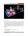
M7C Preamplifier User
Manual
Analog Metric
[M7C PREAMPLIFIER USER MANUAL] Analog Metric
INTRODUCTION
Circuit design is with reference to the classical Marantz 7C. It produces sweet and detail
sound. Capacitors in audio grade are used for high voltage filtering and AC signal
coupling. Low voltage dropout regulator LT1085 is employed in regulating power supply
for tubes filament, which gives a maximum output driving current of the IC is 3A which
is far enough for filament power supply. To enhance the performance of the power
supply unit, the lengths of power routing path and signal paths are minimized so as to
minimize the total path impedances. The placement of the components of the built-in
rectifying and regulating circuits are packaged closely together and are far from the
amplifier core. Also the R14 and R30 are provided for an alternate the biasing at second
amplifying stage.
FEATURES
•
•
•
•
Three vacuum tubes 12AX7
Two single-ended inputs and two single-end outputs for stereo
Voltage gain: 20dB
Dynamic range: output voltage max. 20Vrms
www.analogmetric.com
Page 2
[M7C PREAMPLIFIER USER MANUAL] Analog Metric
•
•
•
•
•
S/N ration: >90dB
Built-in voltage regulation circuit.
Power requirements: one 200V AC(100mA) and one 12.6V AC(1A)
PCB dimension: 110mm (W) x 200mm (L)
PCB thickness: 2.5mm, double layer, 2oz copper.
PRECAUTIONS
•
•
•
•
Do not use finger or any body parts to touch the components or board! It is hazardous,
since the high voltage capacitors may not be fully discharges after switched off the
power supply.
Turn off the power supply if the transformer is getting hot or some smoke is observed
or strange buzz sound is heard.
Fuse should be used either in power transformer or main socket to avoid accidentally
large current drawing.
Always contact technicians or experts to seek help.
PROCEDURES
1. Solder all the components according to the schematic, part list, and photo.
2. Unplug the vacuum tubes. Connect the power supply and measure the voltage at J1
and J2 without applying input signal. The voltage of J1 connecter (marked with 200-0)
should be 200VAC for high voltage supply and J2 connector (marked with 12.6-0)
should be 12.6VAC for filament power supply.
3. If the AC voltages at the J1 and J2 are corrected. Then, measure the voltages at C13
which is near 240V DC and the voltage between PIN 4 and PIN 5 of tube sockets are
12.6V.
4. If everything is ok, you can plug the tubes in the sockets and turn on the power supply.
5. Good luck and enjoy it.
If you have any problem
[email protected]
in
assembly,
please
contact
us
by
email
to
www.analogmetric.com
Page 3