1
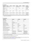
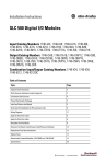
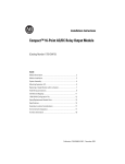
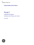
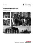
Step 1 - Select:
• I/O modules – available in a
variety of densities and voltage
options. Some modules have
diagnostic features, individually
isolated inputs/outputs or
electronic protection.
• interface modules (IFMs) or
prewired cables (optional)
1746 Digital I/O modules
Select SLC 500 I/O Modules
Digital I/O modules, analog I/O modules, and specialty temperature, counting, process
control, and BASIC language modules are available to help you create a custom solution
for your application.
Digital I/O modules are available with 4, 8, 16, or 32 channels and in a wide variety of
I/O voltages (including AC, DC, and TTL). Combination modules with 2 inputs/2
outputs, 4 inputs/4 outputs, and 6 inputs/6 outputs are also available.
Terminals on the 4, 8, 12, and 16-channel modules have self-lifting pressure plates that
accept two 14 AWG (2 mm2) wires. LED indicators on the front of each module display
the status of each I/O point.
32-channel I/O modules are equipped with a 40-pin, MIL-C-83503 type header and a
removable wiring connector (1746-N3). The connector can be assembled with the wire
type and length of your choice.
Output modules are available with solid-state AC, solid-state DC, and relay contact type
outputs. High current solid-state output modules, catalog numbers 1746-OBP16, 1746OVP16, and 1746-OAP12, have fused commons with a blown fuse LED indication. The
10
Select SLC 500 I/O Modules
1746-OB16E, 1746-OB6EI, and 1746-OB32E modules provide electronic protection
from short circuit and overload conditions.
Wiring of 16 and 32-channel modules can also be accomplished with a bulletin 1492
interface module and pre-wired cable. All 16-channel I/O modules and catalog numbers
1746-OX8, 1746-OBP8, 1746-OAP12, 1746-IO12 are equipped with color-coded
removable terminal blocks.
Digital I/O Module Overview
Catalog Number
Voltage Category
I/O Points
Description
For Detailed Specifications, See
1746-IB8
24V DC
8
Current Sinking DC Input Module
1746-IB16
24V DC
16
Current Sinking DC Input Module
Sinking DC Input Modules
page 11
1746-IB32
24V DC
32
Current Sinking DC Input Module
1746-ITB16
24V DC
16
Fast Response DC Sinking Input Module
1746-IC16
48V DC
16
Current Sinking DC Input Module
1746-IH16
125V DC
16
Current Sinking DC Input Module
1746-IV8
24V DC
8
Current Sourcing DC Input Module
1746-IV16
24V DC
16
Current Sourcing DC Input Module
1746-IV32
24V DC
32
Current Sourcing DC Input Module
1746-ITV16
24V DC
16
Fast Response DC Sourcing Input Module
1746-IG16(1)
5V DC
16
Current Sourcing TTL Input Module
1746-OB6EI
24V DC
6
Electronically Protected Isolated Sourcing DC
Output Module
1746-OB8
24V DC
8
Current Sourcing DC Output Module
1746-OB16
24V DC
16
Current Sourcing DC Output Module
1746-OB16E
24V DC
16
Electronically Protected Current Sourcing DC
Output Module
1746-OB32
24V DC
32
Current Sourcing DC Output Module
1746-OB32E
24V DC
32
Electronically Protected Current Sourcing DC
Output Module
1746-OBP8
24V DC
8
High Current Sourcing DC Output Module
1746-OBP16
24V DC
16
High Current Sourcing DC Output Module
1746-OV8
24V DC
8
Current Sinking DC Output Module
1746-OV16
24V DC
16
Current Sinking DC Output Module
1746-OV32
24V DC
32
Current Sinking DC Output Module
1746-OVP16(2)
24V DC
16
High Current Sinking DC Output Module
1746-OG16(1)
5V DC
16
Current Sinking TTL Output Module
DC Modules
(2)
AC Modules
Publication 1747-SG001E-EN-E - February 2013
Sourcing DC Input Modules
page 12
Sourcing DC Output Modules
page 13
Sinking DC Output Modules
page 12
12
Select SLC 500 I/O Modules
Sinking DC Input Modules
Specifications
1746-IB8
1746-IB16
1746-IB32
Voltage, Off-State Input, max.
5.0V DC
Nominal Input Current
8 mA @ 24V DC
5.1 mA @
24V DC
Current, Off-State Input, Max.
1 mA
1.5 mA
Signal On Delay, Max
8 ms max
3 ms max
Signal Off Delay, Max
8 ms max
3 ms max
1746-IC16
1746-IH16(1)
1746-ITB16
10V DC
20V DC
5V DC
4.1 mA @ 48V DC
2.15 mA @ 125V DC
2.25 mA @ 132V DC
8 mA @ 24V DC
0.8 mA
1.5 mA
4 ms max
9 ms max
0.30 ms max
4 ms max
9 ms max
0.50 ms max
(1) If the input module is connected in parallel with an inductive load, use surge suppression across the load to protect the input module from damage caused by reverse
voltage. Refer to the SLC 500 Modular Hardware Style User Manual, publication 1747-UM011, for more information on surge suppression.
(2) Maixumum Points ON Simultaneously: 16 @ 146V DC and 30 °C (86 °F); 12 @ 146V DC and 50 °C (122 °F); 14 @ 132V DC and 55 °C (131 °F); 16 @ 125V DC and
60 °C (140 °F).
Sourcing DC Input Modules
Specifications
1746-IG16
1746-IV8
1746-IV16
1746-IV32
1746-ITV16
Number of inputs
16
8
16
32
16
Points per common
16
8
16
8
16
Voltage category
5V DC
24V DC
24V DC
24V DC
24V DC
Operating voltage range
4.5…5.5V DC(1)
10…30V DC
15…30V DC@ 50 °C (122 °F)
15…26.4V DC@ 60 °C (140 °F)
10…30V DC
Backplane current (mA) @ 5V
140 mA
50 mA
85 mA
50 mA
85 mA
Backplane current (mA) @ 24V
0 mA
0 mA
0 mA
0 mA
0 mA
Voltage, off-state input, max.
2…5.5V DC
5.0V DC
5.0V DC
5.0V DC
5.0V DC
Nominal input current
3.7 mA @ 5V DC 8 mA @ 24V DC
5.1 mA @ 24V DC
8 mA @ 24V DC
Current, off-state input, max.
4.1 mA
1 mA
1.5 mA
1.5 mA
Signal on delay, max
0.25 ms max
8 ms max
3 ms max
0.30 ms max
Signal off delay, max
0.50 ms max
8 ms max
3 ms max
0.50 ms max(2)
(1) 50 mV peak-to-peak ripple (max.)
(2) Typical signal delay for this module: ON = 0.1 ms, OFF = 0.25 ms @ 24V DC.
Sinking DC Output Modules
Specifications
1746-OG16
1746-OV8
1746-OV16
1746-OV32
1746-OVP16(5)
Number of outputs
16
8
16
32
16
Points per common
16
8
16
16
16
Voltage category
5V DC
24V DC
Operating voltage range
4.5…5.5V DC(2)
10…50V DC
5…50V DC
20.4…26.4V DC
Backplane current (mA)
@ 5V
180 mA
135 mA
270 mA
190 mA
250 mA
Backplane current (mA)
@ 24V
0 mA
0mA
0 mA
0 mA
0 mA
Publication 1747-SG001E-EN-E - February 2013
Select SLC 500 I/O Modules
13
Sinking DC Output Modules
Specifications
1746-OG16
1746-OV8
1746-OV16
1746-OV32
1746-OVP16(5)
Voltage drop, on-state
output, max.
—
1.2V @ 1.0 A
1.2V @ 0.5 A
1.2V @ 0.5 A
1.0 V @ 1.0 A
Load current, min.
0.15 mA
1 mA
1 mA
1 mA
1 mA
Leakage current, off-state
output,max
0.1 mA
1 mA(3)
1 mA(3)
1 mA(3)
1 mA(3)
Signal On Delay, max
(resistive load)
0.25 ms
0.1 ms
0.1 ms
0.1 ms
0.1 ms(6)
Signal Off Delay, max
(resistive load)
0.50 ms
1.0 ms
1.0 ms
1.0 ms
1.0 ms
Continuous current per
module
N/A
8.0 A @ 30 °C (86 °F)
4.0 A @ 60 °C (140 °F)
8.0 A @ 0…60 °C
(32…140 °F)
6.4 A @ 0…60 °C
(32…140 °F)
Continuous current per
point
24 mA
1.0 A @ 30 °C (86 °F)
0.5 A @ 60 °C (140 °F)
0.50 A @ 30 °C
0.25 A @ 60 °C
1.5 A @ 30 °C (86 °F)
1.0 A @ 60 °C (140 °F)(7)
Surge current per point
for 10 ms(1)
N/A
3.0 A
1.0 A @ 30 °C (86 °F)
1.0 A @ 60 °C (140 °F)
4.0 A(8)
0.50 A @30 °C (86 °F)
0.25 A @60 °C (140 °F)(4)
(1) Repeatability is once every 1 s @ 30 °C (86 °F). Repeatability is once every 2 s @ 60 °C (140 °F).
(2) 50 mV peak to peak ripple, max.
(3) To limit the effects of leakage current through solid-state outputs, a loading resistor can be connected in parallel with your load. For transistor outputs, 24V DC operation,
use a 5.6 K Ω, 1/2 W resistor.
(4) Recommended surge suppression: For transistor outputs, when switching 24V DC inductive loads, use a 1N4004 diode reverse-wired across the load. Refer to the SLC 500
Modular Hardware Style User Manual, publication 1747-UM011, for more information on surge suppression.
(5) The 1746-OVP16 module features a fused common and blown fuse LED indicator.
(6) Fast turn-off modules provide fast OFF delay for inductive loads. Fast turn-off delay for inductive loads is accomplished with surge suppressors on this module. A
suppressor at the load is not needed unless another contact is connected in series. If this is the case, a 1N4004 diode should be reverse wired across the load. This defeats
the fast turn-off feature. Comparative OFF delay times for 1746-OB8, 1746-OV8 and fast turn-off modules, when switching Bulletin 100-B110 (24 W sealed) contactor, are:
1746-OB8 and 1746-OV8 modules OFF delay = 152 ms; fast turnoff modules OFF delay = 47 ms.
(7) Fast off-delay for inductive loads is accomplished with surge suppressors on the 1746-IB6EI and 1746-OBP8 series B and later, 1746-OB16E series B and later, 1746-OBP16
and 1746-OVP16 modules. A suppressor at the load is not needed unless another contact is connected in series. If this is the case, a 1N4004 diode should be reverse-wired
across the load. This defeats the fast turn-off feature.
(8) Surge current = 32 A per module for 10 ms.
Sourcing DC Output Modules
Specifications
1746-OB6EI
1746-OB8
1746-OB16
1746-OB16E
1746-OB32
1746-OB32E
Number of outputs 6 Electronically
Protected
8
16
16
Electronically
Protected
32
32
8
Electronically
Protected
16(5)
Points per
common
Individually
isolated
8
16
16
16
16
4
16
Voltage category
24V DC
Operating voltage
range
10 …30V DC
10…50V DC
10…30V DC
5…50V DC
10…30V DC
20.4…26.4V DC
Backplane current
(mA) @ 5V
46 mA
135 mA
280 mA
135 mA
190 mA
Backplane current
(mA) @ 24V
0 mA
0 mA
0 mA
0 mA
0 mA
0 mA
1746-OBP8(4)
1746-OBP16
135 mA
250 mA
0 mA
0 mA
Publication 1747-SG001E-EN-E - February 2013
Select SLC 500 I/O Modules
45
Relay Master and Expander 40-Terminal XIMs
Description
Catalog Number
I/O Module Catalog Number 1746IB32
IV32
OB32
OB32E
OV32
Relay Master
40-pin master with eight (8) 24V DC relays
1492-XIM4024-8R
–
–
H
H
–
40-pin master with sixteen (16) 24V DC relays
1492-XIM4024-16R
–
–
H
H
–
40-pin master with sixteen (16) 24V DC relays with
fusing
1492-XIM4024-16RF
–
–
H
H
–
Expander with eight (8) 24V DC relays
1492-XIM24-8R
–
–
(1)
(1)
–
Expander with eight (8) 120V AC relays
1492-XIM120-8R
–
–
–
–
–
–
–
(2)
(2)
–
Relay Expander
Expander with sixteen (16) 24V DC relays with fusing 1492-XIM24-16RF
Fusible Expander
8-channel expander with 24V DC blown fuse
indicators
1492-XIMF-F24-2
–
–
(1)
(1)
–
8-channel expander with 120V AC blown fuse
indicators
1492-XIMF-F120-2
–
–
–
–
–
1492-XIMF-2
–
–
(1)
(1)
–
Feed-through Expander
Expander with eight (8) feed-through channels 132V
AC/DC max
(1) Two or three expanders can be connected to a master to provide a total of 32 outputs. An extender cable is included with each expander to connect it to the master.
(2) Can have one expandable module per master.
Pre-Wired Cables for 1746 Digital I/O Modules
These pre-wired cables have a pre-wired removable terminal block (RTB) on one end to
connect to the front of a Bulletin 1746 digital I/O module and a connector on the other
end to plug into a 20- or 40-terminal IFM/XIM. You must first select the IFM/XIM
from one of the preceding selection tables.
Cable Catalog Number
Standard Cable Lengths
Build to Order
Available
Number of
Conductors
Mating I/O Module Catalog Number
1492-CABLE(1)A
0.5, 1.0, 2.5, 5.0 m
Yes
20
1746-IA16, -IM16
1492-CABLE(1)B
0.5, 1.0, 2.5, 5.0 m
Yes
20
1746-IB16, -IH16, -IN16, -ITB16, -ITV16
1492-CABLE(1)C
0.5, 1.0, 2.5, 5.0 m
Yes
20
1746-OA16
1492-CABLE(1)CR
0.5, 1.0, 2.5, 5.0 m
Yes
20
1746-OA16
1492-CABLE(1)D
0.5, 1.0, 2.5, 5.0 m
Yes
20
1746-OW16, -OX8
1492-CABLE(1)E
0.5, 1.0, 2.5, 5.0 m
Yes
20
1746-IG16, -OB16, -OB16E, -OBP16,
-OG16, -OV16, -OVP16
Publication 1747-SG001E-EN-E - February 2013
46
Select SLC 500 I/O Modules
Cable Catalog Number
Standard Cable Lengths
Build to Order
Available
Number of
Conductors
Mating I/O Module Catalog Number
1492-CABLE(1)G
0.5, 1.0, 2.5, 5.0 m
Yes
20
1746-OA16
1492-CABLE(1)H
0.5, 1.0, 2.5, 5.0 m
Yes
20
1746-IB32, -IV32, -OB32, -OB32E, -OV32
1492-CABLE(1)N
0.5, 1.0, 2.5, 5.0 m
Yes
20
1746-OW16, -OX8
1492-CABLE(1)S
0.5, 1.0, 2.5, 5.0 m
Yes
20
1746-OX8
(1) Cables are available in standard lengths of 0.5 m, 1.0 m, 2.5 m, and 5.0 m. To order, insert the code for the desired cable length into the cat. no. (005 = 0.5 m, 010 = 1.0 m,
025 = 2.5 m, and 050 = 5.0 m). Example: Cat. No. 1492-CABLE005N is for a 0.5 m cable that could be used to connect a catalog number 1492-IFM20D24N IFM to a Catalog
Number 1746-OW16 I/O module. Build-to-order lengths are also available.
I/O Module-Ready Cables for 1746 Digital I/O Modules
The I/O module-ready cables have a pre-wired RTB on one end to plug onto the front of
a Bulletin 1746 I/O module and 20 or 40 individually colored #18 AWG conductors on
the other end. These cables provide the convenience of pre-wired connections at the I/O
module end, while still allowing the flexibility to fieldwire to standard terminal blocks of
your choice.
I/O Module-Ready Cables for 1746 Digital I/O Modules
Cable Catalog Number
Standard Cable
Lengths
Build to Order
Available
Number of
Conductors
Mating I/O Module Catalog Number
1492-CABLE(1)N3
1.0, 2.5, 5.0 m
Yes
40
1746-IB32, -IV32, -OB32, -OV32, -OB32E
1492-CABLE(1)RTBB
1.0, 2.5, 5.0 m
Yes
20
1746-IB16, -IC16, -IG16, -IH16, -IN16, -ITB16, -ITV16, -IV16,
-OB16, -OB16E, -OBP8, -OBP16, -OG16, -OV16, -OVP16
1492-CABLE(1)RTBO
1.0, 2.5, 5.0 m
Yes
20
1746-OW16, -OX8
1492-CABLE(1)RTBR
1.0, 2.5, 5.0 m
Yes
20
1746-IA16, -OA16, -OAP12, -IM16
(1) Cables are available in standard lengths of 0.5 m, 1.0 m, 2.5 m, and 5.0 m. To order, insert the code for the desired cable length into the cat. no. (005 = 0.5 m, 010 = 1.0 m,
025 = 2.5 m, and 050 = 5.0 m). Example: Cat. No. 1492-CABLE005N is for a 0.5 m cable that could be used to connect a catalog number 1492-IFM20D24N IFM to a Catalog
Number 1746-OW16 I/O module. Build-to-order lengths are also available.
IMPORTANT
Publication 1747-SG001E-EN-E - February 2013
The following I/O Modules do not have RTBs: 1746-IA4, 1746-IA8,
1746-IB8, 1746-IM4, 1746-IM8, 1746-IV8, 1746-OA8, 1746-OB8.