1
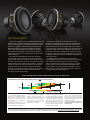
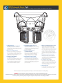
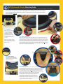
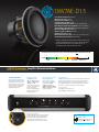
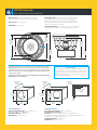
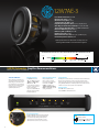
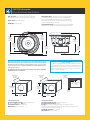
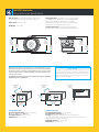
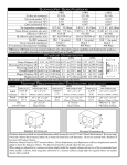
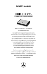
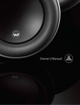
W7AE Owner’s Manual An Introduction Thank you for purchasing a JL Audio W7AE subwoofer driver. The W7AE embodies JL Audio’s commitment to pushing the envelope of speaker technology, with eight patented technologies, a design patent and a completely unique set of component parts. Each W7AE model has been meticulously engineered to reproduce sub-bass with extreme fidelity at any volume level, provided it is installed and tuned properly. Please review the information in this document carefully so as to maximize your enjoyment of the W7AE’s capabilities. Two enclosure recommendations are listed for each model, one sealed and one ported. In most cases, the sealed enclosure design will give you the best overall sound quality and take up the least space in your vehicle. The ported enclosure design will deliver additional output over the sealed enclosure (about 3 - 4 dB more) and will also maintain excellent sound quality, but it will require significantly more space to install. The recommended ported enclosure is not designed for peaky “competition SPL” performance, but rather for music listening. It will be very loud and sound extremely good when set up properly. In addition to the enclosure recommendations, we also provide recommended amplifier settings for JL Audio amplifiers commonly used with W7AE’s. Some of this information is also applicable with other brands of amplifiers (like crossover points and slopes), some is not (like the voltage levels specified for input sensitivity settings). Please note that W7AE’s rarely require any equalization to produce smooth frequency response. If you have an equalizer in your system (or one is included in your head unit or amplifier), defeat all bands below 125 Hz before dialing in your new system settings. For optimum sub-bass performance, the amplifier input sensitivity must be adjusted to avoid excessive distortion (clipping) of the amplifier output. Overly high input sensitivity settings result in no additional clean output but will result in poor sound quality and reduced speaker reliability. With W7AE subwoofers, a clipped amplifier output may manifest itself audibly as a lowlevel “mechanical” sound coming from the speakers. Proper input sensitivity setting will avoid this problem. Please consult the input sensitivity setting information on page 14 of this book. RECOMMENDED CONTINUOUS (RMS) POWER RANGE FOR ONE SUBWOOFER DRIVER: 125W 250W 500W 1000W 2000W 4000W 13W7AE 12W7AE 10W7AE 8W7AE GREEN (MINIMUM): From a reliability standpoint, this zone represents a very comfortable operating power range for each driver. This level of power will not stress the woofer but will not extract all of its performance potential, either. Use of less than the minimum power level will not damage the woofer, but may result in unsatisfactory performance. YELLOW (OPTIMUM): This zone represents the best balance between long-term reliability, high output and low distortion performance. In this zone, you will be taking full advantage of the woofer's optimum, low-distortion performance range without undue risk of failure. RED (MAXIMUM): In this zone, low-distortion output and long-term reliability will be compromised (especially by an aggressive user). Slightly more SPL will be gained by pushing the power into this zone, but typically not more than 2dB, compared to the yellow zone. The closer you are to the black zone, the higher the likelihood of driver failure. Operate with caution. BLACK (WARRANTY VOID): We do not recommend operating woofers at this level of power. In this zone, there is a very high probability that the driver will fail due to excessive heat and/or mechanical stress. Subwoofer drivers operated at these levels of power are NOT covered under warranty. When designing systems with W7AE drivers, it is very important to achieve a good power match between the subwoofer amplifier and the subwoofer driver's capabilities. The power levels listed in the above chart represent continuous (RMS) amplifier power per woofer and assume that the user will regularly make full use of that power without drastically overdriving (clipping) the amplifier(s). Make sure you factor system impedance and the total number of subwoofers into your calculations. Adhering to these power recommendations will result in systems that are both reliable and enjoyable. 2 W7AE Subwoofer Drivers: Tight. The ultimate no-compromise subwoofer for those seeking extreme output and sublime sound quality. 1-O verRoll™ Surround (U.S. Patent #5,687,247 and #5,949,898) By utilizing space wasted in conventional speakers, this ground-breaking innovation controls the W7AE’s massive excursion without sacrificing precious cone area. 4 - Plateau-Reinforced Spider Attachment (U.S. Patent #6,118,884) A derivative of JL Audio’s famous VRC technology, this bulletproof suspension attachment relieves stress from the spider material at high-excursions for enhanced reliability. 2 - W-Cone™ (U.S. Patent #6,496,590) The W-Cone™ is a unit-body cone assembly that delivers astonishing cone stiffness with minimal mass. The shape also provides incredible torsional rigidity, which is critical to maintaining voice coil alignment at the suspension limits. 5 - Radially Cross-Drilled Pole Piece (U.S. Patent #6,243,479) This innovative venting system greatly enhances thermal dissipation and power handling by directing air flow onto the voice coil former, working in conjunction with technology #6. 3 - Floating-Cone™ Attach Method (U.S. Patent #6,501,844) Our newly conceived assembly technique ensures proper surround geometry in the assembled speaker for better excursion control and dynamic voice coil alignment. A small detail that means a lot when you’re pumping the cone to the excursion extremes the W7AE is capable of. 6 - Elevated Frame Cooling (U.S. Patent #D472,891, #6,219,431 and #6,229,902) The elevated frame design of the W7AE delivers cool air through slots directly above the top-plate to the voice coil of the speaker. This not only enhances power handling, but also sound quality by minimizing dynamic parameter shifts and power compression. 7-H ighly Linear, DMA-Optimized Motor System DMA is JL Audio’s proprietary Dynamic Motor Analysis system and is aimed at improving dynamic motor behavior. As a result of DMA optimization, W7AE motors remain linear in motor force over an extreme range of excursion and also maintain a highly stable fixed magnetic field in the gap over a wide power range. This leads to vastly reduced distortion and faithfully reproduced transients... or put simply: tight, clean, articulate bass. 8-H uge Diameter, Progressive-Roll Spider Arrived at after intense computer analysis and optimization, the W7AE spiders provide precise control and motor/voice coil alignment without prematurely limiting excursion. 9 - Co-Extruded Double Lead-Wires The extruded casing and carefully engineered attachments ensure controlled lead-wire behavior under the most extreme excursion demands. Two conductors are used per connection for ample current carrying capability. 10 - U ltra-long Voice Coil To allow extreme linear excursion, phenomenal power handling and control, control, control. In addition to the patented technologies listed above, multiple U.S. and International patents are currently pending. WARNING: Prolonged exposure to high sound pressure levels can lead to permanent hearing loss. W7AE subwoofers are capable of reproducing sound at extremely high sound pressure levels. Please exercise restraint in the operation of your system in order to preserve your hearing and your long-term enjoyment of this product’s sound quality capabilities. 3 W7AE Subwoofer Drivers: Mounting Guide. The ultimate no-compromise subwoofer for those seeking extreme output and sublime sound quality. Please review the mounting procedures thoroughly before attempting to remove the speaker from its shipping baffle. The W7AE mounts like no other speaker and care must be taken to follow these instructions precisely. 2e 2c 1 2a Step 1: Your Tools When you remove the W7AE from its shipping carton, it is attached to an MDF baffle board. Make sure you keep this baffle board and all the packing material in the unlikely event that the W7AE ever needs to be shipped back to JL Audio for service. 2b 2f 2d Correct Wrong Step 2: Remove Clamp-Ring Gently insert the tip of the large flat-head screwdriver between the shiny aluminum clamp-ring and the foam surround (picture 2a). Be careful not to push the screwdriver too far down or it will wedge behind the hidden O-Ring (picture 2b). Gently twist the screwdriver to “pop” the clamp-ring off of the O-Ring and frame (picture 2c). This should require little effort... if you are encountering high resistance, pull the screwdriver up a bit to make sure it is not wedged behind the O-Ring. Once you have released the tip of the clamp-ring, a gentle push with your thumb in the direction of the speaker circumference (picture 2d) will separate the clamp-ring fully (picture 2f). Do not pull up on the ring until it is completely removed (picture 2g). Two tools are required to install a W7AE: a large flat blade screwdriver and an electric screwdriver with a #2 Phillips-head bit. Wrong 2g Correct 4c Wrong 4b 3a Step 3: Remove O-Ring 4d Once the clamp-ring is removed, the steel O-Ring is exposed. Gently lift this O-Ring up and off the speaker with your fingertips and set it aside. Wrong 4a 4e Step 4: Remove Screws 3b 4 Once the O-Ring is out of the way, the surround is completely free of the speaker frame (no glue is used to secure it). Lift the surround up and fold it back inside the speaker frame (picture 4a). This exposes the mounting screws (picture 4b). The surround should be folded back and in towards the center of the speaker (picture 4c). Do not pull it up (picture 4d) or invert it (picture 4e). While holding the surround back with two fingers as shown, back the first screw out using your electric screwdriver (picture 4f, 4g). Repeat this process eleven more times (there are twelve screws on a W7AE) until you have separated the speaker from the shipping baffle-board. Before you panic, be aware that the surround and cone materials are rugged and will not be damaged if you follow the procedures shown. Only careless acts like picking the speaker up by the surround or creasing it by force will cause permanent damage. 4f 4g Step 5: Ready to Install You are now ready to install the W7AE into its enclosure. The parts are shown below. Step 6: Connect the speaker wires and place the W7AE into the enclosure Connect the positive wire to the red terminal and the negative wire to the black terminal of the W7AE (picture 6a). The 13W7AE (not shown) has dual voice coils and must be wired with its coils in series or in parallel. Once the speaker is wired, gently lower it into the enclosure (picture 6b). This is difficult on a vertical mounting surface (because of the speaker’s weight) so you should enlist the help of a second person. If you need a better grip (or are afraid of smashing your fingers) you can grasp the inside of the speaker’s mounting flange (remember, the surround moves out of the way). This tip is particularly useful with the 13W7AE. 6a 6b 5 Step 7: Screw it in (12 times) Line up the screw holes of the frame with the holes that you have predrilled in your enclosure (you did pre-drill the holes, right?). The W7AE should be attached with heavy screws such as the ones supplied with the speaker. This will necessitate pre-drilling. The use of inferior hardware (i.e. drywall screws) may lead to disastrous consequences, so don’t do it. While holding the surround back with two fingers (picture 7a), screw the speaker into the enclosure (picture 7b). Once all twelve screws are in place (you did use all twelve, right?), place the surround back over the outside of the speaker frame (picture 7c). 7a 7b 8a Step 8: Attach O-Ring Next, take the steel O-Ring that you removed in step 3, and place it over the outside of the surround. Push it down evenly (do not seat one side first) to make sure it seats the lower lip of the surround down to the frame (pictures 8a, 8b). 7c 9e 9a 8b Be sure that the beveled edge of the clamp-ring is “pointing” towards the front of the speaker. The clamp-ring is only designed to work in this orientation. “click” 9b 9d Step 9: Attach Clamp-Ring Place the seam of the clamp-ring where it will be least visible in the installation (usually at the bottom of the speaker). Start one end of the clamp-ring by pressing it in firmly (pictures 9a, 9b). Then work your way around from that point around the speaker, pushing the clamp-ring inward and in the direction of the circumference of the frame (pictures 9c, 9d). If you have achieved a tight fit all around, the seam will be small when you reach the starting point again (pictures 9e, 9f). Check the entire circumference for a tight fit just to be sure. 9f 9c That’s it! You’ve just installed a W7AE! 5 13W7AE-D1.5 Free Air Resonance (Fs): 23.5 Hz Electrical “Q” (Qes): 0.476 Mechanical “Q” (Qms): 7.517 Total Speaker “Q” (Qts): 0.448 Equivalent Compliance (Vas):3.68 cu. ft. (104.3 ltrs) One-Way, Linear Excursion (Xmax)*: 1.25 in. (32 mm) Thermal Power Handling (Pt):1500 Watts Continuous Reference Efficiency (no): 0.269 % Efficiency (SPL @ 1W/1m): 86.3 dB DC Resistance (Re): 2.41Ω Effective Piston Area (Sd):107.35 sq. in. (0.0693 sq. m) Nominal Impedance (Znom): Dual 1.5Ω * Xmax specifications are derived via one-way voice coil overhang method with no correction factors applied. **F or parallel-wired voice coils, divide “Re” by 4. All other specifications remain the same. RECOMMENDED CONTINUOUS (RMS) POWER RANGE FOR ONE SUBWOOFER DRIVER: 500W 750W 1000W 1500W 2000W 13W7AE 13W7AE Subwoofer: Amplifier Recommendation. HD1200/1 (shown) or 1200/1v3 JL Audio HD1200/1: These settings are intended as a “baseline” for tuning your system. Depending on your vehicle and your preferences, some variation in the crossover and bass control settings may be necessary for optimum performance. Filter Mode & Slope: Set “Mode” switch to “LP”. Set “Slope” switch to “24dB”. Set “Filter Freq. (Hz)” knob to “85”. Lower settings are likely to result in a p oor transition between the upper response of the W7AE and the lower response of the mid-bass speakers. Input Sensitivity Controls: Proper adjustment of these controls is critical! For virtually all aftermarket head units, set “Input Voltage” to “Low”. See “Input Sensitivity Setting Guide” on pg. 14 for precise setting instructions. Remote Level Control Requires HD-RLC controller (sold separately). Multiple amplifiers can be controlled with one controller by adding standard phone cable splitter (not included). This is a true subwoofer level control, not a “bass boost”. 6 Output Polarity: Carefully listen to the sub-bass to mid-bass transition with music that h as strong mid-bass content. Select the switch position which gives the smoothest, most natural mid-bass response. If using multiple HD1200/1’s on multiple subwoofers, make sure this switch is set to the same position o n all amplifiers. Infrasonic Filter: Turn “Off” for Sealed Enclosure. Select “30Hz” for Ported Enclosure. = position of knob = position of switch = switch with two possible positions = setting will vary (see sidebar) 4000 13W7AE Subwoofer: Driver & Enclosure Specifications Grille Clearance: 2.7 in. (69 mm) from the bottom of the mounting flange to the lowest inside surface of the grille. Displacement: 0.21 cu. ft. (5.9 ltrs) Net Weight: 52 lbs. (23.6 kg) Mounting Hardware: Twelve #12 x 1.75" long clear, zinc-plated steel Phillips pan-head sheet metal screws (included) or twelve #12-28 long steel Phillips pan-head machine screws with #12-28 T-Nuts, each at least 1/2-inch (12.5 mm) longer than the thickness of the mounting baffle (not included). Unpacking/Mounting: Please refer to the “How to: Mount a W7AE Subwoofer ” on pages 4 & 5 for detailed, step-by-step instructions. Bolt Hole Circle 12.7 in. (323 mm) 12 Holes Mounting Hole Diameter 11.9 in. (302 mm) Magnet Diameter 8.38 in. (213 mm) Mounting Depth 10.5 in. (267 mm) Overall Diameter 14 in. (356 mm) Net volumes given below do not include the air volume displaced by the speaker (Driver Displacement). This value must be added to the net volume along with the displacement of any braces and/or ports (if applicable) to arrive at a gross internal volume. Air inside a port is not part of the effective net volume. Calculate ports as solid, not hollow objects. SAFETY NOTICE! It is absolutely essential that the completed subwoofer enclosure is mounted firmly to the vehicle with heavy steel bolts (1/2 inch diameter) and large steel washers on both sides of the bolts. This will reduce the likelihood of occupant injury in the event of a collision or sudden deceleration. The dimensions given for the enclosure examples below take all applicable displacements into consideration. External Depth 18.875 in. (479 mm) Overall Depth 12 in. (305 mm) Slot Port Depth 26.25 in. (667mm) External Depth 17.25 in. (438 mm) Slot Width 2.25 in. (57 mm) Extension Length 7.875 in. (200 mm) External Height 16.0 in. (406 mm) External Height 16.0 in. (406 mm) Slot Height 14.5 in. (368 mm) Slot Width 2.25 in. (57 mm) External Width 16.0 in. (406mm) SEALED ENCLOSURE: Recommended Net Volume: 1.875 cu. ft. (53.1 ltrs.) Fc: 40.5 Hz F3: 37.4 Hz Qtc: 0.771 Front Baffle Thickness: 1 in. (25 mm) Wall Thickness: 0.75 in. (19 mm) External Width 25.875 in. (657 mm) PORTED ENCLOSURE: Recommended Net Volume: 2.375 cu. ft. (67.3 ltrs.) Recommended Port Tuning: 34.6 Hz Port Type: “Slot” ports are recommended. See information above. The port recommendations listed above are derived through actual tests and measurements (not computer simulations). Front Baffle Thickness: 1 in. (25 mm) Wall Thickness: 0.75 in. (19 mm) 7 12W7AE-3 Free Air Resonance (Fs): 27.2 Hz Electrical “Q” (Qes): 0.514 Mechanical “Q” (Qms): 7.807 Total Speaker “Q” (Qts): 0.482 Equivalent Compliance (Vas):2.33 cu. ft. (66.0 ltrs) One-Way, Linear Excursion (Xmax)*: 1.15 in. (29 mm) Thermal Power Handling (Pt):1000 Watts Continuous Reference Efficiency (no): 0.249 % Efficiency (SPL @ 1W/1m): 86.2 dB DC Resistance (Re): 2.47Ω Effective Piston Area (Sd):84 sq. in. (0.0542 sq. m) Nominal Impedance (Znom): 3Ω *X max specifications are derived via one-way voice coil overhang method with no correction factors applied. RECOMMENDED CONTINUOUS (RMS) POWER RANGE FOR ONE SUBWOOFER DRIVER: 250W 500W 750W 1000W 2000W 12W7AE 12W7AE Subwoofer: Amplifier Recommendations. HD750/1 (shown) or JX1000/1D JL Audio HD750/1: These settings are intended as a “baseline” for tuning your system. Depending on your vehicle and your preferences, some variation in the crossover and bass control settings may be necessary for optimum performance. Filter Mode & Slope: Set “Mode” switch to “LP”. Set “Slope” switch to “24dB”. Set “Filter Freq. (Hz)” knob to “85”. Lower settings are likely to result in a p oor transition between the upper response of the W7AE and the lower response of the mid-bass speakers. Input Sensitivity Controls: Proper adjustment of these controls is critical! For virtually all aftermarket head units, set “Input Voltage” to “Low”. See “Input Sensitivity Setting Guide” on pg. 14 for precise setting instructions. Remote Level Control Requires HD-RLC controller (sold separately). Multiple amplifiers can be controlled with one controller by adding standard phone cable splitter (not included). This is a true subwoofer level control, not a “bass boost”. 8 Output Polarity: Carefully listen to the sub-bass to mid-bass transition with music that h as strong mid-bass content. Select the switch position which gives the smoothest, most natural mid-bass response. If using multiple HD750/1’s o n multiple subwoofers, make sure this switch is set to the same position o n all amplifiers. Infrasonic Filter: Turn “Off” for Sealed Enclosure. Select “30Hz” for Ported Enclosure. = position of knob = position of switch = switch with two possible positions = setting will vary (see sidebar) 4000 12W7AE Subwoofer: Driver & Enclosure Specifications Grille Clearance: 2.6 in. (66 mm) from the bottom of the mounting flange to the lowest inside surface of the grille. Mounting Hardware: Twelve #10 x 1.75” long clear, zinc-plated steel Phillips pan-head sheet metal screws (included) or twelve #10-32 long steel Phillips pan-head machine screws with #10-32 T-Nuts, each at least 1/2-inch (12.5 mm) longer than the thickness of the mounting baffle (not included). Displacement: 0.14 cu. ft. (4.0 ltrs) Net Weight: 45 lbs. (20.4 kg) Unpacking/Mounting: Please refer to the “How to: Mount a W7AE Subwoofer ” on pages 4 & 5 for detailed, step-by-step instructions. Bolt Hole Circle 11.27 in. (286 mm) 12 Holes Mounting Hole Diameter 10.5 in. (267 mm) Magnet Diameter 7.5 in. (191 mm) Mounting Depth 9.5 in. (241 mm) Overall Diameter 12.5 in. (318 mm) Net volumes given below do not include the air volume displaced by the speaker (Driver Displacement). This value must be added to the net volume along with the displacement of any braces and/or ports (if applicable) to arrive at a gross internal volume. Air inside a port is not part of the effective net volume. Calculate ports as solid, not hollow objects. The dimensions given for the enclosure examples below take all applicable displacements into consideration. External Depth 16.125 in. (410 mm) Overall Depth 11.25 in. (286 mm) SAFETY NOTICE! It is absolutely essential that the completed subwoofer enclosure is mounted firmly to the vehicle with heavy steel bolts (1/2 inch diameter) and large steel washers on both sides of the bolts. This will reduce the likelihood of occupant injury in the event of a collision or sudden deceleration. Slot Port Depth 24.75 in. (629 mm) External Depth 15.875 in. (403 mm) Slot Width 1.875 in. (48 mm) Extension Length 7.9375 in. (202 mm) External Height 15.0 in. (381 mm) External Height 15.0 in. (381 mm) Slot Height 13.5 in. (343 mm) Slot Width 1.875 in. (48 mm) External Width 15.0 in. (381 mm) SEALED ENCLOSURE: Recommended Net Volume: 1.375 cu. ft. (38.94 ltrs.) Fc: 44.7 Hz F3: 40.4 Hz Qtc: 0.791 Front Baffle Thickness: 1 in. (25 mm) Wall Thickness: 0.75 in. (19 mm) External Width 22.75 in. (578 mm) PORTED ENCLOSURE: Recommended Net Volume: 1.75 cu. ft. (51.54 ltrs.) Recommended Port Tuning: 36.7 Hz Port Type: “Slot” ports are recommended. See information above. The port recommendations listed above are derived through actual tests and measurements (not computer simulations). Front Baffle Thickness: 1 in. (25 mm) Wall Thickness: 0.75 in. (19 mm) 9 10W7AE-3 Free Air Resonance (Fs): 30.6 Hz Electrical “Q” (Qes): 0.578 Mechanical “Q” (Qms): 7.647 Total Speaker “Q” (Qts): 0.537 Equivalent Compliance (Vas):1.28 cu. ft. (36.1 ltrs) One-Way, Linear Excursion (Xmax)*: 0.9 in. (23 mm) Thermal Power Handling (Pt):750 Watts Continuous Reference Efficiency (no): 0.171 % Efficiency (SPL @ 1W/1m): 84.3 dB DC Resistance (Re): 2.75Ω Effective Piston Area (Sd):59.8 sq. in. (0.0386 sq. m) Nominal Impedance (Znom): 3Ω * Xmax specifications are derived via one-way voice coil overhang method with no correction factors applied. RECOMMENDED CONTINUOUS (RMS) POWER RANGE FOR ONE SUBWOOFER DRIVER: 250W 500W 750W 1000W 2000W 10W7AE 10W7AE Subwoofer: Amplifier Recommendations. XD600/1v2 (shown) or 600/1v3 JL Audio XD600/1v2: These settings are intended as a “baseline” for tuning your system. Depending on your vehicle and your preferences, some variation in the crossover and bass control settings may be necessary for optimum performance. Filter Mode & Slope: Set “LP Filter Mode/ Slope” switch to “24dB”. Set “Filter Freq. (Hz)” knob to “85”. Lower settings are likely to result in a p oor transition between the upper response of the W7AE and the lower response of the mid-bass speakers. Input Sensitivity Controls: Proper adjustment of these controls is critical! For virtually all aftermarket head units, set “Input Voltage” to “Low”. See “Input Sensitivity Setting Guide” on pg. 14 for precise setting instructions. Remote Level Control Requires HD-RLC controller (sold separately). Multiple amplifiers can be controlled with one controller by adding standard phone cable splitter (not included). This is a true subwoofer level control, not a “bass boost”. Turn-On Mode: All XDv2 models offer the convenience of automatic turn-on (signal or DC-offset sensing), and a dualrange input section that can accept a wide range of input signals, from line-level to high-power, speaker level signals. = position of knob = position of switch = switch with multiple possible positions = setting will vary (see sidebar) 10 4000 10W7AE Subwoofer: Driver & Enclosure Specifications Grille Clearance: 2.25 in. (57 mm) from the bottom of the mounting flange to the lowest inside surface of the grille. Mounting Hardware: Twelve #10 x 1.75” long clear, zinc-plated steel Phillips pan-head sheet metal screws (included) or twelve #10-32 long steel Phillips pan-head machine screws with #10-32 T-Nuts, each at least 1/2-inch (12.5 mm) longer than the thickness of the mounting baffle (not included). Displacement: 0.09 cu. ft. (2.5 ltrs) Net Weight: 30 lbs. (13.6 kg) Mounting Hole Diameter 8.74 in. (222 mm) Unpacking/Mounting: Please refer to the “How to: Mount a W7AE Subwoofer ” on pages 4 & 5 for detailed, step-by-step instructions. Bolt Hole Circle 9.34 in. (237 mm) 12 Holes Magnet Diameter 6.55 in. (166 mm) Mounting Depth 8 in. (203 mm) Overall Depth 9.63 in. (245 mm) Overall Diameter 10.5 in. (267 mm) Net volumes given below do not include the air volume displaced by the speaker (Driver Displacement). This value must be added to the net volume along with the displacement of any braces and/or ports (if applicable) to arrive at a gross internal volume. Air inside a port is not part of the effective net volume. Calculate ports as solid, not hollow objects. The dimensions given for the enclosure examples below take all applicable displacements into consideration. External Depth 15.375 in. (391 mm) SAFETY NOTICE! It is absolutely essential that the completed subwoofer enclosure is mounted firmly to the vehicle with heavy steel bolts (1/2 inch diameter) and large steel washers on both sides of the bolts. This will reduce the likelihood of occupant injury in the event of a collision or sudden deceleration. Slot Port Depth 24.375 in. (619 mm) External Depth 14.625 in. (371 mm) Slot Width 1.5 in. (38 mm) External Height 14.5 in. (368 mm) External Height 14.5 in. (368 mm) External Width 14.5 in. (368 mm) SEALED ENCLOSURE: Recommended Net Volume: 1.25 cu. ft. (35.4 ltrs.) Fc: 43.5 Hz F3: 40.5 Hz Qtc: 0.764 Front Baffle Thickness: 1 in. (25 mm) Wall Thickness: 0.75 in. (19 mm) Extension Length 9.0 in. (229 mm) Slot Height 13.0 in. (330 mm) External Width 21.75 in. (552 mm) Slot Width 1.5 in. (38 mm) PORTED ENCLOSURE: Recommended Net Volume: 1.5 cu. ft. (42.5 ltrs.) Recommended Port Tuning: 35.3 Hz Port Type: “Slot” ports are recommended. See information above. The port recommendations listed above are derived through actual tests and measurements (not computer simulations). Front Baffle Thickness: 1 in. (25 mm) Wall Thickness: 0.75 in. (19 mm) 11 8W7AE-3 Free Air Resonance (Fs): 35.2 Hz Electrical “Q” (Qes): 0.654 Mechanical “Q” (Qms): 9.50 Total Speaker “Q” (Qts): 0.612 Equivalent Compliance (Vas):0.61 cu. ft. (17.4 ltrs) One-Way, Linear Excursion (Xmax)*: 0.75 in. (19 mm) Thermal Power Handling (Pt):500 Watts Continuous Reference Efficiency (no): 0.112 % Efficiency (SPL @ 1W/1m): 82.7 dB DC Resistance (Re): 2.78Ω Effective Piston Area (Sd):38.0 sq. in. (0.0245 sq. m) Nominal Impedance (Znom): 3Ω * Xmax specifications are derived via one-way voice coil overhang method with no correction factors applied. RECOMMENDED CONTINUOUS (RMS) POWER RANGE FOR ONE SUBWOOFER DRIVER: 125W 250W 500W 1000W 2000W 8W7AE 8W7AE Subwoofer: Amplifier Recommendations. XD600/1v2 (shown) or JX500/1 JL Audio XD600/1v2: These settings are intended as a “baseline” for tuning your system. Depending on your vehicle and your preferences, some variation in the crossover and bass control settings may be necessary for optimum performance. Filter Mode & Slope: Set “LP Filter Mode/ Slope” switch to “24dB”. Set “Filter Freq. (Hz)” knob to “85”. Lower settings are likely to result in a p oor transition between the upper response of the W7AE and the lower response of the mid-bass speakers. Input Sensitivity Controls: Proper adjustment of these controls is critical! For virtually all aftermarket head units, set “Input Voltage” to “Low”. See “Input Sensitivity Setting Guide” on pg. 14 for precise setting instructions. Remote Level Control Requires HD-RLC controller (sold separately). Multiple amplifiers can be controlled with one controller by adding standard phone cable splitter (not included). This is a true subwoofer level control, not a “bass boost”. Turn-On Mode: All XDv2 models offer the convenience of automatic turn-on (signal or DC-offset sensing), and a dualrange input section that can accept a wide range of input signals, from line-level to high-power, speaker level signals. = position of knob = position of switch = switch with multiple possible positions = setting will vary (see sidebar) 12 4000W 8W7AE Subwoofer: Driver & Enclosure Specifications Grille Clearance: 2.3125 in. (25 mm) from the bottom of the mounting flange to the lowest inside surface of the grille. Mounting Hardware: Twelve #8 x 1.00” long clear, zinc-plated steel Phillips pan-head sheet metal screws (included) or twelve #8-32 long steel Phillips pan-head machine screws with #8-32 T-Nuts, each at least 1/2-inch (12.5 mm) longer than the thickness of the mounting baffle (not included). Displacement: 0.06 cu. ft. (1.7 ltrs) Net Weight: 17 lbs. (7.8 kg) Mounting Hole Diameter 6.94 in. (176 mm) Magnet Diameter 5.79 in. (147 mm) Unpacking/Mounting: Please refer to the “W7 Installation: Mounting System ” sheet for detailed, step-by-step instructions. Bolt Hole Circle 7.39 in. (188 mm) 12 Holes Overall Diameter 8.5 in. (216 mm) Net volumes given below do not include the air volume displaced by the speaker (Driver Displacement). This value must be added to the net volume along with the displacement of any braces and/or ports (if applicable) to arrive at a gross internal volume. Air inside a port is not part of the effective net volume. Calculate ports as solid, not hollow objects. The dimensions given for the enclosure examples below take all applicable displacements into consideration. External Depth 14.0 in. (356 mm) Mounting Depth 6.83 in. (173 mm) SAFETY NOTICE! It is absolutely essential that the completed subwoofer enclosure is mounted firmly to the vehicle with heavy steel bolts (1/2 inch diameter) and large steel washers on both sides of the bolts. This will reduce the likelihood of occupant injury in the event of a collision or sudden deceleration. Slot Port Depth 27.875 in. (708 mm) External Depth 14.0 in. (356 mm) Extension Length 13.1875 in. (335 mm) External Height 12.875 in. (327 mm) External Height 12.875 in. (327 mm) External Width 12.875 in. (327 mm) SEALED ENCLOSURE: Recommended Net Volume: 0.875 cu. ft. (24.8 ltrs.) Fc: 45.9 Hz F3: 41.3 Hz Qtc: 0.798 Front Baffle Thickness: 0.75 in. (19 mm) Wall Thickness: 0.75 in. (19 mm) Overall Depth 8.32 in. (211 mm) Slot Width 1.375 in. (35 mm) Slot Height 11.375 in. (289 mm) External Width 18.75 in. (476 mm) Slot Width 1.375 in. (35 mm) PORTED ENCLOSURE: Recommended Net Volume: 1.0 cu. ft. (28.3 ltrs.) Recommended Port Tuning: 36.8 Hz Port Type: “Slot” ports are recommended. See information above. The port recommendations listed above are derived through actual tests and measurements (not computer simulations). Front Baffle Thickness: 0.75 in. (19 mm) Wall Thickness: 0.75 in. (19 mm) 13 Input Sensitivity “Gain” Setting Guide for JL Audio Subwoofer Amplifiers Following the directions below will allow you to easily adjust the input sensitivity of the amplifier(s), using commonly available equipment. Properly setting levels according to this procedure will result in optimum amplifier performance and improved system reliability. Necessary Equipment • AC Voltmeter (Digital display recommended) • A low-frequency (40 or 50 Hz) sine-wave test tone recorded at 0dB reference level. Do not use attenuated test tones (-10dB, -20dB, etc.). The Nine-Step Procedure: Step 1: Disconnect the speaker(s) from the amplifier. Step 2: T urn “Off” all processing on the source unit and the amplifier (bass/treble, loudness, EQ, etc.). Step 3: Turn the input sensitivity control on the amplifier all the way down. If there is a sensitivity range switch, set it to the “low” position. Step 4: Set source unit volume to 3/4 of full volume. This will allow for reasonable gain overlap with moderate clipping at full volume. Step 5: Cross-reference the amplifier model used and impedance load per channel on the chart below to determine the target output voltage. Step 6: Verify that you disconnected the speakers before proceeding. Play a track with an appropriate sine wave (within the frequency range to be amplified) at 3/4 source unit volume. Selecting the source unit’s “Repeat Track” feature (if applicable) will be helpful in this step. Step 7: Connect the AC voltmeter to the speaker output of the amplifier. Step 8: Increase the input sensitivity control until the desired voltage (determined in Step 5) is delivered. If multiple subwoofer amps are being used, set each one to the same exact voltage and you have also level matched them. On an amplifier with a sensitivity range switch, if excessive voltage is read with the control at minimum (full counterclockwise), switch the “Input Voltage” to “High” and re-adjust. Step 9: Once you have adjusted each amp to its maximum unclipped output level, turn down the volume of the source unit and turn it off. Reconnect all the speakers, turn the source unit on and proceed to adjust the level balance between the subwoofer and satellite amplifiers. This is accomplished by listening to the system at a moderate level andturning DOWN the input sensitivity controls of amplifiers that are playing too loudly. Do NOT increase the input sensitivity of any amplifier as this will defeat the purpose of this procedure by permitting excessive clipping (distortion). Amplifier Voltage Chart 14 Impedance HD750/1 HD1200/1 Slash 600/1v3 Slash 1200/1v3 XD600/1v2 JX500/1D JX1000/1D 3Ω 47.4V (750W) 60.0V (1200W) 42.4V (600W) 60.0V (1200W) 38.7V (500W) 34.6V (400W) 47.4V (750W) 1.5Ω 33.5V (750W) 42.4V (1200W) 30.0V (600W) 42.4V (1200W) not recommended not recommended not recommended Limited Warranty JL AUDIO warrants this speaker to be free of defects in materials and workmanship for a period of one (1) year from the original date of purchase. This warranty is not transferrable and applies only to the original purchaser of the product from an authorized JL AUDIO dealer. Should service be necessary under this warranty for any reason due to manufacturing defect or malfunction, JL AUDIO will, at its discretion, repair or replace the defective product with new or remanufactured product at no charge. Damage caused by the following is not covered under warranty: accident, misuse, abuse, product modification or neglect, failure to follow installation instructions, unauthorized repair attempts, misrepresentations by the seller. This warranty does not cover incidental or consequential damages and does not cover the cost of removing or reinstalling the unit(s). Cosmetic damage due to accident or normal wear and tear is not covered under warranty. Any applicable implied warranties are limited in duration to the period of the express warranty as provided herein beginning with the date of the original purchase at retail, and no warranties, whether express or implied, shall apply to this product thereafter. Some states do not allow limitations on implied warranties, therefore these exclusions may not apply to you. This warranty gives you specific legal rights, and you may also have other rights which vary from state to state. If you need service on your JL AUDIO product: All warranty returns should be sent to JL AUDIO freight prepaid through an authorized JL AUDIO dealer and must be accompanied by proof of purchase (a copy of the original sales receipt). Direct returns from consumers or non-authorized dealers will be refused unless specifically authorized by JL AUDIO with a valid return authorization number. Warranty expiration on products returned without proof of purchase will be determined from the manufacturing date code. Coverage may be invalidated as this date is previous to purchase date. Return only defective components. Non-defective items received will be returned freight-collect. The customer is responsible for shipping charges and insurance in sending the product to JL AUDIO. Freight damage on returns is not covered under warranty. Always include proof of purchase (sales receipt). For Service Information in the U.S.A. please call: JL Audio customer service: (954) 443-1100 during normal business hours (Eastern Time) JL Audio, Inc 10369 North Commerce Parkway, Miramar, FL 33025 International Warranties: Products purchased outside the United States of America are covered only by that country’s distributor and not by JL Audio, Inc. 15 How we play.™ w w w . j l a u d i o . c o m 10369 North Commerce Parkway • Miramar, Florida • 33025 • USA ©2013 JL Audio, Inc. “Ahead of the Curve”, “JL Audio” and the JL Audio logo are registered trademarks of JL Audio, Inc. “W7AE”, “VRC”, “OverRoll”, “W-Cone” and their respective logos are trademarks of JL Audio, Inc. U.S. PATENTS: #5,734,734 #5,949,898 #6,118,884 #6,229,902 #6,243,479 #6,294,959 #6,501,844 #6,496,590 #6,441,685 #5,687,247 #6,219,431 #6,625,292 #D472,891 # 8,605,936 #D480,709 Other U.S. & Foreign patents pending. For more detailed information please visit us online at www.jlaudio.com. Due to our policy of continuous product development, all specifications are subject to change without notice. SKU#011171 12-2013 VOTED Printed in U.S.A. 1 # in Product Performance 6 years running! - Inside Track’s Annual Supplier Loyalty Test Survey 2013 2011 2009 2012 2010 2008