1
UM1550
User manual
STM32 Demonstration Builder developer guide
Introduction
The STM32 family of 32-bit Flash microcontrollers based on the ARM Cortex™ M processor
is designed to offer new degrees of freedom to MCU users. It offers a 32-bit product range
that combines high performance, real-time capabilities, digital signal processing, and lowpower, low-voltage operation, while maintaining full integration and ease of development.
The unparalleled and large range of STM32 devices, based on an industry-standard core
and accompanied by a vast choice of tools and software, makes this family of products the
ideal choice, both for small projects and for entire platform decisions.
The STM32 Demonstration Builder platform is a completely new way to deliver a
demonstration that can also be fully or partly reused in real applications. It relies on a full set
of software components, provided with flexible licensing schemes to allow easy reuse and
redistribution.
All these components are organized within a module architecture that allows them to be
reused separately in standalone applications. The versatility of STM32 Demonstration
Builder platform allows the dynamic addition of modules, granting access to common
ressources (storage, graphical components and widgets, memory management). The
STM32 Demonstration Builder platform is built around the STM32 graphical library and the
FreeRTOS real-time operating system and uses almost the entire STM32 capability to offer
a large scope of usage.
The architecture was defined so as to make an independent central component from the
demonstration builder core, which can be used with several RTOS and third party firmware
libraries through several abstraction layers inserted between the demonstration builder core
and the modules and libraries that function around it.
This document describes the architecture and development guidelines of the demonstration,
for more details about the demonstration coming with the demonstration builder package,
please refer to the UM1549 document.
This Demonstration supports STM32F2xx and STM32F4xx devices and runs on
STM3220G-EVAL and STM3240G-EVAL evaluation boards from STMicroelectronics.
Table 1.
Applicable tools
Type
Evaluation tools
August 2012
Part numbers
STM3220G-EVAL,STM3240G-EVAL
Doc ID 023271 Rev 1
1/44
www.st.com
Contents
UM1550
Contents
1
2
3
Development platform overview . . . . . . . . . . . . . . . . . . . . . . . . . . . . . . . 6
1.1
Software resources . . . . . . . . . . . . . . . . . . . . . . . . . . . . . . . . . . . . . . . . . . 6
1.2
Firmware architecture . . . . . . . . . . . . . . . . . . . . . . . . . . . . . . . . . . . . . . . . 7
Development platform architecture . . . . . . . . . . . . . . . . . . . . . . . . . . . . . 9
2.1
Architecture overview . . . . . . . . . . . . . . . . . . . . . . . . . . . . . . . . . . . . . . . . . 9
2.2
Folder organization . . . . . . . . . . . . . . . . . . . . . . . . . . . . . . . . . . . . . . . . . . 10
2.3
Development platform files . . . . . . . . . . . . . . . . . . . . . . . . . . . . . . . . . . . . 10
Development platform core . . . . . . . . . . . . . . . . . . . . . . . . . . . . . . . . . . 13
3.1
3.2
4
2/44
Demonstration builder core architecture . . . . . . . . . . . . . . . . . . . . . . . . . 14
3.1.1
Application startup . . . . . . . . . . . . . . . . . . . . . . . . . . . . . . . . . . . . . . . . . 15
3.1.2
Graphical library . . . . . . . . . . . . . . . . . . . . . . . . . . . . . . . . . . . . . . . . . . . 16
3.1.3
Graphical extensions . . . . . . . . . . . . . . . . . . . . . . . . . . . . . . . . . . . . . . . 19
3.1.4
Storage units . . . . . . . . . . . . . . . . . . . . . . . . . . . . . . . . . . . . . . . . . . . . . 19
3.1.5
LCD display and HMI inputs . . . . . . . . . . . . . . . . . . . . . . . . . . . . . . . . . 24
3.1.6
RTOS and memory management . . . . . . . . . . . . . . . . . . . . . . . . . . . . . 25
3.1.7
Modules manager . . . . . . . . . . . . . . . . . . . . . . . . . . . . . . . . . . . . . . . . . 25
3.1.8
Configuration and settings management . . . . . . . . . . . . . . . . . . . . . . . . 27
3.1.9
Common GL resources . . . . . . . . . . . . . . . . . . . . . . . . . . . . . . . . . . . . . 27
Application programming interface . . . . . . . . . . . . . . . . . . . . . . . . . . . . . . 27
3.2.1
Graphic APIs . . . . . . . . . . . . . . . . . . . . . . . . . . . . . . . . . . . . . . . . . . . . . 27
3.2.2
Modules manager APIs . . . . . . . . . . . . . . . . . . . . . . . . . . . . . . . . . . . . . 29
3.3
Application data structures and variables . . . . . . . . . . . . . . . . . . . . . . . . . 29
3.4
Graphical aspect of the demonstration builder core . . . . . . . . . . . . . . . . . 30
3.4.1
Startup window . . . . . . . . . . . . . . . . . . . . . . . . . . . . . . . . . . . . . . . . . . . 30
3.4.2
Main menu window . . . . . . . . . . . . . . . . . . . . . . . . . . . . . . . . . . . . . . . . 31
3.4.3
Module main menu window . . . . . . . . . . . . . . . . . . . . . . . . . . . . . . . . . . 32
Application modules . . . . . . . . . . . . . . . . . . . . . . . . . . . . . . . . . . . . . . . . 33
4.1
What is a module? . . . . . . . . . . . . . . . . . . . . . . . . . . . . . . . . . . . . . . . . . . 33
4.2
Module architecture . . . . . . . . . . . . . . . . . . . . . . . . . . . . . . . . . . . . . . . . . 33
4.3
Start-up phase of the modules . . . . . . . . . . . . . . . . . . . . . . . . . . . . . . . . . 34
Doc ID 023271 Rev 1
Contents
4.4
Graphic management of the modules . . . . . . . . . . . . . . . . . . . . . . . . . . . 34
4.5
Direct access feature . . . . . . . . . . . . . . . . . . . . . . . . . . . . . . . . . . . . . . . . 36
4.6
Background mode feature . . . . . . . . . . . . . . . . . . . . . . . . . . . . . . . . . . . . 37
4.7
Distant control feature . . . . . . . . . . . . . . . . . . . . . . . . . . . . . . . . . . . . . . . 39
5
Building a module . . . . . . . . . . . . . . . . . . . . . . . . . . . . . . . . . . . . . . . . . . 40
6
Removing a module . . . . . . . . . . . . . . . . . . . . . . . . . . . . . . . . . . . . . . . . 41
7
Module development considerations . . . . . . . . . . . . . . . . . . . . . . . . . . 42
8
Revision history . . . . . . . . . . . . . . . . . . . . . . . . . . . . . . . . . . . . . . . . . . . 43
Doc ID 023271 Rev 1
3/44
List of tables
UM1550
List of tables
Table 1.
Table 2.
Table 3.
Table 4.
Table 5.
Table 6.
Table 7.
Table 8.
Table 9.
Table 10.
4/44
Applicable tools. . . . . . . . . . . . . . . . . . . . . . . . . . . . . . . . . . . . . . . . . . . . . . . . . . . . . . . . . . . 1
Demo source files . . . . . . . . . . . . . . . . . . . . . . . . . . . . . . . . . . . . . . . . . . . . . . . . . . . . . . . . 12
Graphical extensions . . . . . . . . . . . . . . . . . . . . . . . . . . . . . . . . . . . . . . . . . . . . . . . . . . . . . 19
MSC file system interface functions . . . . . . . . . . . . . . . . . . . . . . . . . . . . . . . . . . . . . . . . . . 20
API functions . . . . . . . . . . . . . . . . . . . . . . . . . . . . . . . . . . . . . . . . . . . . . . . . . . . . . . . . . . . 20
Graphic API functions . . . . . . . . . . . . . . . . . . . . . . . . . . . . . . . . . . . . . . . . . . . . . . . . . . . . . 28
Modules manager API functions . . . . . . . . . . . . . . . . . . . . . . . . . . . . . . . . . . . . . . . . . . . . . 29
Module functions for graphic management. . . . . . . . . . . . . . . . . . . . . . . . . . . . . . . . . . . . . 34
Module action callback functions . . . . . . . . . . . . . . . . . . . . . . . . . . . . . . . . . . . . . . . . . . . . 36
Document revision history . . . . . . . . . . . . . . . . . . . . . . . . . . . . . . . . . . . . . . . . . . . . . . . . . 43
Doc ID 023271 Rev 1
List of figures
List of figures
Figure 1.
Figure 2.
Figure 3.
Figure 4.
Figure 5.
Figure 6.
Figure 7.
Figure 8.
Figure 9.
Figure 10.
Figure 11.
Figure 12.
Figure 13.
Figure 14.
Figure 15.
Figure 16.
Figure 17.
Figure 18.
Figure 19.
Figure 20.
Figure 21.
Figure 22.
Development platform overview . . . . . . . . . . . . . . . . . . . . . . . . . . . . . . . . . . . . . . . . . . . . . . 6
STM32 software and hardware resources . . . . . . . . . . . . . . . . . . . . . . . . . . . . . . . . . . . . . . 7
Firmware architecture . . . . . . . . . . . . . . . . . . . . . . . . . . . . . . . . . . . . . . . . . . . . . . . . . . . . . . 8
Architecture of modules . . . . . . . . . . . . . . . . . . . . . . . . . . . . . . . . . . . . . . . . . . . . . . . . . . . . 9
Organization of folders . . . . . . . . . . . . . . . . . . . . . . . . . . . . . . . . . . . . . . . . . . . . . . . . . . . . 10
Development platform files . . . . . . . . . . . . . . . . . . . . . . . . . . . . . . . . . . . . . . . . . . . . . . . . . 11
Development platform core tasks . . . . . . . . . . . . . . . . . . . . . . . . . . . . . . . . . . . . . . . . . . . . 13
Architecture of the demonstration builder core . . . . . . . . . . . . . . . . . . . . . . . . . . . . . . . . . . 14
Demonstration modules . . . . . . . . . . . . . . . . . . . . . . . . . . . . . . . . . . . . . . . . . . . . . . . . . . . 15
Embedded graphical library . . . . . . . . . . . . . . . . . . . . . . . . . . . . . . . . . . . . . . . . . . . . . . . . 16
Storage units. . . . . . . . . . . . . . . . . . . . . . . . . . . . . . . . . . . . . . . . . . . . . . . . . . . . . . . . . . . . 20
Software architecture of Unit 0 . . . . . . . . . . . . . . . . . . . . . . . . . . . . . . . . . . . . . . . . . . . . . . 22
Software architecture of Unit 1 . . . . . . . . . . . . . . . . . . . . . . . . . . . . . . . . . . . . . . . . . . . . . . 22
LCD display and HMI inputs . . . . . . . . . . . . . . . . . . . . . . . . . . . . . . . . . . . . . . . . . . . . . . . . 24
Startup window . . . . . . . . . . . . . . . . . . . . . . . . . . . . . . . . . . . . . . . . . . . . . . . . . . . . . . . . . . 30
Start initialization. . . . . . . . . . . . . . . . . . . . . . . . . . . . . . . . . . . . . . . . . . . . . . . . . . . . . . . . . 31
Main menu window . . . . . . . . . . . . . . . . . . . . . . . . . . . . . . . . . . . . . . . . . . . . . . . . . . . . . . . 31
Main menu window for module . . . . . . . . . . . . . . . . . . . . . . . . . . . . . . . . . . . . . . . . . . . . . . 32
Architecture of modules . . . . . . . . . . . . . . . . . . . . . . . . . . . . . . . . . . . . . . . . . . . . . . . . . . . 33
Startup phase of modules . . . . . . . . . . . . . . . . . . . . . . . . . . . . . . . . . . . . . . . . . . . . . . . . . . 34
Implementation of command wrapper . . . . . . . . . . . . . . . . . . . . . . . . . . . . . . . . . . . . . . . . 38
Distant control feature. . . . . . . . . . . . . . . . . . . . . . . . . . . . . . . . . . . . . . . . . . . . . . . . . . . . . 39
Doc ID 023271 Rev 1
5/44
Development platform overview
UM1550
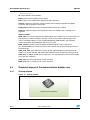
1
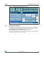
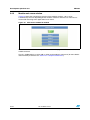
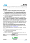
Development platform overview
Figure 1.
Development platform overview
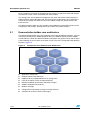
1.1
Software resources
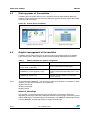
Figure 2 shows the different software and hardware resources used in the STM32
Demonstration Builder platform.
6/44
Doc ID 023271 Rev 1
UM1550
Development platform overview
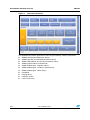
Figure 2.
1.2
STM32 software and hardware resources
Firmware architecture
The development platform is built with a modular architecture based on a FreeRTOS realtime operating system and STM32 graphical library. The system configuration and the
standard peripheral settings and configuration are made through the
STM32F2xx/STM32F4xx standard peripheral libraries.
Data used by the application is stored in the external USB Flash disk and the embedded
MicroSD Flash through a FAT file system (FatFS).
Doc ID 023271 Rev 1
7/44
Development platform overview
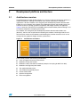
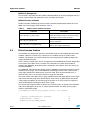
Figure 3.
UM1550
Firmware architecture
The development platform application is built using the following software components.
8/44
●
STM32F2xx Standard Peripherals Library
●
STM32F4xx DSP and Standard Peripherals Library
●
STM32 USB USB On-The-Go Host and Device Library
●
STM32 graphical library and extension
●
STM32 Audio Engine - Equalizer Library
●
STM32 Audio Engine - Loudness Control Library
●
STM32 Audio Engine - Mixer Library"
●
FreeRTOS
●
LibJpeg library
●
FatFS file system
●
LwIP TCP/IP stack
Doc ID 023271 Rev 1
UM1550
Development platform architecture
2
Development platform architecture
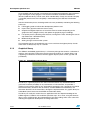
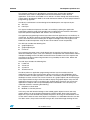
2.1
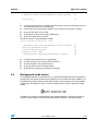
Architecture overview
The STM32 Demonstration Builder platform is a full set of software components based on a
module architecture, allowing each module to be reused separately in standalone
applications. All these modules are managed by the development platform demonstration
builder core, thus allowing new modules to be added dynamically and providing access to
common resources (storage, graphical component and widget, memory management).
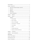
Figure 4 shows the architecture of the STM32 Demonstration Builder platform through a set
of software components composing the module.
The modules are managed by the development platform demonstration builder core
(Nucleus), which is then responsible for initializing the modules, initializing hardware and
GUI resources relative to the modules and initializing the common resources such as the
storage unit, the graphical widgets and the system menu.
Figure 4.
Architecture of modules
Each module provides the following functionalities.
●
Form and graphical aspect characteristics.
●
Method to startup the module.
●
Method to safely shut down the module (example: hot unplug for MS Flash disk).
●
Method to manage low-power mode.
●
The application body (task).
●
The module background process.
●
Distant control APIs.
●
Specific configuration.
●
Error management.
Doc ID 023271 Rev 1
9/44
Development platform architecture
2.2
UM1550
Folder organization
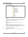
Figure 5.
Organization of folders
The project is composed of three main directories and organized as follows.
Libraries
This directory contains the STM32 graphical library and hardware abstraction layer, the
standard peripheral libraries, the host and device libraries, the STM32 USB OTG driver, the
CMSIS files and the STM32 standard peripheral driver.
Project
This directory contains the workspace and source files for the modules and the
demonstration builder core.
Utilities
This directory contains the STM32 EVAL boards drivers (LCD, SD card, buttons,
touchscreen...) and STM32 Audio Utilities & add-ons (mixer, equalizer...). It also contains
the open-source third-party software: file system FatFS used for the USB host and MicroSD
storage units, FreeRTOS, LwIP TCP/IP stack and LibJpeg library.
2.3
Development platform files
The development platform source files are located under the project folder as shown in
Figure 6.
10/44
Doc ID 023271 Rev 1
UM1550
Development platform architecture
Figure 6.
Development platform files
The demo sources are divided into four groups.
User
Contains the main, bsp and interrupt files.
Graphics
Contains the extension features of the graphical library and the initialization of the graphical
part of the development platform.
App
Contains the functional side of the modules relative to the main task.
Modules
Contains the core manager of the module and the graphical aspect, as well as the
windowing management of the modules.
Project settings
A folder per tool chain containing the project settings and the linker files.
Doc ID 023271 Rev 1
11/44
Development platform architecture
Table 2.
Demo source files
Group
User
Graphics
UM1550
Files/directory
Description
main.c
Contains the entry point to the development
platform and implements the background task
bsp.c
Contains the initialization function to the specific
board features
stm32fxxx_it.c
Contains the STM32 interrupts handler
Fatfs_drv
FatFS disk I/O interface for the USB disk Flash and
the MicroSD interfaces
gl_ext.c
Contains the extensions to the graphical library and
the new widgets core
gl_mgr.c
Contains the development platform graphical library
manager and the input events handler
Message.c
Modules messages form
mod_core.c
Demonstration Builder core manager
usbh_usr.c
User callbacks for the USB host
File_utils.c
Global file manager APIs
LibJpeg_utils.c
LibJpeg library user APIs
Mem_utils
Memory management extension: set of APIs to
allocate/de-allocate memory in the SRAM, used as
extra space for data processing. For example:
decoding of images/audio files
Str_utils.c
String formatting wrapper APIs
Time_utils.c
Time and date calculation method and algorithm
STM32Fxxx
Board and device-specific library and system
utilities
mod_xxx.c
Module core
app_xxx
Application implementation relative to xxx module
Manager
Lib
Devices
Modules
12/44
Doc ID 023271 Rev 1
UM1550
3
Development platform core
Development platform core
The development platform core is the software component in charge of initializing and
monitoring the demonstration builder application and the various loaded modules. The
development platform core allows you to perform the following tasks.
●
Initializes the LCD and the different input devices (joystick, buttons and touch screen).
●
Manage the graphical system menu and the actions relative to the graphical events.
●
Probe the input events on the touch screen.
●
Initialize the modules and monitor their internal state.
●
Initialize the storage units.
●
Handle the low-power mode.
●
Manage the core and module configurations by saving and retrieving the settings
information from the system backup.
●
Manage the background tasks of the modules.
Figure 7.
Development platform core tasks
-ODULESMANGERAND"30INITIALIZATION
!DDMODULES
3TART'RAPHICAL,IBRARY MODULE)NITIALIZATIONPHASE
3TARTTHE,IBRARIESANDTHIRDPARTIESSTACKS
3HOWMAINMENU
4OGGLE,EDS
1UERYINPUTSEVENTS
0ERIODICTASKS
0ROCESS'5)EVENTSANDUPDATEWIDGETSSTATE
(ANDLE-ODULES,OWPOWER
#HECKSYSTEMSETTINGSCHANGES
(ANDLEMODULESBACKGROUNDTASKS
-36
The demonstration builder core is based on FreeRTOS. A main task called background
constitutes the heart of the development platform. This task loads the different modules and
updates the graphical state and the input events following the user actions on the touch
screen.
Doc ID 023271 Rev 1
13/44
Development platform core
UM1550
Once a module is launched, the background task switches to supervisor mode and monitors
the child task, which is then launched by the active module.
The storage units are fundamental components that store and retrieve media from/to the
USB Flash disk and the MicroSD card. The file manager module allows you to explore the
content of the storage unit and then launch the audio or image files directly from the file
browser frame.
The demonstration builder core also provides some additional functionalities relative to the
configuration and settings, allowing them to be saved to the backup memory.
3.1
Demonstration builder core architecture
The demonstration builder core is the backbone of the entire development platform. It is built
around the FreeRTOS, the STM32 graphical library, the USB host library and the STM32
standard library. It loads the different modules and updates the graphical state and the input
events following the user actions on the touch screen. The core is composed of the following
elements (Figure 8).
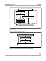
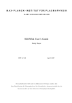
Figure 8.
14/44
Architecture of the demonstration builder core
●
Application startup task
●
Graphical library with extensions
●
USB host library and MicroSD driver for storage units
●
LCD Hal and touch screen and joystick drivers
●
RTOS (FreeRTOS) and memory allocation manager
●
STM32 standard firmware library
●
Modules manager
●
Configuration and settings manager in backup memory
●
Common GL resources (icons and images)
Doc ID 023271 Rev 1
UM1550
Development platform core
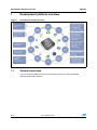
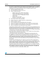
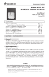
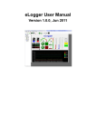
Figure 9.
Demonstration modules
Application startup task
Storage
(USB MS and
SD card)
Module
1
Module
3
Module
4
Module
2
Module
manager
STM32 Eval board
driver
LCD
Touchscreen drivers
Module
1
FreeRTOS
GUI
library
System
modules
STM32 Standard Firmware
Library
Drivers
Main module (kernel)
Additional modules
3.1.1
Application startup
The development platform starts by initializing the main background task.
int main(void)
{
NVIC_PriorityGroupConfig(NVIC_PriorityGroup_4);
/* Create background task */
xTaskCreate(Background_Task,
"Background Task",
Background_Task_STACK,
NULL,
Background_Task_PRIO,
&Task_Handle);
/* Start scheduler */
vTaskStartScheduler();
}
The background task starts by initializing the BSP to launch the LCD, touch screen and
joystick so as to handle the input events. It then loads the user modules in the demonstration
builder core module list to be handled later by the demonstration builder core, and initializes
the console to gather the demonstration builder core and module messages during the
startup phase and while the modules are running.
Doc ID 023271 Rev 1
15/44
Development platform core
UM1550
Once the BSP and the console are initialized, the background task displays the initialization
page showing the startup progress state and then initializes the different middleware
libraries (USB host library, TCP/IP stack, RTC and MicroSD). Finally, the second LUN (SD)
is mounted (note that the first LUN [USB] is mounted during the USB host initialization
phase).
After the initialization phase, the background task starts periodically monitoring the following
processes.
●
LED toggling used to indicate the development platform state.
●
Input events (joystick and touch screen states)
●
Graphical background process to launch the firmware actions depending on the
graphical events (widgets events) and update the graphical page accordingly.
●
Low power process (disabling some features, turning off the LCD, switching the core to
stop mode after a defined timeout).
●
Module background tasks
●
Setting changes of the monitor system.
The background tasks run periodically every 10 ms and have the highest priority. Certain
other tasks are delayed by way of a counter.
3.1.2
Graphical library
The STM32’s embedded graphic library is a firmware package that contains a collection of
routines, data structures and macros covering the main features of a graphic library and
supporting an HID device to interact with the graphic objects (touch screen, joystick and
pushbutton).
Figure 10. Embedded graphical library
The library is a general-purpose one and can be executed on any 8/16/32-bit CPU to
guarantee maximum portability of any architecture or LCD controller, and provides a
graphical user interface (GUI) for any application that operates with a graphical LCD. While
the firmware library functions with all currently available STM32 microcontrollers, this
document describes the firmware library through the implementation of a graphic library for
embedded systems based on the STM32 microcontroller family.
The library can easily be used in the user application with no in-depth knowledge of the
STM32 registers, FSMC or I2C read/write operation steps. As a result, using the firmware
library saves significant time that would otherwise be spent coding, while at the same time
reducing the application development and integration costs.
16/44
Doc ID 023271 Rev 1
UM1550
Development platform core
The firmware architecture is developed as separate layers and the HAL (hardware
abstraction layer) makes it independent from the microcontroller used in the final
application. A set of fonts is included: 8 x 12 and 16 x 24. Even though the firmware library
source code is developed in ANSI-C, the code architecture follows an OOP (object oriented
programming) approach.
The library’s architecture has been designed and developed as two separate layers.
●
API layer
●
HAL layer
This type of architecture improves the code’s re-usability by splitting the application
programming interface code (fully portable and re-usable) from the hardware abstraction
layer code (hardware dependent and written in the LCD library).
The application programming interface layer allows the final application to use the library as
a black box. The library firmware encapsulation feature and exported API enable full control
of the LCD and touch screen without prior in-depth knowledge of the LCD registers and
FSMC/I2C read/write operation steps for the LCD and touch screen respectively.
The API layer includes the following files.
●
graphicObject.c/h
●
graphicObjectTypes
●
cursor.c/h
The hardware abstraction layer is built directly into the specific LCD firmware library and
allows the build-upon layers, such as the API layer, to implement their functionalities without
in-depth knowledge of the LCD, MCU and touchscreen controller used. This improves the
reusability of the library code and guarantees easy portability to other LCDs, MCUs and
touchscreen controllers.
The HAL layer includes the following files.
●
LcdHal.c/h
●
TscHal.c/h
●
JoyHal.c/h
●
Touchscreen.c/h
The library offers an application programming interface layer that enables the final
application to create pages of the graphic objects and easily use the STMPE811 touch
screen controller. An OOP approach is used and it is therefore possible for the application
developer to create and use one or more instances of a graphic object and work with pages
of the object without having to write the code to display the graphic objects every time the
application changes its focus to another page. Graphic object structures are seen by the
application as objects with encapsulated properties and methods. In the end, they are
advanced structures containing the following:
●
Properties as data fields
●
Methods as function pointers
In this way, each API function belongs to the related graphic object instance and many
graphic objects can be managed simultaneously without conflict. Every type of graphic
object has a pre-event function that provides the process to change its visualization on the
screen and the internal status of the object. For example, in a ComboBox when the user hits
the "down arrow", the pre-event function changes the associated image showing the one
Doc ID 023271 Rev 1
17/44
Development platform core
UM1550
associated with the highlighted event for a few moments, and sets the next option in the list
as active.
This function is predefined for each type of object and very useful in minimizing the
developer’s workload. In this way, the developer need only place graphic objects on the
screen page and write a function event that is called after the pre-event function, when a
touch/click event occurs between the object’s coordinates area.
The library exports the following public and global API functionalities to create the graphic
objects’ type structure instance and set/get the relative properties.
18/44
●
NewLabel function
●
NewButton function
●
NewSwitch function
●
NewCheckbox function
●
NewIcon function
●
NewRadioButtonGrp function
●
AddRadioOption function
●
NewSlidebar function
●
NewHistogram function
●
NewGraphChart function
●
NewComboBoxGrp function
●
AddComboOption function
●
Create_PageObj function
●
AddPageControlObj function
●
DestroyPageControl function
●
DestroyPage function
●
Set_Label function
●
Get_Label function
●
Get_SlidebarValue function
●
SetGraphChartPoints function
●
SetHistogramPoints function
●
GetObjStatus function
●
GetComboOptionActive function
●
ResetComboOptionActive function
●
GetComboOptionLabel function
●
SetComboOptionLabel function
●
SetIconImage function
●
ShowPage function
●
RefreshPage function
●
RefreshPageControl function
●
ChangePage function
Doc ID 023271 Rev 1
UM1550
3.1.3
Development platform core
Graphical extensions
Additional graphical components, features and functionalities have been added to enrich the
graphical API set so as to improve the graphical aspect of the modules. These components
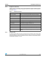
are listed in Table 3.
Table 3.
Graphical extensions
Function
3.1.4
Description
AddIconControlObj
Add an icon menu with event handler and caption in the page
GL_SetMenuItem
Add a list menu in the page
GL_RefreshControlNow
Refresh a graphical control in the page immediately
GL_RefreshLabel
Refresh a label caption immediately
GL_CenterCaption
Center a text in a buffer
GL_SetPageHeader
Add a page header to show the page caption
GL_SetChecked
Set or reset a check box during graphical construction
GL_IsChecked
Check whether a checkbox is checked or not
GL_AddScroll
Add a scroll bar in a page
GL_AddSmallIconControlObj
Add a small icon menu with event handler and caption in the page
GL_AdjustColor
Invert pixel color (RGB to BGR) during bitmap drawing
GL_AddCalendar
Add a calendar widget
GL_UpdateCalendar
Update a calendar widget by changing the day, month or year in
run-time
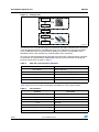
Storage units
The demonstration builder core offers two storage units that could be used to retrieve audio
and image media or to save captured images from the camera. The two units are initialized
during the development platform startup phase and are available to all the modules during
the development platform’s run time.
Doc ID 023271 Rev 1
19/44
Development platform core
UM1550
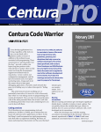
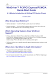
Figure 11. Storage units
SDIO driver
FS driver
Unit 0 MicroSD
File system
FS driver
USB Host
stack
Unit 1 USB Flash disk
MS30271V1
The two units are accessible through the standard I/O operations offered by the FatFS used
in the development platform. The USB disk Flash unit is identified as Unit 0 and available
only if a USB disk Flash is connected to the USB FS connector. The MicroSD Flash is
identified as Unit 1 and available only if the MicroSD card is connected.
The units are mounted automatically when the physical media is connected to the connector
on the board. The functionalities implemented in the file system interface to manage the
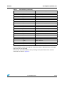
physical storage units are given in Table 4.
Table 4.
MSC file system interface functions
Function
disk_initialize
Description
Initialize disk drive
disk_read
Interface function for a logical page read
disk_write
Interface function for a logical page write
disk_status
Interface function for testing if unit is ready
disk_ioctl
Control device dependent features
Table 5 gives the full set of API functionalities provided by the file system interface.
Table 5.
API functions
Function
f_mount
Register/unregister a work area
f_open
Open/create a file
f_close
Close a file
f_read
Read file
f_write
Write file
f_lseek
Move read/write pointer, expand file size
f_truncate
20/44
Description
Truncate file size
Doc ID 023271 Rev 1
UM1550
Development platform core
Table 5.
API functions (continued)
Function
f_sync
Description
Flush cached data
f_opendir
Open a directory
f_readdir
Read a directory item
f_getfree
Get free clusters
f_stat
Get file status
f_mkdir
Create a directory
f_unlink
Remove a file or directory
f_chmod
Change attribute
f_utime
Change timestamp
f_rename
Rename/move a file or directory
f_mkfs
Create a file system on the drive
f_forward
f_chdir
Forward file data to the stream directly
Change current directory
f_chdrive
Change current drive
f_getcwd
Retrieve the current directory
f_gets
Read a string
f_putc
Write a character
f_puts
Write a string
f_printf
Write a formatted string
For the FatFS file system, the page size is fixed to 512 bytes. USB disk flashes with higher
page sizes are not supported.
Unit 0 is built around the USB host library working in full-speed mode and its software
architecture is shown in Figure 12.
Doc ID 023271 Rev 1
21/44
Development platform core
UM1550
Figure 12. Software architecture of Unit 0
!PPLICATION &ILESYSTEM&AT&3
&ILESYSTEMDRIVER
-3#CLASSCORE
3#3)COMMANDS
"/4MACHINE 53")/ REQUESTS
-36
Unit 1 is built around the SD driver using the SDIO peripheral and its software architecture is
shown in Figure 13.
Figure 13. Software architecture of Unit 1
!PPLICATION
&ILESYSTEM&AT&3
&ILESYSTEMDRIVER
3$DRIVER
-36
The FatFS is based upon the USB host mass storage class and the SD driver to allow
abstract access to the physical media through standard I/O methods.
22/44
Doc ID 023271 Rev 1
UM1550
Development platform core
The FatFS is a generic FAT file system module for small embedded systems. It is written in
compliance with ANSI C and completely separated from the disk’s I/O layer. Therefore, it is
independent of the hardware architecture and has the following specific features.
●
Windows-compatible FAT file system
●
Very small footprint for code and work area
●
Various configuration options:
–
Multiple volumes (physical drives and partitions)
–
Multiple ANSI/OEM code pages including DBCS
–
Long file name support in ANSI/OEM or Unicode
–
RTOS support
–
Multiple sector size support
–
Read-only, minimized API, I/O buffer ...
●
FAT sub-types: FAT12, FAT16 and FAT32
●
Number of open files: unlimited, depends on available memory
●
Number of volumes: up to 10
●
File size: Depends on FAT specifications (up to 4 G-1 bytes)
●
Volume size: Depends on FAT specifications (up to 2 Tbytes on 512 bytes/sector)
●
Cluster size: depends on FAT specifications (up to 64 kbytes on 512 bytes/sector)
●
Sector size: depends on FAT specifications (up to 4 kbytes)
File operations to different volumes are always re-entrant ant can work simultaneously. File
operations to the same volume are not re-entrant but can also be configured to be accessed
by several file instances in a safe way with the _FS_REENTRANT option. In this case, the
OS-dependent synchronization object control functionalities (ff_cre_syncobj, ff_del_syncobj,
ff_req_grant and ff_rel_grant) must be added to the project.
When a file function is called while the volume is in use by another task, the file function is
suspended until that task leaves the file function.
If the wait time exceeds a period defined by _TIMEOUT, the file function aborts with
FR_TIMEOUT. The timeout feature may not be supported on some RTOS. There is an
exception for the f_mount and f_mkfs functionalities since these functions are not re-entrant
to the same volume. When these functions are used, all other tasks must close the
corresponding file on the volume and avoid accessing the volume. Note that this section
describes the re-entrance of the FatFS module itself. The low-level disk I/O layer must also
be re-entrant.
By default, the FatFS module does not support the sharing of controls of duplicated file
accesses. Sharing is permitted when an open operation to a file is in read mode only. The
duplicated open operation in write mode to a file is always prohibited and the open file must
not be renamed or deleted, or the FAT structure on the volume may collapse. The file
sharing control may also be available when _FS_SHARE is set to 1 or greater. The value
specifies the number of files to manage simultaneously. In this case, if any open, rename or
remove operation violates the file sharing rule described above, the file function fails with
FR_LOCKED. If the number of open files is larger than that specified in _FS_SHARE, the
f_open function fails with FR_TOO_MANY_OPEN_FILES.
Doc ID 023271 Rev 1
23/44
Development platform core
3.1.5
UM1550
LCD display and HMI inputs
The graphical hardware abstraction layer (HAL) controls the TSC, LCD and JOYSTICK
controllers using the following files.
●
LcdHal: HAL layer file. Contains all the LCD basic API declarations (STM32 for this
delivery).
●
JoyHal: HAL layer file. Contains all the joystick management function declarations.
●
TscHal: HAL layer file. Contains all the touch screen management function declarations
of the TSC controller used by the application.
The STM32 graphic library uses the HAL layers mentioned above to monitor the graphical
pages and control actions depending on the user action. The GL_Background_Handler ()
function is used by the background task to monitor the HID events in polling mode every
50 ms.
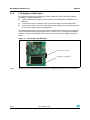
Figure 14. LCD display and HMI inputs
LCD + touch screen
Joystick + user buttons
Note:
24/44
The joystick can be disabled using the general configuration page of the system module.
Doc ID 023271 Rev 1
UM1550
3.1.6
Development platform core
RTOS and memory management
The development platform is built around the FreeRTOS real-time operating system.
FreeRTOS is a scaleable real-time demonstration builder core designed specifically for
small embedded systems. Its highlights include:
●
FreeRTOS demonstration builder core with preemptive, cooperative and hybrid
configuration options.
●
Official support for 27 architectures (counting ARM7 and ARM Cortex M3 as one
architecture each).
●
Support of the Cortex M3 memory protection unit (MPU) by the FreeRTOS-MPU.
●
Small, simple and easy-to-use design. Typically a demonstration builder core binary
image will be in the region of 4 to 9 kbytes.
●
Very portable code structure predominantly written in C.
●
Support of both tasks and co-routines.
●
Queues, binary semaphores, counting semaphores, recursive semaphores and
mutexes for communication and synchronization between tasks, or between tasks and
interrupts.
●
Mutexes with priority inheritance.
●
Support of efficient software timers.
●
Powerful execution traces functionality.
●
Stack overflow detection options.
●
Pre-configured demo applications for selected single-board computers allowing 'out-of
the-box' operation and fast learning curve.
●
Free forum support, or optional commercial support and licensing.
●
No software restriction on the number of tasks that can be created.
●
No software restriction on the number of priorities that can be used.
●
No restrictions imposed on priority assignment - more than one task can be assigned
the same priority.
●
Free development tools for many supported architectures.
●
Free embedded software source code.
●
Royalty free.
●
Cross-development from a standard Windows host.
The heap2 scheme of FreeRTOS is used for memory allocation management. This scheme
uses a best-fit algorithm that allows previously allocated blocks to be freed. It does not,
however, combine adjacent free blocks into a single large block. The total amount of
available RAM is set by the definition configTOTAL_HEAP_SIZE which is defined in
FreeRTOSConfig.h.
3.1.7
Modules manager
The modules manager is basically the firmware component responsible for initializing the
platform BSP, modules and the libraries used by them. It also provides common helper
functions that can be used by all the modules.
Hardware initialization
The modules manager starts by initializing the console and BSP at the beginning of the
background task of the demonstration builder core using the following function.
Doc ID 023271 Rev 1
25/44
Development platform core
UM1550
void MOD_PreInit(void)
{
MOD_counter = 0;
CONSOLE_Init();
CONSOLE_LOG("[MOD] Module Manager running....");
/* Init Board specific hardware */
BSP_Init();
}
Library initialization
The modules manager initializes the different middleware libraries and indicates their
startup progress in the GUI startup page and mounts the storage unit 1 (SD).
void MOD_LibInit(void)
{
( …)
GL_State_Message("xxx Library Starting...");
Xxx_LibInit();
GL_State_Message("xxx Library Started.");
(…)
SD_Init();
if ( f_mount( 1, &MSD_fatfs ) != FR_OK )
{
/* efs initialisation fails*/
CONSOLE_LOG("[FS] Cannot initialize FS on drive 1.");
}
else
{
CONSOLE_LOG("[FS] FS on drive 1 initialized.");
}
}
Adding modules
The modules are defined in a structure that is used during the main menu startup and the
module run time. Since the main menu uses several GUI resources and thus a big amount
of data, the adopted strategy regarding the main menu has been to free resources when
moving to the next page (modules page) and draw the menu page when returning from the
modules page. For this, the modules structures should be stored in a table that enables
retrieving them when needed.
MOD_table is used to keep the module structure pointers while MOD_counter tracks the
number of loaded modules. To load a module inside the modules table, the
MOD_AddModule function is used.
Note:
26/44
Each module should have a unique ID, otherwise the second module with the same ID will
not be loaded and the MOD_AddModule function returns an error.
Doc ID 023271 Rev 1
UM1550
3.1.8
Development platform core
Configuration and settings management
The global demonstration settings are managed at startup while the module settings are
applied during the module’s initiation phase. The various settings for each module are saved
as 32-bit words inside the RTC backup registers using the following functions.
void MOD_GetParam(uint16_t mem_base , uint32_t *cfg);
void MOD_SetParam(uint16_t mem_base , uint32_t *cfg);
Each module can have one or more memory locations to save its internal parameters. For
easy use, a bit field structure could be defined to give access to the module settings.
3.1.9
Common GL resources
All the common graphic icons and images used by the modules and the demonstration
builder cores are declared in the demonstration builder’s core layer and exported to the
entire platform firmware through the gl_res.h file. Shared or exported functionalities between
modules or between modules and the demonstration builder core are defined in the
mod_xxx.h file Implementing these APIs.
Example
IMAGE_DirectEx (GL_Page_TypeDef* pParent, uint8_t *file_path): allows the user to launch
the Image browser subpage in the image module through the file manager module when a
file in the browser is selected.
The mod_xxx.h file also exports the shared variables, defines and macros used by the entire
platform firmware.
Example
The CONSOLE_LOG (msg) macro is used by all the modules and the demonstration builder
core to add messages in the console, regardless of whether the console is displayed or
deactivated. Messages are saved in the console cache and displayed when the console
page is activated and displayed.
3.2
Application programming interface
The demonstration builder core communicates with the top level application and the
application modules through the graphics and the modules’ manager APIs. The application
must use the demonstration builder core APIs to have access to the modules’ functionalities.
This allows separating the modules and the application when a standalone application
based on a module is to be created from the open-source platform development package.
3.2.1
Graphic APIs
The graphic APIs are a set of functions and methods that provides access to the GL
resources and controls the visual aspects of the open-source platform development
package.
Doc ID 023271 Rev 1
27/44
Development platform core
Table 6.
UM1550
Graphic API functions
Functions
Description
void GL_Startup (void)
Show the initialization progress as the first display
screen
uint32_t GL_Init (void)
Initialize the screen, display the main menu and
apply the retrieved data from the backup memory
Void GL_ShowMainMenu(void)
Display the main menu, this function can be used by
module to return to the demonstration menu page
Void GL_Handle_Inputs(void)
Handle the HMI inputs (joystick and touch screen)
void GL_State_Message (uint8_t *msg)
Display the initialization progress state when loading
modules and libraries
void GL_HandleSystemSettingsChange (void) Apply settings if they were changed
28/44
void GL_ShowConnectivityGroup (void)
Display the connectivity group page
void GL_ShowMultimediaGroup (void)
Display the multimedia group page
void GL_ShowUtilitiesGroup (void)
Display the utilities group page
Doc ID 023271 Rev 1
UM1550
3.2.2
Development platform core
Modules manager APIs
The modules’ manager APIs is a set of functions that handles the demonstration builder’s
core process and functions.
Table 7.
Modules manager API functions
Functions
3.3
Description
uint8_t MOD_AddModule(MOD_InitTypeDef
*module, uint8_t group)
Add a module to the modules list
void MOD_SetParam(uint16_t ID , uint32_t
*cfg)
Save general or module parameters in the backup
memory
void MOD_GetParam(uint16_t ID , uint32_t
*cfg)
Return general or module parameters in the backup
memory
void MOD_NullFunc(void)
Empty function used when a control in page uses a
callback with no specific action
void MOD_PreInit(void);
Initialize the BSP and the demonstration builder core
events console
void MOD_LibInit(void);
Initialize the libraries and show the startup phase
progress and mount the storage Unit 1 (SD)
void MOD_HandleModulesBackground (void)
Handle module background processes in the main
background task
void MOD_HandleModulesClanup (void)
Handle module cleanup processes in the USB
disconnect callbacks (usbh_usr.c)
void MOD_RegisterClickHandler(void
(*pEventHandler)(void),
GL_Coordinate_TypeDef gRect)
Associate a click event in a predefined screen area
void MOD_UnRegisterClickHandler(void)
Dissociate a click event in a predefined screen area
MOD_fClickHandler(void)
Handle click event handler in the main background
task
void vApplicationMallocFailedHook( void )
Memory management error callback
Application data structures and variables
MOD_InitTypeDef
typedef struct _MOD_InitTypeDef
{
uint16_t id;
uint16_t rev;
uint8_t
*name;
uint8_t
*icon;
void
(*startup)(void);
void
(*background)(void);
void
(*cleanup)(void);
}
Doc ID 023271 Rev 1
29/44
Development platform core
UM1550
MOD_InitTypeDef;
Id: unique identifier of the module.
Name: pointer to the module name in ASCII.
Icon: pointer to the module icon (bmp format, 50 x 50 pixels).
Startup: callback to launch the startup function of the module to initialize the module
resources and the graphical constructor.
Background: callback to launch the background functions of a module.
Cleanup: callback to launch the cleanup functions of a module when a storage unit is
removed.
Global variables
MOD_table: an array that keeps the loaded modules in the memory so as to have access to
their resources anytime during the run time, and that also enables redrawing the main
menu. The MOD_table has a size of MAX_MODULES_NUM modules, the maximum
number of modules being defined in the mod_core.h file.
MOD_counter: holds the current number of loaded modules and is used by the
GL_ShowMainMenu to call the main menu and calculate exactly the position of the icon in
the menu page.
USB_OTG_Core: main USB core structure for the USB host libraries (configured in FS
mode). It is used to initialize and monitor the USB host library and thus the storage unit 0.
USB_Host: variable that holds the host process states (enumeration, control state machine,
class and user callbacks).
USB_fatfs: Unit 0 storage unit file system structure.
MSD_fatfs: Unit 1 storage unit file system structure.
3.4
Graphical aspect of the demonstration builder core
3.4.1
Startup window
Figure 15. Startup window
STM32 System Initialization...
30/44
Doc ID 023271 Rev 1
UM1550
Development platform core
The startup window is launched by the GL_Startup function to indicate that the initialization
phase is going to start. After this initialization step, the message on the screen changes.
The user can use the GL_State_Message in the MOD_LibInit function to view the startup
progress of the libraries and stacks.
Figure 16. Start initialization
USB host starting
The user should at least indicate the beginning and the end of the initialization phase of a
library or stack and also add a message in the console cache so that if an error occurs, the
startup phase can be analyzed.
3.4.2
Main menu window
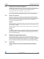
Figure 17. Main menu window
Note:
The icons used in this demonstration are taken from
http://commons.wikimedia.org/wiki/Crystal_Clear
Modules Zone: the click event on the icon launches the module startup handler.
System Time and Date: the update of the time and date are done by the kernel background
task and can be re-adjusted in the Calendar Modules > Settings menu.
Group Zone: the group zone contains the groups of modules. A group is set of modules that
have the same functions.
The main menu holds the entire group of modules and the module icons of the highlighted
group and enables you to launch the module startup function when the corresponding icon
is clicked by way of the joystick’s middle button or by pressing it on the touch screen.
Doc ID 023271 Rev 1
31/44
Development platform core
3.4.3
UM1550
Module main menu window
Figure 18 shows the main display page for all the modules. Actions 1 to 3 can be
customized by the user depending on the module’s functions while the last menu item is
reserved for returning to the application’s main menu.
Figure 18. Main menu window for module
The name and icon shown at the top of the module’s main page should be retrieved from the
module structure.
The GL_SetMenuItem is used to add an action to the module’s main menu (for more details
about function parameters see Section 3.1.3: Graphical extensions).
32/44
Doc ID 023271 Rev 1
UM1550
Application modules
4
Application modules
4.1
What is a module?
A module is a set of functionalities with specific characteristics declared in one or more files
that manage the STM32’s low-level resources and that provide common and specific
functions.
Figure 19. Architecture of modules
Each module should provide the following functionalities and characteristics.
4.2
●
Characteristics of its form and graphical aspect.
●
Method to start up the module.
●
Method to safely shut down the module (for example: hot unplug for MS Flash disk).
●
Method to manage the low-power mode.
●
The application body (task).
●
The module’s background process.
●
Distant control APIs.
●
Specific configurations.
Module architecture
A module is composed of two main parts: the graphical aspect and the set of functionalities
that it offers.
The graphical aspect is the used frame or page with a set of visual controls used to launch
and monitor the module’s functionalities. The module’s graphical definition, page draw
methods and action callbacks are declared in the MOD_xxx.c file with xxx being the name of
the module.
The functionality of the module is the interaction protocol between the STM32 resources
and the demonstration builder core to offer specific actions. These actions are launched
from the graphical control actions and located in the app_xxx.c file. Although the app_xxx.c
file is the main file to execute the action defined in the module’s page control, other files
could be used to build multilayer functionalities if required by the module.
Doc ID 023271 Rev 1
33/44
Application modules
4.3
UM1550
Start-up phase of the modules
A module goes into action when its icon is clicked in the main menu window. When the
module’s icon is selected by one of the two HMI inputs (joystick or touch screen) the module
starts the callback function.
Figure 20. Startup phase of modules
4.4
Graphic management of the modules
A module may be composed of one or several pages managed internally by the module
page control actions. Each module should at least include the following three functions.
Table 8.
Module functions for graphic management
Function
Note:
Description
void MODULE_SwitchPage(GL_Page_TypeDef*
pParent, uint32_t PageIndex)
Used to switch between module pages
void MODULE_CreatePage(uint8_t Page)
Used to add the page controls. The control event
handler is implemented depending on the control
action
Void MODULE_Startup (void)
Activated when the module icon in the main
menu is selected
The module prefix "MODULE_" should have the name of the module. For example, for audio
modules, the above three functions are respectively:
AUDIO_SwitchPage
AUDIO_CreatePage
AUDIO_Startup
MODULE_SwitchPage
This function is used to kill the parent page (active page) and create the child page
depending on the page index. After calling this function, the parent page resources are freed
and the child page is created and shown on the display. The MODULE_SwitchPage function
uses the MODULE_CreatePage function to create the child page.
34/44
Doc ID 023271 Rev 1
UM1550
Application modules
A module page can return to the application main menu by calling:
MODULE_SwitchPage (ModulePageN, PAGE_MENU);
ModulePageN is the current active module page.
MODULE_CreatePage
The MODULE_CreatePage is used to create the different pages used in the module. Action
callbacks are implemented depending on the page control type. An example of
implementation is shown in the following code.
static void MODULE_CreatePage(uint8_t Page)
{
GL_PageControls_TypeDef* item;
GL_SetBackColor( GL_White );
GL_SetTextColor( GL_Blue );
switch (Page)
{
case MODULE_MAIN_PAGE:
(…)
break;
case MODULE_PAGE1:
(…)
break;
case MODULE_PAGE2:
(…)
break;
default:
break;
}
}
The pages should be allocated dynamically using the memory management process as
follows.
ModuleMainPage = malloc(sizeof(GL_Page_TypeDef));
Create_PageObj(ModuleMainPage);
MODULE_Startup
This function is the callback of the module icon control in the main menu. It is used to
initialize the module’s structures and data, and display the module’s main menu by calling
the MODULE_SwitchPage function.
MODULE_SwitchPage(GL_HomePage, MODULE_MAIN_PAGE);
MODULE_Cleanup
This function is the callback of the module called in the USB host disconnect event to free
FS-dependent resources.
Doc ID 023271 Rev 1
35/44
Application modules
UM1550
MODULE_Background
This function is the callback of the module called periodically in the main background task. It
can be used to refresh the application status and some GL controls.
MODULE action callbacks
Buttons and other module page control actions should be implemented statistically in the
MOD_xxx.c file using the rules outlined in Table 9.
Table 9.
Module action callback functions
Functions
4.5
Description
static void return_to_menu (void)
Should be implemented in all the modules and
enable the module to return to the main menu by
selecting the "return" item in the menu.
static void goto_pageN (void)
Used to move to pageN when the corresponding
action is activated.
static void return_from_pageN (void)
Used to close the current module sub-page and
return to the module’s main menu.
Direct access feature
The modules are designed to operate in standalone mode and are independent from other
modules. However, in some cases, some parts of a module may be re-used by other
modules. For example, the camera viewer uses the image browser module to display the
image captured previously.
Such a feature is called direct access and generally named MODULE_DirectEx. Depending
on the action of the direct access function, the parameters may defer from module to
module. The MODULE_DirectEx function is exported in the modules’ file to be seen by all
the loaded modules.
The MODULE_DirectEx function directly calls the MODULE_CreatePage function to create
the direct access page, and not the MODULE_SwitchPage function. This is because the
caller page should not be killed and its resources freed, but instead should be put in a
dormant state, that is, its resources kept but its page not displayed.
The return action of the direct access page should kill the parent page (direct access page)
and restore the caller page to its default display state (active). A global pointer should be
used to keep the address of the caller page in memory so as to use it later to restore the
initial context before launching the direct access page.
This feature uses larger memory resources than normal access, so special care should be
taken when defining the heap size. A sample implementation of a direct access page is
shown in the following code.
void MODULE_DirectEx(GL_Page_TypeDef* pParent, void *params)
{
36/44
(*pParent).ShowPage(pParent, GL_FALSE);
(1)
ModuleBackPage = pParent;
(2)
MODULE_CreatePage(IMAGE_DIRECT);
(3)
Doc ID 023271 Rev 1
UM1550
Application modules
(*ModuleDirectPage).ShowPage(ModuleDirectPage, GL_TRUE);
(4)
DirectFunct();
(5)
}
●
(1) Put the parent page in a dormant state (the page is present in the memory but not
activated and controls are not displayed).
●
(2) Save the parent page pointer address to be used later to restore the context.
●
(3) Create the direct access page.
●
(4) Activate the direct access page and display it.
●
(5) Run the direct access process.
The return process is implemented as follows.
static void return_from_direct (void)
{
(*ModuleDirectPage).ShowPage(ModuleDirectPage, GL_FALSE); (1)
DestroyPage(ModuleDirectPage);
(2)
vPortFree(ModuleDirectPage);
(3)
ModuleDirectPage = NULL;
(4)
(*ModuleBackPage).ShowPage(ModuleBackPage, GL_TRUE);
(5)
}
4.6
●
(1) Deactivate the direct access page display.
●
(2) Free the direct access page control resources.
●
(3) Free the direct access page memory.
●
(4) Assign NULL to clear the page pointer.
●
(5) Restore the caller page context by activating it.
Background mode feature
The background feature is the ability to run an application without displaying the graphical
parent page. This feature enables some modules to run in parallel with other modules. It is
enabled from the global settings of the demonstration and launched by the corresponding
module itself. An example of use is to run the image browser while an audio file is being
played.
A module that supports the background mode should implement a command wrapper to
launch its actions without necessarily going through the module’s main page controls.
Doc ID 023271 Rev 1
37/44
Application modules
UM1550
Figure 21. Implementation of command wrapper
The command wrapper layer is only used when the background feature is enabled for this
module. This layer should not have any dependency with the module’s graphical
components and controls.
Typical use of the background feature includes the audio player and web server applications.
For example, an audio sample file could be played and controlled by the wrapper without
passing through the audio player’s graphical menu.
A module that implements the background feature should be able to disable the background
mode on the fly when launching the module from the module’s main menu, and the page’s
graphical aspect should be synchronized with the core functions.
For example, if an audio file is being played in background mode, when the audio player is
launched, the corresponding page should indicate the specificities of the sample currently
being processed (file name, progress…).
To implement the background feature, the following structure should be implemented in the
module.
typedef struct _BKGND_InitTypeDef
{
void
(*init)(void);
void
(*process)(uint8_t cmd, void *args);
void
(*quit)(void);
} BKGND _InitTypeDef;
Init: initialize the module’s core (function).
Process: launch the process corresponding to the cmd parameters; the args can take the
command arguments and parameters.
Quit: de-initialize the module’s core and quit the background mode.
If a module implements the background callback structure, this should then be exported to
the modules.h file as follows.
38/44
Doc ID 023271 Rev 1
UM1550
Application modules
extern
BKGND_InitTypeDef
module_ bkgnd_cb;
The module should also implement a method to synchronize the graphical controls with the
background module.
Void MODULE_GLSynch
4.7
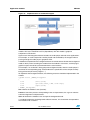
(void)
Distant control feature
The Distant control feature is the ability to launch and monitor a module from a distant host
PC through the web server’s HTML main page. The Distant control feature uses the
Ethernet module running in background mode. This feature is enabled by the Ethernet
module when the "Distant Control "menu item is selected.
Figure 22. Distant control feature
The modules running remotely should implement the command wrapper described in
Section 4.6: Background mode feature on page 37, that is, implement the background
callback structure as shown.
typedef struct _BKGND_InitTypeDef
{
void
(*init)(void);
void
(*process)(uint8_t cmd, void *args);
void
(*quit)(void);
} BKGND _InitTypeDef;
Doc ID 023271 Rev 1
39/44
Building a module
5
UM1550
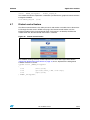
Building a module
Follow these steps to build a new module and add it to the STM32 demonstration builder.
1.
The first step is to use the mod_template.c file by changing the "template" prefix to the
user module. This file implements:
–
40/44
the module’s main structure to be used to add the module in the main.c file:
MOD_InitTypeDef mod_template =
{
MOD_TEMPLATE_UID,
MOD_TEMPLATE_VER,
"Templates",
(uint8_t *)Templates_icon,
Template_Startup,
Template_Background,
Template_Cleanup,
};
–
the module’s startup, cleanup and background callback functions with empty body.
–
the page switch and create functions, which should be updated by the user to add
additional pages and associate control actions following the application’s needs.
–
the first case of the page create function, which should be updated to add the
module’s main page items if needed, otherwise it can be replaced by custom page
controls.
GL_SetMenuItem(Page, "Item1", 0, goto_item1);
GL_SetMenuItem(Page, "Item2", 1, goto_item2);
GL_SetMenuItem(Page, "Item3", 2, goto_item3);
GL_SetMenuItem(Page, "Item4", 3, goto_item4);
GL_SetPageHeader(ImageMainPage , "Template Menu");
2.
Use the gl_template_res.c to add the module icon resources. The icons should be in a
bmp c-array file (which can be generated by the embedded resource editor GUI tools
provided with the STM32’s embedded graphic objects/touchscreen library package. For
more information about this tool and its use, refer to AN3128 STM32 embedded
graphic objects/touchscreen library.
3.
Implement the application functionality APIs in the app_template.c file and associate
them to the module page action callbacks.
4.
Export the module’s unique ID (UID), the module version, the mod_xxx.c structure and
any other APIs used by other modules.
5.
Include the mod_xxx.h file in the main file and add the module to the core using the
following API: MOD_AddModule (&mod_xxx, YYYY_GROUP);
6.
Run the STM32 Demonstration Builder project in the used tool chain to add the new
module.
Doc ID 023271 Rev 1
UM1550
6
Removing a module
Removing a module
Follow these steps to remove a module from the STM32 demonstration builder.
1.
Remove or comment the mod_xxx.h include file in the main file and remove or
comment the module adding process (MOD_AddModule().
2.
Exclude from build the folders and groups related to the module to be removed.
3.
Compile the STM32 Demonstration Builder project in the used tool chain to remove the
module.
Doc ID 023271 Rev 1
41/44
Module development considerations
7
UM1550
Module development considerations
1.
Any interrupt that uses the FreeRTOS APIs must be set to the same priority as the
kernel (as configured by the configKERNEL_INTERRUPT_PRIORITY macro), or at or
below configMAX_SYSCALL_INTERRUPT_PRIORITY for ports that include this
functionality.
A special note for Cortex M3: Remember that Cortex M3 cores use numerically low
priority numbers to represent HIGH priority interrupts, which can seem counter intuitive
and is easy to forget! If you wish to assign an interrupt a low priority do not assign it a
priority of 0 (or other low numeric value) as this can result in the interrupt actually
having the highest priority in the system and therefore potentially make your system
crash if this priority is above configMAX_SYSCALL_INTERRUPT_PRIORITY.
2.
42/44
When using the write operation from the fatFS file system, the task calling to the f_write
API should have a higher priority compared to the main background one.
Doc ID 023271 Rev 1
UM1550
8
Revision history
Revision history
Table 10.
Document revision history
Date
Revision
01-Aug-2012
1
Changes
Initial release.
Doc ID 023271 Rev 1
43/44
UM1550
Please Read Carefully:
Information in this document is provided solely in connection with ST products. STMicroelectronics NV and its subsidiaries (“ST”) reserve the
right to make changes, corrections, modifications or improvements, to this document, and the products and services described herein at any
time, without notice.
All ST products are sold pursuant to ST’s terms and conditions of sale.
Purchasers are solely responsible for the choice, selection and use of the ST products and services described herein, and ST assumes no
liability whatsoever relating to the choice, selection or use of the ST products and services described herein.
No license, express or implied, by estoppel or otherwise, to any intellectual property rights is granted under this document. If any part of this
document refers to any third party products or services it shall not be deemed a license grant by ST for the use of such third party products
or services, or any intellectual property contained therein or considered as a warranty covering the use in any manner whatsoever of such
third party products or services or any intellectual property contained therein.
UNLESS OTHERWISE SET FORTH IN ST’S TERMS AND CONDITIONS OF SALE ST DISCLAIMS ANY EXPRESS OR IMPLIED
WARRANTY WITH RESPECT TO THE USE AND/OR SALE OF ST PRODUCTS INCLUDING WITHOUT LIMITATION IMPLIED
WARRANTIES OF MERCHANTABILITY, FITNESS FOR A PARTICULAR PURPOSE (AND THEIR EQUIVALENTS UNDER THE LAWS
OF ANY JURISDICTION), OR INFRINGEMENT OF ANY PATENT, COPYRIGHT OR OTHER INTELLECTUAL PROPERTY RIGHT.
UNLESS EXPRESSLY APPROVED IN WRITING BY TWO AUTHORIZED ST REPRESENTATIVES, ST PRODUCTS ARE NOT
RECOMMENDED, AUTHORIZED OR WARRANTED FOR USE IN MILITARY, AIR CRAFT, SPACE, LIFE SAVING, OR LIFE SUSTAINING
APPLICATIONS, NOR IN PRODUCTS OR SYSTEMS WHERE FAILURE OR MALFUNCTION MAY RESULT IN PERSONAL INJURY,
DEATH, OR SEVERE PROPERTY OR ENVIRONMENTAL DAMAGE. ST PRODUCTS WHICH ARE NOT SPECIFIED AS "AUTOMOTIVE
GRADE" MAY ONLY BE USED IN AUTOMOTIVE APPLICATIONS AT USER’S OWN RISK.
Resale of ST products with provisions different from the statements and/or technical features set forth in this document shall immediately void
any warranty granted by ST for the ST product or service described herein and shall not create or extend in any manner whatsoever, any
liability of ST.
ST and the ST logo are trademarks or registered trademarks of ST in various countries.
Information in this document supersedes and replaces all information previously supplied.
The ST logo is a registered trademark of STMicroelectronics. All other names are the property of their respective owners.
© 2012 STMicroelectronics - All rights reserved
STMicroelectronics group of companies
Australia - Belgium - Brazil - Canada - China - Czech Republic - Finland - France - Germany - Hong Kong - India - Israel - Italy - Japan Malaysia - Malta - Morocco - Philippines - Singapore - Spain - Sweden - Switzerland - United Kingdom - United States of America
www.st.com
44/44
Doc ID 023271 Rev 1