1
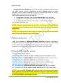
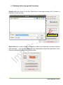
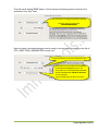
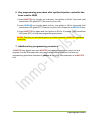
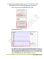
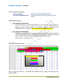
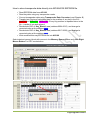
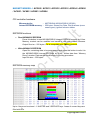
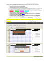
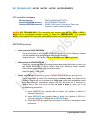
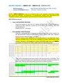
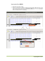
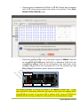
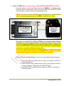
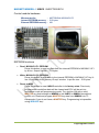
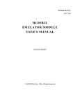
Advanced Scooter Workshop V2.82 User manual April 2013 [email protected] 1. Introduction Advanced Scooter Workshop is a K-line tool that incorporates ignition control unit (CDI) internal memory modification functions without cutting its plastic package, scrape sealant, soldering any wires or de-soldering memory IC. All you have to do is to connect four wires to controller connector. EEPROM Read/Write functions will help you: To copy data from faulty CDI controller into another (even used one) To read T5-11 formatted Key Data from CDI controller if all keys are lost To reset used CDI controller to the state of a brand NEW controller All functions works by K-line. NOTE1: This tool cannot program key by itself – it just reads out transponder key data that you have to program into T5 transponder using any suitable transponder programmer. NOTE2: You must to have at least 2 keys to complete key learning auto-procedure after CDI controller has been reset to NEW state. 2. System requirements USB / K-line interface of Advanced Scooter Workshop connects to desktop or laptop PC using any free USB port. It is powered from an external power supply (+12V / 800mA Min). Scooter battery can also be used as a power supply. Software runs on Windows 98, Windows XP, Windows Vista, Windows 7. 3. Supported CDI controller systems Software version V2.82 supports: MAGNETI MARELLI ACI100 / ACI50x / ACI60x with MC68HC05B8/B16 inside MAGNETI MARELLI IMM003/IMM006 with MC68HC05E6 (0F82B / 0G72G) inside MAGNETI MARELLI MIU1.XX / MIU2.XX with ST10F269-T3 inside MAGNETI MARELLI MIU G3 with Infineon SAK-XC2060 and 95320 inside MAGNETI MARELLI IAW15 with MC68HC11F1 (2E87J) inside EFI TECHNOLOGY ACII/AC2I/AC5I/AC8I/AC21I/AC23I with ST72 and 95040 EFI TECHNOLOGY AC19I / AC20I / AC25I / AC32I with ST72 MCU and 95080 NOTE3. If you have EFI TECHNOLOGY controller that is not in the list but it has the same connector and internal hardware architecture like one of these from the list, it is possibly supported, but you must to check out for power supply and K-line pins in the wiring diagram of the particular scooter. [email protected] 4. Connection NOTE4: Always observe polarity when connecting external power supply! Red terminal must be connected to +12V, black terminal to the GND. CDI CONTROLLER USB CABLE TO PC EXTERNAL 12V POWER SUPPLY [email protected] 5. Software hints and special functions Double click with mouse on the Key Data fields to save data to binary file. File name is created from the key data: Double click here Right Click with mouse to Copy calculated key data to the Clipboard (no need to transfer data manually – now you can Paste it to the transponder programmer application when preparing transponder key from calculated data): [email protected] Transponder Data Converter for TEMIC11 / T5-TYPE11. Can convert transponder reader data to EEPROM file format and prepares data from EEPROM file to use with transponder programmer. Copy/Paste operations are enabled in Key/File data fields – Right Click mouse to copy/paste data. Converter requires USB/K-line interface to be connected to the PC! External +12V power supply is not necessary. When to use Transponder Data Converter? Data may differ when reading same transponder key with several transponder readers: Enter data from transponder reader to the “Key” field and press button with blue arrows to realign data bits. [email protected] This will result finding 7D 5F bytes in the bit stream and placing them to the two first positions in the “Key” field: Press this button to realign transponder data bits. Key data will be formatted as 7D5FXXXXXXXXXXXX Now key data is formatted properly and is ready to be converted for writing to the file of CDI / INJECTION / IMMOBILIZER control unit: Press this button to convert transponder data Write data from this field to the EEPROM of CDI/INJECTION/IMMO control unit. Use 6 bytes for ACI100/500/600, IMM006 and EFI TECHNOLOGY (00 00 01 8A 29 16 in this example). Use all 8 data bytes for MIU controllers [email protected] 6. Key programming procedure after ignition/injection controller has been reset to NEW 1) Insert MASTER key (usually red or brown), turn ignition to ON for 2 seconds (until immobilizer LED goes OFF). Remove key from lock; 2) Insert SERVICE key (usually black or blue), turn ignition to ON for 2 seconds (until immobilizer LED goes OFF). Remove key from lock. Repeat for all SERVICE keys; 3) Insert MASTER key again and turn ignition to ON for 2 seconds (until immobilizer LED goes OFF) to close key programming procedure. NOTE5: First key you will switch ignition on will be stored as a MASTER regardless of its color. 7. Additional key programming procedure If MASTER key absent then read MASTER key data from particular control unit and program it to the T5 transponder using any transponder programmer. Perform key programming procedure described in chapter 6 using this T5 transponder as a MASTER key. [email protected] 8. How to know what is inside of your EFI TECHNOLOGY CDI controller if it is not in the list of supported controllers? Select system with external EEPROM of type 95080 Read EEPROM as 95080 If you have part number at addresses 0030-0035 but data in the range of 0100-03FF looks like in the picture (00 00 02 02 04 04 06 06 …) then the real type of external EEPROM is 95040 and there is ST72C334 MCU with internal EEPROM inside that CDI controller. Select correct system with external EEPROM 95040 and ST72C334 MCU in that case. [email protected] MAGNETI MARELLI ACI100 CDI controller hardware Microcontroller – MOTOROLA MC68HC05B8 (0D54J) Internal EEPROM memory – 256 bytes. Stores Key Data, ignition advance tables EEPROM functions Read MC68HC05 EEPROM Press this button to read MC68HC05B8 internal EEPROM memory by K-line. Memory content can be modified and saved to disk with desired filename. Output file size – 256 bytes. File is compatible with TMPro products. Write MC68HC05 EEPROM Open file, containing data to be programmed and press this button to write it to the MC68HC05B8 internal EEPROM by K-line. Writes data from “Memory Dump” window. Data can be modified prior to writing procedure. Input file size – 256 bytes. EEPROM memory map NUMBER OF STORED KEYS (01 – 03) MASTER KEY SERVICE KEY 1 SERVICE KEY 2 CRC OF KEY BLOCK Up to 3 keys can be stored – 1 MASTER and 2 SERVICE keys. Areas of unused keys are filled with FFs. [email protected] How to store transponder data directly into MC68HC05 EEPROM file Read EEPROM data from ACI100 Read key data using any transponder reader Convert transponder data using Transponder Data Converter (read Chapter 5) Transfer last 6 bytes of calculated data to the position of any key in the file – MASTER or SERVICE1, SERVICE2. Every key position is repeated twice in the file – transfer it into both places! Recalculate CRC of Key_Block1 area (address 0004-0015) and change its corrected value at the address 0016 Recalculate CRC of Key_Block2 area (address 0017-0028) and change its corrected value at the address 0029 Write modified this way EEPROM file into ACI100 Select desired memory block with mouse in the Memory Dump window and click Right Mouse Button For CRC recalculation: [email protected] MAGNETI MARELLI ACI500 / ACI501 / ACI502 / ACI503 / ACI504 / ACI600 / ACI601 / AC602 / ACI603 / ACI604 CDI controller hardware Microcontroller – MOTOROLA MC68HC05B16 (0D60J) Internal EEPROM memory – 256 bytes. Stores Key Data, Part Numbers (some newer types), ignition advance tables EEPROM functions Read MC68HC05 EEPROM Press this button to read MC68HC05B16 internal EEPROM memory by K-line. Memory content can be modified and saved to disk with desired filename. Output file size – 256 bytes. File is compatible with TMPro products. Write MC68HC05 EEPROM Open file, containing data to be programmed and press this button to write it to the MC68HC05B16 internal EEPROM by K-line. Writes data from “Memory Dump” window. Data can be modified prior to writing procedure. Input file size – 256 bytes. EEPROM memory map NUMBER OF STORED KEYS (01 – 04) MASTER KEY SERVICE KEY 1 SERVICE KEY 2 SERVICE KEY 3 CRC OF KEY BLOCK Up to 4 keys can be stored – 1 MASTER and 3 SERVICE keys. Areas of unused keys are filled with FFs. [email protected] How to store transponder data directly into MC68HC05 EEPROM file Read EEPROM data from ACI500/600 Read key data using any transponder reader Convert transponder data using Transponder Data Converter (read Chapter 5) Transfer last 6 bytes of calculated data to the position of any key in the file – MASTER or SERVICE1, SERVICE2, SERVICE3. Every key position is repeated twice in the file – transfer it into both places! Recalculate CRC of Key_Block1 area (address 0004-001B) and change its corrected value at the address 001C Recalculate CRC of Key_Block2 area (address 001D-0034) and change its corrected value at the address 0035 Program modified this way EEPROM file into ACI500/600 Use same technique for CRC recalculation as described above in the section of ACI100 control unit. [email protected] EFI TECHNOLOGY ACII / AC2I / AC5I / AC8I / AC21I / AC23I CDI controller hardware Microcontroller – SGS-THOMSON ST72C334N4 Internal EEPROM memory – 256 bytes. Stores Key Data, part numbers External EEPROM memory – 95040 (512 bytes). Stores ignition advance tables EEPROM functions Read ST72 internal EEPROM Press this button to read ST72C334 internal EEPROM memory by K-line. Memory content can be modified and saved to disk with desired filename. Output file size – 256 bytes. File is compatible with TMPro products. Write ST72 internal EEPROM Open file, containing data to be programmed and press this button to write it to the ST72C334 internal EEPROM by K-line. Writes data from “Memory Dump” window. Data can be modified prior to writing procedure. Input file size – 256 bytes. Read external 95040 EEPROM Press this button to read 95040 EEPROM memory by K-line. Memory content can be modified and saved to disk with desired filename. Output file size – 512 bytes. Write external 95040 EEPROM Open file, containing data to be programmed and press this button to write it to the 95040 EEPROM by K-line. Writes data from “Memory Dump” window. Data can be modified prior to writing procedure. Input file size – 512 bytes. Reset to NEW (Make a backup copy of ST72 EEPROM before doing this!) Press this button to reset CDI controller to its factory state. Key Data will be cleared. Engine will run in limited up to 2000 rpm mode with immobilizer aerial plug disconnected. Immobilizer status LED will illuminate for 2 seconds on ignition set to ON. You must to have at least 2 keys to carry out a key programming procedure: 4) Insert MASTER key (usually red or brown), turn ignition to ON for 2 seconds. Remove it. 5) Insert SERVICE key (usually black or blue), turn ignition to ON for 2 seconds. Remove it. Repeat for all SERVICE keys. 6) Insert MASTER key again and turn ignition to ON for 2 seconds to close procedure. [email protected] EFI TECHNOLOGY AC19I / AC20I / AC25I / AC32I (EURO3) CDI controller hardware Microcontroller – SGS-THOMSON ST72F521 Internal EEPROM memory – NO INTERNAL EEPROM External EEPROM memory – 95080 (1024 bytes). Stores Key Data, part numbers, ignition advance tables NOTE6: EFI TECHNOLOGY CDI controllers with system type AC19 / AC20 / AC25 / AC30 has no immobilizer function. Letter “I” stand for “IMMOBILIZER”. For example AC19I is immobilized CDI controller while AC19 means non immobilized version. EEPROM functions Read external 95080 EEPROM Press this button to read 95080 EEPROM memory by K-line. Memory content can be modified and saved to disk with desired filename. Output file size – 1024 bytes. File is compatible with TMPro products. Write external 95080 EEPROM Open file, containing data to be programmed and press this button to write it to the 95080 EEPROM by K-line. Writes data from “Memory Dump” window. Data can be modified prior to writing procedure. Input file size – 1024 bytes. Reset to NEW (Make a backup copy of 95080 EEPROM before doing this!) Press this button to reset CDI controller to its factory state. Key Data will be cleared. Engine will run in limited up to 2000 rpm mode with immobilizer aerial plug disconnected. Immobilizer status LED will illuminate for 2 seconds on ignition set to ON. You must to have at least 2 keys to carry out a key programming procedure: 1) Insert MASTER key (usually red or brown), turn ignition to ON for 2 seconds. Remove it. 2) Insert SERVICE key (usually black or blue), turn ignition to ON for 2 seconds. Remove it. Repeat for all SERVICE keys. 3) Insert MASTER key again and turn ignition to ON for 2 seconds to close procedure. [email protected] MAGNETI MARELLI IMM003.XX / IMM006.XX IMMOBILIZER Microcontroller – MOTOROLA MC68HC05E6 (0F82B / 0G72G) Internal EEPROM memory – 160 bytes. Stores Key Data. NOTE7: IMM003/IMM006 is only one of components in the complete immobilizer system and cannot be checked ”on-the-bench” for transponder validity (like stand-alone CDI controllers) without injection/ignition control module connected together with it. EEPROM functions Read MC68HC05E6 EEPROM Press this button to read out full internal MC68HC05E6 EEPROM memory image by K-line. Memory content can be modified and saved to disk with desired filename. Output file size – 160 bytes. Write MC68HC05E6 EEPROM Open file, containing data to be programmed and press this button to write it to the MC68HC05E6 internal EEPROM by K-line. Writes data from “Memory Dump” window. Input file size – 160 bytes. NOTE8: memory area 0003-0062 is write-protected in the diagnostic mode and only 64 bytes out of 160 can be rewritten by K-line (yellow zone in the picture). Anyway is still possible to transfer EEPROM data from one IMM006 to another or to change key data, using technique described below. There are 3 transponder key data zones in the memory map of HC05E6. Two of them (marked with green) are protected by checksum (marked with blue) for data safety and self-repair purposes in the case of data corruption. [email protected] How to write file to IMM006: Open file you want to write, Check for checksum validity of data block 0x64-0x78. Mark that area, click right mouse button and choose Checksum (8bit) item. Fix it to calculated value at address 0x79 if necessary: [email protected] Change bytes at addresses 0x00-0x01 to FF 00. Change byte at address 0x63 to FF (three places marked with yellow in the picture). Press Write MC68HC05E6 EEPROM button Disconnect and reconnect +12V_IGN power supply to IMM006. Data will be transferred from addresses 0x64-0x79 to addresses 0x00-0x14 and checksum at address 0x63 will be self-repaired. Key data block at the middle of the file will be left unchanged but it will be corrected by itself when complete immobilizer system becomes operational +12V_BAT +12V_IGN K GND Use same technique to change key data in the IMM006 control unit – modify area 0x64-0x78, recalculate checksum and write its new value into address 0x79. Write FF 00 at first bytes of the file and FF at address 0x63. Program EEPROM of MC68HC05 with this way modified file, disconnect and reconnect power supply. [email protected] Reset to NEW (Make a backup copy of MC68HC05E6 EEPROM before this!) Press this button to reset immobilizer control unit IMM006 to its factory state. Key Data will be cleared and control unit will be ready to be linked to another injection/ignition control module and transponder keys. NOTE9: You must to have MASTER key that belongs to Injection/Ignition control unit during programming of the NEW immobilizer control unit! MASTER Key data in the EEPROM of injection control module MASTER Key data in the EEPROM of IMM006 Data bytes of MASTER key holds information for synchronization between immobilizer and injection/ignition control units and are stored in both of them. If you are replacing immobilizer control unit with brand new (or cleared) you must to use MASTER key that was previously programmed to injection/ignition controller to keep synchronization between them. You must to reset injection/ignition controller to NEW (or replace it with brand new) if key programming is arranged with MASTER key that was never been programmed into memory of particular injection/ignition controller. You must to have at least 2 keys to carry out a key programming procedure: 1) Insert MASTER key (usually red or brown), turn ignition to ON for 2 seconds. Remove it. 2) Insert SERVICE key (usually black or blue), turn ignition to ON for 2 seconds. Remove it. Repeat for all SERVICE keys. 3) Insert MASTER key again and turn ignition to ON for 2 seconds to close procedure. [email protected] MAGNETI MARELLI MIU1.XX / MIU2.XX INJECTION ECU WITH THROTTLE BODY Control module hardware Microcontroller – STMicroelectronics ST10F269-T3 Internal EEPROM memory – On-FLASH emulated / 16 Kilobytes External EEPROM memory – NONE OR SPI 95160 EEPROM functions Read KEY DATA from ST10F269 Press this button to read out Key Data block (memory range 0x180900x1828F) from ST10F269-T3 internal FLASH memory by K-line. Output file size – 512 bytes. [email protected] MAGNETI MARELLI MIU G3 INJECTION ECU WITH THROTTLE BODY Control module hardware Microcontroller – Infineon SAK-XC2060M Internal EEPROM memory – NO External EEPROM memory – 95320 (4096 bytes) EEPROM functions Read 95320 EEPROM Press this button to read out data from the external 95320 SPI EEPROM by Kline. Output file size – 4096 bytes. Write 95320 EEPROM Press this button to write data to the external 95320 SPI EEPROM by K-line. Writes data from “Memory Dump” window. Input file size – 4096 bytes. CRC check and repair takes place before programming. That will allow you to modify transponder data in the file. Reset to NEW Press this button to reset MIU G3 controller to its factory state. Key Data will be cleared. Immobilizer status LED will illuminate for 2 seconds on ignition set to ON. You must to have at least 2 keys to carry out a key programming procedure as described in the Chapter 6. [email protected] MAGNETI MARELLI IAW15 INJECTION ECU Control module hardware Microcontroller – MOTOROLA MC68HC11F1 Internal EEPROM memory – 512 bytes External EEPROM memory – NO EEPROM functions Read MC68HC11F1 EEPROM Press this button to read out data from the internal EEPROM of MC68HC11F1 by K-line. Output file size – 512 bytes. Write MC68HC11F1 EEPROM Press this button to write data to the internal EEPROM of MC68HC11F1 by Kline. Writes data from “Memory Dump” window. Input file size – 512 bytes. Reset to NEW Press this button to reset IAW15 controller to its factory state. Previously programmed immobilizer data will be cleared and ECU will be set into immobilizer code self programming mode. Turn ignition ON with a valid MASTER key that belongs to IMM006 to link IAW15 to IMM006 immobilizer control unit. Read and program MASTER key data from IMM006 into T5 transponder if you do not have a MASTER key. Programming is impossible using SERVICE key! [email protected] 9. Copyright information Advanced Scooter Workshop, ASWTM and a company logo, all the pictures and screen shots used in this user manual is a property of Immo-Tools / www.immo-tools.lt and can’t be used by any person or business for commercial purposes without an owner’s permission. All other brand names and trademarks mentioned herein are the property of their respective owners. [email protected]