1
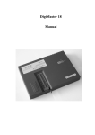
Intro
1.Feature and Function
DigiMaster-III is the third generation multi-functional Automobile data
adjusting equipment developed by Nanning Yanhua Electronics Co.,Ltd. It
bases on a high performance hardware platform which takes high-speed CPLD
and the ARM11 processor as the core device. Seven inch LCD touch-screen
with high resolution makes its interface easy-used. Working with various
types of adapter you can easily achieve odometer correction¡¢Audio
decoding¡¢airbag resetting¡¢engine ECU resetting¡¢IMMO, programming key
for Benz and BMW etc. It is applicative for all types of data processing
such as OBD connection, dashboard soldering, CAS-BDM.
It contains the advanced technology of programming new keys for BMW and
Benz, CAS-BDM reading/writing and resetting, 35080V6 erasure etc. The
operation interface is highly user friendly, large numbers of pictures
and particular description makes your operation pleasant. Online
updating and module authorization keeps you always on the leading edge
of technology.
2.Connector Instruction
1
25 Pin adapter connector
8
15 Pin adapter connector
2
Mini USB Connector
9
Power adapter
3
USB Mouse Connector
10
switch
4
RJ45 LAN Connector
11
Power Indicator Light
5
Earphone Connector
12
Touch-Pen Connector
6
SD Card Connector
13
Keyboard
7
Microphone Connector
14
7 Inch LCD Touch-screen
¡¤°´¼ü¹¦ÄÜ˵Ã÷£º
Keystoke
Function Instruction
F1
Backspace
keyboard
open/close soft-keyboard
ESC
ESC
OK
Enter
The device will become Dormancy with black screen if no operation after XX minutes. Please click the screen to
active it.
3.Adapter List
Product Name
OBP Adapter
ICP Adapter
NEC Adapter
NEC 14-PIN cable
W203/W220 Adapter
TMS370 Programmer
MCU Adapter
K&CAN Adapter
CAN-OBD DMI
VW AUDI OBDII
BENZ 38PIN
BENZ OBD
BMW E36
BMW E36 Meter Socket Connecting Cable
BMW E38/39
BENZ 95S
JAGUAR11DU
C/E CLASS
Ford Ranger
9S12 Adapter
Lexus LS400 Adapter
Grand Cherokee Adapter
W211 Adapter
E65/E66 Adapter
CAN&BDM Programmer
BMW CAN Adapter
MC705-PROG Adapter
MC711-PROG Adapter
NEC KEY
MC705E6
CAS OBD II
NXP
IAR key
ESL
29FXX
Software Instrallation
This section will show you how to install software of DigiMasterIII as well as how to connect it with your PC.
1.Installing D3 Tool
Setp 1: Double-click the installation files in the CD.
Step 2: Choose the route of Installation
Step 3: Open the software interface as below after installation
2.Connect the D3 with PC and internet
Step 1: Connect the D3 USB with PC. Click "Cancel" after the window bombed as below.
Step 2: Click "OK" to close the bombed warning dialog.
Step 3: The below window will appear after successful connecting with device.
Step 4; Just reconnect the USB cable if the USB connecting is cut showed as below window.
Insert the connector of LAN cable into RJ45 LAN connector of D3 to make online update.
3.Remote Assistance
Our engineers will provide you on-line technology support via internet when you choose long-distance
assistance function.
Step 1: Please contact the Sales from my company to obtain an IP before the Remote Assistance. Then connect your D
with internet.
Step 2: Open D3 Tool software to enter"Remote Assistance", then choose "Require Remote Assistance".
Step 3: Input the obtained IP and click "OK" in the bombed window¡£
4.Kernel renovation
Please don't try easily because Kernel Renovation being hazardous. Normally it is used on the useless because o
the lose of kernel.
Step 1; Click keystoke "8" and "OK" together, then power on. The indication of "Press OK to continue and ESC
cancel" will appear on the screen. Press "OK" into Renovation.
Step 2: "Found new hardware" is found in the system when you connect USB cable with the PC.
to
Step 3: Choose " Install software automatically", Click "next".
Step 4: Running D3 tool software, choose "KERNEL update"
Step 5: Indication "USB connect successfully" will appear as below after the USB is connected.
Step 6: Click "KernelUpdate", choose kernel files, then click "OK" to start renovation.
Step 7: Several minutes is need for kernel renovation. It is finished when the indication of "USB connect failed" appear
Easy Operation Manual
Helping you checking accessories£¬ complete the activation£¬ authorization and updating.
1.Activation
Digimaster-III need to be activated on line with the Activation code provided by us in the first using. You can activate a
recharge Digimaster-III by the following steps.
Step 1: Power on and connect the D3 with internet. The unactivated£DD3 show as below. Click "OK" to start activation
Step 2: Input the validation code in the left dialog, Click "next" to download update programme and management
programme.
Step 3: Activation window will appear after downloading Management programme. Please input your information
Step4 Enter the activation code and password provided by sales then click "next".
2.Paymemt
Step 1: Recharge dialog will appear after D3 activation in the first use. If no, click "Payment" in "management
center" to start recharging.
Step 2: Input the Recharging code and password provide by the sales. Click "Next".
Step 3; Click "Finish" to finish the recharging after reminding of successful Payment appear.
3.Upgrade
We provide frequent upgrade of software & hardware programme,new vehicle models or amend hole in order to improve
the functions of Digimaster-III. Please note the upgrade affiche in our website http://www.autoemaster.com/en/
Step 1; Click "Software upgrade" to find new upgrade. Input the Validation code in the dialog to start download and
upgrade.
Step 2; It will remind you whether you need adapter upgrade after software update. Click "YES" to start adapter upgrade;
Click "NO" to next step.( No need to upgrade adapter frequently)
Step 3;
Enter the verify code and click next The D3 will restart automaticlly after software upgrade.
Operation sample
In This section, we use a specific car as an example to elucidate the entire proceeding of odometer
correction?Audio decoding?airbag resetting?Controlling ECU resetting?IMMO, programming key for Benz
and BMW etc.
1.Programmer
1.1 Files Operation
You will find the following interface during many operations( IC programming, CPU programming,Odometer
adjusting,Audio decoding). It show the current data read from the IC by HEX format. You can adjust or save the data in
this interface.
HEX address is in the left column. Data area is in the right column. Data ASCII display is in the bottom when you mov
the scroll bar.
item
function
ReadData
Read data from device
SaveData
Save data file to SD card
WriteData
Write data into device
DackData
Import data to device
ModifyData
shift to modify modle
Close
Exit
item
function
Fill
Fill a section address with data
WriteData
Write data into device
VerifyChip
Verify data to find if WriteData successful
Reflush
Reflush device with all FF
Copy
Copy a slice of data
Paste
Paste data
Undo
Cancel the previous action
Quit
Return to data interface
1.2 IC Programming
Step 1: Connect the chip
De-solder or link the chip to the OBP adapter according to the instruction.
Step 2: Choose the corresponding chip in this interface to begin read or program the chip.
1.3 CPU Programming
Step 1: Connect the chip
De-solder or link the chip to the OBP adapter according to the instruction.
Step 2: Choose the corresponding chip in this interface to begin read or program the chip.
1.4 Signal Generator
Frequency signal generator can generate the specified speed signal, connect to the signal pin in the
odometer and then used to run the odometer.
2.Audio decoding
When the vehicle audio was power off because of buttery damage, the audio will start the anti-theft system automatica
Digimaster III can calculate the audio code out or initialize the it.
2.2 Audio Code Management
Step 1: De-solder the corresponding chip according to the software prompts. Click "Next" to begin decoding.
Step 2: Please remember the code in the pop-up dialogue box, click"Next", the code was written in the chip.
Step 3: Solder the chip back to the board, and then use this new code to decode the audio.
2.3 Address Code
These models only need to short-circuit some welding spot to reset the code, the software will give a specific method
3.Meter System
3.2 IC Adjusting
De-solder the chip from the odometer, and solder it back after adjusted.
To make sure the data was safe, please save the original data before change it by yourself.
Step 1: Click on "Odo adjuster"on the homepage, and then choose the car model of the odometer. For example:
American vehicles- Chrysler.
Step 2: Take Dodge Ram for example, de-solder the memory chip on the odometer board, and solder the chip to the
OBP adapter.
Step 3: Save the data and enter the expected mileage.
Step 4: After it prompted succeed, click on "Exit". Solder the chip back to the odometer.
3.3 ICP Adjusting
Step 1: Take American vehicles- Chrysler- 300K for example: Choose "Program BCM module", solder the
wires to the welding spot of the odometer, then click"Next"
Step 2: Save the data and enter the expected mileage.
Step 3: After it prompted succeed, click on "close". De-solder the wires off the odometer.
3.4 OBD Adjusting
Step 1: Take European Vehicles- VW for example, choose "Diagnosis". In this page it list all the models that
can be adjusted via OBD way, here we choose "Autodetect", it can identify the car model automatically.
Step 2: Check the outfit of the cable, insert the OBD cable to the Diagnosis port, click "Next".
Step 3:
enter the expected mileage.
4.Anti-Theft System
This function can be divided into two parts: Anti-theft code reading(VW, Citroen and Puget) and program keys for BMW and
Mercedes Benz.
Features of some adapters:
Adapter Name
9S12
Feature
Adapter
OBD Adapter
CAN Adapter
CAS-OBD Adapter
4.1 Anti theft Code Reading
Step 1: Click"Anti-theft System" on the Homepage, and choose the vehicle model of the anti-theft device.
Take "VW- AUDI - New Passat" for example.
Step 2: Find the chip on the circuit board according to the instruction(e.g.93C86), remember the chip direction
and solder it off, weld it on the adapter and then click "Next".
Step 3: The anti-theft code will be shown in the dialogue box.
4.2 Key Binding
YH Key Binding:
The BZ-KEY and BM-KEY produced by our company can only be programmed by our key programmer(This key
programmer also support original key programming), therefore, you need to bind the keys to the programmer before
using them.
About "Use the last data"
Suitable for the last data: If you are using Automatic mode, and the operation was stop accidentally, you can use the
recorded data and begin with the last step, do not need to start all over again.
Key Binding Steps:
To download the bond key information to the device key list.
Step 1: Click ""Key Register" in Management Center.
Step 2: Enter the verification code into the pop-up Dialogue box.
Step 3: The device will download update to your key list.
About Automatic mode, Advanced mode and Special mode.
Key programming can be done by Automatic mode and Advanced mode. The results of both methods are the same and
the process is also similar, the only difference is: when in Advanced mode, you can use you own data (bin format or othe
YH format), skip some steps to save time and tokens. Special mode suitable for BMW using two keys in one key chann
4.3 Mercedes Benz Key Programming
Step 1: Go to the Mercedes Benz Key programming page.
Step 2: Take S Class W220 as example, click "S Class", choose Automatic mode, you will see there are 3
steps to program the key for Benz W220.
Step 3: First step, program EIS, choose 05X32/1D69J to enter the following page.
Step 4: De-solder the two CPU according to the diagram, and solder them to the adapters.(to avoid mix
up
please mark the two CPU before taking them off)
Step 5: After read the data it will show the SSID information etc. Choose the key number you want and then
click "Write data" to finish the EIS adjust.
Step 6: step 2, DME. Take 95040 for example, check the picture and remove the chip to the adapter, click
"Next".
Step 7: After read the data, it will show the ECU information, click "Write data" to finish the ECU programming.
Step 8:Step 3, ESL. Check the picture and remove the chip to the adapter, click "Next".
Step 8: click "Write data" to finish this step.
Step 9: Step 4, key programming (this step is based on the data of step 1, if not implemented "Step 1" , this
step can not be operated). Take YH Key for example. Before program the YH Key please make sure it was
registered.
Step 10: Choose the key No. to begin key programming.
4.4 BMW Key Programming
Step 1: Go to the BMW Key programming page.
Step 2: Take "9S12 Adapter - Automatic mode - CAS2 1 Series White shell CAS" for example.
Step 3: Click "Step 1: CAS Reading". After read the data the following interface come up, the red key No. has been used
Choose the Key No. you want and click"Next" to finish the first step.
Step 4: Choose "Step 2: Key programming". Place the key in the slot of the adapter(If the key is YH Key please make
sure it was registered before programming). Click "Next". The pop-up dialogue will show the information of the current
key.
Step 5: Choose the Key No. you want to program, it will pop-up the tokens dialogue box, click "Next" to continue.
Step 6: During the programming process it will prompt you the quantity of the used key and the key can be bond, click
"OK". When the used key has reached to 20, the key storage area was full, you need
update key list, please refer to 7.4 Reading Key List
to go to the management center
Step 7: Connect the 9S12 adapter to Digimaster III, click "Step 3: CAS programming" to write the data back to the CAS
If your BMW key was successfully programmed once, and you want to change to another key No.or another car,
please contact our Technical department.
5.Airbag Resetting System
After airbag detonation,the error record will be saved in the memory code of circuit board by airbag ECU. If
you write the data generated before detonation when the computer hard disk not destroy, then you no need to
change the circuit board.
5.1 Airbag Resetting
Step1: Enter the Airbag Resetting interface, choose the relevant model. Here we take Toyota as example.
Step2: The airbag will be showed in list by number.Take
"Toyota09170-06340" as example, you can find out
the chip in airbag ECU according to the diagram, then dismantle the chip to install to OBP Adapter, click "next
step" to go.
Step3: After finish reading data, it will prompt you whether need to restore airbag. Click "next step", the data
will be restored to airbag chip.
6.Control Computer
6.1 Resetting the Control Computer Data
Step1: Choose car model. Take "Passat B4" for example.
Step2: According to the diagram, dismantle the chip and install to ICP Adapter, click "next step" to go on.
Step3: After finish reading data, it will prompt that "it will cover the engine computer data", then click "next
step" to write data into the engine computer.
Step4: After all these operations, just need to put the chip back to car.
7.Management Center
7.1 Software Update
Click "Update" --- "Software Update"¡£
As for the details of update steps, please refer to "3 Up-guide"
7.2 Adapter Update
Step1: Click "Update"---"Software update"
Step2: In "Usual Adapter" list, there are adapters needed to be updated in Odometer Adjustment and Airbag
Resetting.
Step3: Mark the box of needed adapter, click "Upgrade" button. It will pop-up a box if the interface need to be
converted to upgrade state in upgrading adapter. Please click "Pictures" to check how to convert the switch to
upgrade state.
Click "OK" to start to upgrade adapter.
Tip : Convert to "NXP Adapter" upgrade icon to upgrade the NXP Adapter.
7.3 Key Register
Download and update your YH key List.
As for more operation details, please refer to "Demo"---"IMMO"---"Key Binding System"---"Key Binding".
7.4 Reading Key List
Reading the key ID bound to your device.
It will prompt you upgrade before reading key list, the steps are the same as the software upgrade. If you have done
software update in recent days, please click "No" to skip this step.
7.5 YH Key Information
Read some infor, such as YH Key ID, use condition, etc.
Insert the key to adapter as figure and click " Next", a dialog box will pop up to show you the key infor.
Benz key information
BMW key information
7.6 Authorise
You can buy certain function model to use permanently through authorise card.
Step1: Click "Authorise" and enter validate code, and click "Next" to go on.
Step2: Enter the authorise card number and password which sellers sent you, then click "Next" to complete the
authorise.
7.7 Module Price List
List the authorise module you bought. You also can buy authorise module in this list by yourself.
Step1: It will prompt you upgrade before reading module price list, the steps are the same as the software upgrade.If y
have done software update in recent days, please click "No" to skip this step.
Step2: The module price list will show as follows. You can see the amount of authorise module you chose and the rema
tokens in the lower-left corner. If you just want to see what it looks like when you chose the authorise module, please
"Back" to exit.
Step3: If you want to buy the authorise module, please mark in the box and click "purchase now". A dialog box will pop
and show the module list you chose, then click "Next" to go on.
Step4: System will connect server automatically. Enter validate code and click "Next", you will buy the module
successfully.
7.8 Remote Assistance
Through Internet, our engineer will do remote assistance for your D3 to help you when needed.
Step1: Make sure your D3 has connected to internet.
Step2: Contact with us, we will give you an IP number.
Step3: Click "Ask For Remote Assistance", enter the IP number in the pomp-up box, and "OK".
7.9 Stylus Proofreading
If there are some location deviation when you touch screen, please use this function to do stylus
proofreading.
Appendix
Appendix
Appendix2 Adapter Introduction
Picture
Product Name
Available Model
OBP Adapter
Applicable to EEPROM meter, airbag ECU, audio, ECU
which need to be unsoldered.
ICP Adapter
Applicable to free stitches of 93 series, 25 series, 3508
EEPROM, CPU meter, airbag ECU, audio, ECU, etc.
NEC Adapter
35080 V6
Adapter
NEC 14-PIN cable
Applicable to CPU free switch connecting of NEC serie
For 35080 series IC reading and writing
Use together with NEC Adapter, applicable to CPU free
switch connecting of NEC series.
Applicable to EIS ECU module programming of
Mercedes-Benz C/S class electronic chassis W203/W220.
Available model:
W203/W220 Adapter 1.W 220 EIS(08AZ60/1J35D)EIS(08AS60/4J74Y)
2.W 215 EIS(08AZ60/1J35D)EIS(08AS60/4J74Y)
3.R230 EIS(08AZ60/1J35D)EIS(08AS60/4J74Y)
4.C CLASS W203 EIS(08AZ60/1J35D)
TMS370 Programmer
Applicable to anti-theft reading for old Jetta, audio
decoding for Deco and Opel.
MCU Adapter
Applicable to MCU meter of China model. The MCU ch
can be 12F629, ATMEGA16L, ATMEGA8L, etc.
Applicable to airbag resetting via K-Cable for VW &Audi,
CAS module programming for BMW.
Applicable to the new BMW:
1.CAS2 X5(E70)9S12DG256;
2.CAS2 1 ser white shell 9S12DG256;
3.CAS2 1 ser black shell 9S12DG256;
4.CAS2 3 ser white shell 9S12DG256;
5.CAS2 3 ser black shell 9S12DG256;
K&CAN Adapter
6.CAS2 5 ser white shell 9S12DG256;
7.CAS2 5 ser black shell 9S12DG256;
8.CAS2 6 ser white shell 9S12DG256;
9.CAS2 6 ser black shell 9S12DG256;
10.7 ser (E66)9S12DG256;
11.CAS3 X5(E70)9S12XDP512;
12.CAS3 X6(E71)9S12XDP512;
13.CAS3 1 series 9S12XDP512;
14.CAS3 3 series 9S12XDP512;
15.CAS3 5 series 9S12XDP512;
16.CAS3 6 series 9S12XDP512
CAN-OBD DMI
Applicable to process of some Audi A6L & A8L.
VW AUDI OBDII
Applicable to OBD adjustment for VW, Audi, Benz & BM
BENZ 38PIN
Applicable to free switch adjustment for Benz S Class
(before Year1999)
BENZ OBD
BMW E36
BMW E36 Meter
Socket Connecting
Cable
BMW E38/39
BENZ 95S
JAGUAR11DU
Applicable to free switch adjustment for Benz SLK Clas
(before Year2000)
Applicable to free switch adjustment for BMW E36
Applicable to meter adjustment with socket connect cab
for BMW E36
Applicable to meter adjustment with socket connect cab
for BMW E38/E39
Applicable to meter adjustment with socket connect cab
for Benz S Class, Year1995
Jaguar meter socket connecting cable
C/E CLASS
Ford Ranger
Applicable to meter adjustment with socket connect cab
for Benz C &E Class, Year2000-2005
Applicable to Ford Ranger.
Applicable to CAS ECU module programming for BMW
3/5/7 series of electronic chassis E90/E60/E66 (after
2005), and EIS ECU module programming for
Mercedes-Benz S/E/C class of electronic chassis
W220/W211/W203(after 2005)
Available Model
1.W 220 EIS 912DG128/0K50E ( 9-112)
2.W 220 EIS 912DG128A/3K91D (9-112)
3.W 220 EIS 912DC128A/3K91D (9-112)
4.W 220 EIS 9S12DG128/1L85D (9S80)
5.W 215 EIS 912DG128/0K50E ( 9-112)
6.W 215 EIS 912DG128A/3K91D (9-112)
7.W 215 EIS 912DC128A/3K91D (9-112)
8.W 215 EIS 9S12DG128/1L85D (9S80)
9.R320 EIS 912DG128/0K50E ( 9-112)
10.R320 EIS 912DG128/3K91D ( 9-112)
9S12 Adapter
11.R320 EIS 912DC128A/3K91D (9-112)
12.R320 EIS 9S12DG128/1L85D (9S80)
13.W211 EIS 912DG128/0K50E ( 9-112)
14.W211 EIS 912DG128/3K91D ( 9-112)
15.W211 EIS 912DC128A/3K91D (9-112)
16.W211 EIS 9S12DG128/1L85D (9S80)
17.W209 EIS 912DG128/0K50E ( 9-112)
18.W209 EIS 912DG128/3K91D ( 9-112)
19.W209 EIS 912DC128A/3K91D (9-112)
20.W209 EIS 9S12DG128/1L85D (9S80)
21.W219 EIS 912DG128/0K50E ( 9-112)
22.W219 EIS 912DG128/3K91D ( 9-112)
23.W219 EIS 912DC128A/3K91D (9-112)
24.W219 EIS 9S12DG128/1L85D (9S80)
25.Old BMW EWS4
26.CAS1 7 series 912DG128A(3K91D)9-112
27.CAS1 7 series 912DG128(0K50E)9-112
28.CAS2 X5(E70)9S12DG256
29.CAS2 1 ser white shell 9S12DG256
30.CAS2 1 ser black shell 9S12DG256
31.CAS2 3 ser white shell9S12DG256
32.CAS2 3 ser black shell 9S12DG256
33.CAS2 5 ser white shell 9S12DG256
34.CAS2 5 ser black shell 9S12DG256
35.CAS2 6 ser white shell 9S12DG256
36.CAS2 6 ser black shell 9S12DG256
37.7 series (E66)9S12DG256
Lexus LS400 Adapter
Grand Cherokee
Adapter
W211 Adapter
E65/E66 Adapter
Applicable to odometer IC(457C) of
LexusLS400(1992-1994)
Applicable to odometer CPU of Grand Cherokee
Applicable to process of EIS ECU module for Benz E Clas
W221(2002-2005)
Applicable to process of CAS ECU module for BMW 7
series E65/E66(2002-2004)
Applicable to process of EIS ECU module for BMW 3/5/7
series E90/E60/E66(after 2005)
Available model
CAS-BDM
1.W 220 EIS 9S12DG128/1L85D (9S80)
Programmer
2.W 215 EIS 9S12DG128/1L85D (9S80)
3.R320 EIS 9S12DG128/1L85D (9S80)
4.W 211 EIS 9S12DG128/1L85D (9S80)
5.W 209 EIS 9S12DG128/1L85D (9S80)
6.W 219 EIS 9S12DG128/1L85D (9S80)
BMW CAN Adapter
Applicable to process of CAS ECU module (odometer
socket)for BMW 3/5/7 series E90/E60/E66(after 2005)
1.S Class W 140 DAS IMMO ECU 05X32(0D69J)
2.S Class W 140 DAS IMMO ECU 05X32(0D53J/0D62J
MC705-PROG
Adapter
3.S Class W 220 EIS ignition module 05X32(1D69J)
4.CLK Class W208 EIS ignition module 05X32(1D69J)
5.C Class W202 EIS ignition module 05X32(1D69J)
6.E Class W 210 EIS ignition module 05X32(1D69J)
7.ML Class W163 AAM 05X32(G47V/1D69J )
MC711-PROG
Adapter
NEC KEY
EW S_K
Old BMW EWS2(2D47J,0D46J)/EWS3£¨2D47J,0D46J
Mercedes Benz S, C, E, SL, CL, CLK and CLS Class Ke
adjust EWS through K line
1.MOTOROLA key chip
2.E Class W 210 ESL(05E6/G72A)
3.E Class W 211 ESL(05E6/0F82B)
MC705E6
4.CLK Class W208 ESL(05E6/G72A)
5.CLK Class W209 ESL(05E6/0F82B)
6.CLS Class W219 ESL(05E6/0F82B)
7.C Class W202 ESL(05E6/G72A)
8.C Class W203 ESL(05E6/0F82B)
CAS OBD II
NXP
BMW 7 series E65 before 2006
7936,7941,7942,7943,7944,7946,7947,7952,7961
IAR key
Benz
1.MOTOROLA key chio;
2.E Class W 210 ESL(05E6/G72A);
3.E Class W 211 ESL(05E6/0F82B);
ESL
4.CLK Class W208 ESL(05E6/G72A);
5.CLK Class W209 ESL(05E6/0F82B);
6.CLS Class W219 ESL(05E6/0F82B);
7.C Class W202 ESL(05E6/G72A);
8.C Class W203 ESL(05E6/0F82B);
29FXX
Old Mercedes Benz DME Chip
Appendix3 Replaced Chip List
Original Chip
Replaced Chip
Remark
93C06
93C46
93C06 cannot replace 93C46Ê
9314
93C46
9314 cannot replace 93C46Ê
C46M6
93C46
DD72
93CS66
DD72 cannot replace 93CS66
DD82
93CS66
DD82 cannot replace 93CS66
S220
93CS66
S220 cannot replace 93CS66
93C56
93C66
93C56 cannot replace 93C66
C56M6
93CS66
C56M6 cannot replace 93CS66
CS56
93CS66
CS56 cannot replace 93CS66
85C72
24C16
85C72 cannot replace 24C16
85C82
24C16
85C82 cannot replace 24C16
24C01
24C16
24C01 cannot replace 24C16
24C02
24C16
24C02 cannot replace 24C16
24C04
24C16
24C04 cannot replace 24C16
24C08
24C16
24C08 cannot replace 24C16
D6253
24C16 or 24C01
D6253 cannot replace 24C16
D6254
24C16 or 24C01
PDH001
X2444P or X24C44
PDH004
X2444P or X24C44
X24C01
no
D6254 cannot replace 24C16
X24C01 & 24C01 cannot replaced each other
Appendix4 Chip Dismantling and Soldering
I.Chip Dismantling and Soldering:
1 The choice of iron:
It should be connected with ground safely. When there is no constant temperature soldering iron, the 20W interna
heat-type or 25W external heat-type soldering iron can be OK, but ensure that the former should not exceed 25W, and
the latter does not exceed 30W .
2 The choice of flux:
Rosin is the best choice. Solder paste will never be allowed to use in soldering. You should change the rosin immediate
when it turns to black.
3 The choice of solder wire:
The imported solder wire with low melting point and rosin is the only choice
II.Chip disassembling
1.W hen unsoldering biserial & straight inserted chip, you can clean out the soldering tin on the pin by disordering gun
disordering wire, please don't draw hard.
2.W hen unsoldering patch or chip, melting more rosin on the two rows of pins, and heat them up until the chip loos
completely, then remove it. Please don't pry hard.
3.Please do not heat the chip too long, or it will be damaged.
4.If there is protection paint on the chip, please heat it up with iron, and scratch gently with a blade or tweezers, th
dismantle the chip.
5.How to wipe off the protection paint on the circuit board or IC? Before soldering, please heat the layer of protecti
paint with iron or hot air to 70-80 degrees Celsius, and then peel gently with a word screwdriver.
III.Chip Soldering
1.Please do not heat the chip too long, or it will be damaged.
2.The iron should be wiped with a damp cloth or soaking sponge to keep it clean ,because it won't be easy to disorderi
tin in a state of high-temperature oxidation for a long time.
3.The heat conduction should depend on the tin, and it does no good to soldering by the iron head-to-chip hard.
4.Don't move or shake the chip before the soldering solidified.
5.W hen soldering, you had better first solder the diagonally pins to fasten the chip, and then do other pins.