1
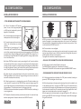
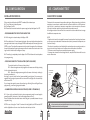
EN
MC102
USER / INSTALLER MANUAL
ON
1
23456789
10
v2.2
REV. 04/2015
00. CONTENT
01. SAFETY INSTRUCTIONS
ÍNDEX
STANDARDS TO FOLLOW
01. SAFETY INSTRUCTIONS
ATTENTION:
STANDARDS TO FOLLOW
1B
02. THE CONTROL BOARD
TECHNICAL SPECIFICATIONS
PROGRAMMING PRE-RECOMENDATIONS
2A
2B
03. DIPPERS
DIPPERS FUNCTION’S BOARD
3A
04. CONFIGURATION
INSTALATION PROBLEM
4A
05. COMPONENT TEST
CAPACITATOR SCHEME
5B
06. TROUBLESHOOTING
FINAL CONSUMERS INSTRUCTIONS
INSTRUCTIONS FOR SPECIALIZED INSTALLERS
6
6
07. WIRING DIAGRAM
CONTROL BOARD COMPONENT CONNECTION
7
2A
EN
• To ensure the safety of people, it is important that you read all the following instructions.Incorrect installation or incorrect use of the product can cause physical injury
and material damage.
• Keep these instructions in a safe place for future reference.
• This product was designed and produced strictly for the use indicated in this manual.
Any other use, not expressly indicated here, could compromise the good condition/operation of the product and/or be a source of danger.
• ELECTROCELOS SA is not responsible for the improper use of the product, or other use
than that for which it was designed.
• ELECTROCELOS SA is not responsible if safety standards were not taken into account
when installing the equipment, or for any deformation that may occur to it.
• ELECTROCELOS SA is not responsible for the safety and proper operation when using
components not sold by them.
• Do not make any modifications to the operator components and / or their accessories.
• Beffore installation unplug the automatism from the source of power.
• The installer must inform the client how to handle the product in case of emergency
and provide this manual to user.
• Keep remote controls away from children, to prevent the automated
system from being activated involuntarily.
• The customer shall not, under any circumstances, attempt to repair or tune the automatism. Must call qualified technician only.
• Connect the automatism to a 230V plug with ground wire.
• Control board for indoor use.
2B
EN
02. THE CONTROL BOARD
02. THE CONTROL BOARD
PROGRAMMING PRE-RECOMMENDATIONS
TECHNICAL SPECIFICATIONS
Before proceeding to the control board configuration, note the following points listed in
the table below in order to better understand the control board function:
110V
230V
• Power supply
AC 110V 50/60Hz
AC 230V 50/60Hz
• Lightbulb’s output
AC110V 40W máx.
AC230V 40W máx.
• Motor’s output
AC110V 750W máx.
AC230V 750W máx.
• Working temperature
AC24V 8W máx.
-20°C a +50°C
• Incorporated Radio Receptor
• OP Transmitters
• Maximum memory capacity
433,92 Mhz
12 bits ou Rolling Code
200 Códigos
M2 connector
• Auxiliary accessories output
M1
10 • Light bulb connection’s output (AC230V 40W máx.)
11 • Light bulb connection’s output - common (AC230V 40W máx.)
12 • Light bulb connection’s output or courtesy light (AC230V 40W máx.)
13 • Motor’s output - Opening
14 • Motor’s output - Common
15 • Motor’s output - Closing
16 • 230V line input (phase)
17 • Not used
18 • 230V line input (neutral)
M3
19 • Antenna mass input
20 • Antenna hot pole input
21 • Place Shunt for motors up to 500kg (included)
22 • Remove Shunt for motors up to 500kg
M1 Connector
M2
01 • Closing limit-swich input signal (NC)
02 • Opening limit-swich input signal (NC)
03 • Open/close transmitter button’s input (NA)
04 • Safety device input - complete direction inversion (NC)
05 • Pedestrian transmitter button’s input (NC)
06 • Safety device input - 2 seconds inversion (NC)
07 • Safety device input common / STARTs
08 • Power supply output for accessories 0V
09 • Power supply output for accessories 24V AC - 8W máx.
M4
• CONNECTOR’S DESCRIPTION
Limit-switches :
01 and 02 • Make sure that the limit switches connections are synchronized
with the FCH and FAP LEDs (see explanation in page 4A at point 3). Test it by
moving the automatism limit-switch’s spring by hand and see if the it lights up
the FCH and FAP LEDs in the correct ways (FCH LED turns off with a closing
signal and the FAP LED turns off with the opening signal).
Safety circuits:
04 • This circuit allows the connection of all types of safety devices such as
photocells, safety bands, etc. This device operates only in the gate closing and
it reverses the automatism’s movement,when activated.
06 • This circuit allows the connection of all types of safety devices such as
photocells, safety bands, etc. This device acts as both the closing and the
opening and it reverses the automatism’s movement for 2 seconds,when
activated.
Light bulb:
10 • This is an intermittent output and must be used lightbulbs that do not
have electrical circuit because the output itself is programmed to create a
flashing effect on the bulb (apply only a lightbulb witg socket and bulb). It does
quick flashes when it is opening, it remains off when paused and it flashes
slowly during closure. If you want that, during the pause time, it remains lit
continuously, read the last paragraph on page 05A.
12 • Output for light bulb or courtesy light, according to what is selected in
Dipper 3 (see p. 3A).
When used in lightbulb mode, it must be equipped with an electrical circuit that
transforms this continuous output in flashing mode. This will only work during
the automatism work time.
When used in courtesy light mode, you should be aware of the light maximum
consumption capacity because the output only supports 40W.
If the consumption is higher, intersperse a power relay.
Capacitator:
13 and 15 • You should connect the capacitator between the outputs 13 and 15.
3A
EN
3B
EN
03. DIPPERS
03. DIPPERS
DIPPERS FUNCTION’S BOARD
DIPPERS FUNCTION’S BOARD
ON
ON
OFF
OFF
1
2
3
4
5
6
7
8
9
10
NOTE: The control board in standard mode has all the dippers in OFF mode.
Dip 4
and
Dip 5
ON (cima)
OFF (baixo)
The SOFT STOP function is triggered
only after the control board receives
the limit switch signal. It continues
the movement for another 3
seconds.
The SOFT STOP function is triggered
3 seconds before the control board
receives the limit-switch signal.
When it receives, it immediately stops
the automatism.
Dip 2
Enables the SOFT START and SOFT
STOP functions.
Disables the SOFT START and SOFT
STOP functions.
Dip 3
Enables the lightbulb and courtesy
light output (M1 - terminal 11 and
12). Only during the motor’s work
time.
Enables courtesy light output (M1 terminal 11 and 12) during the work
time, pause time and an additional 3
minutes after closing.
4 5 Dip 4 OFF | Dip 5 OFF
4 5 Dip 4 ON | Dip 5 ON
Step-by-step function with selfclosing.
• During the opening accepts
transmitter signals.
• When the gate stops, does the
timing and automatically closes.
• If it receives a transmitter signal
during closing, it reverses.
• In pause time, it anticipates the
closing.
Step-by-step function with selfclosing, if the gate is stopped at the
limit-switch’s end.
• If the gate is stopped by a
transmitter signal during the opening
and closing course, it will be stopped
until new order.
Dip 1
Dip 4
4A
EN
Dip 6
Dip 7
Dip 8
4 5 Dip 4 OFF | Dip 5 ON
4 5 Dip 4 ON | Dip 5 OFF
Normal Step-by-step function
without automatic closure.
Gate opens or closes only if it
receives transmitter signals.
The behavior will be open-stopclose-stop-open...
Condominium function with
automatic locking:
Transmitters aren’t accepted during
opening and during closing it reverses
direction and stops only at the end of
the course.
Transmitters are not accepted during
the pause time.
Disables the reading of the opening Enables the reading of the opening
limit-switch.
limit-switch.
NOTE: The 6 and 7 dippers avoid shunt placement, when the control board
is applied in engines, which don’t use limit-switches.
Disables the reading of the closing
limit-switch.
Enables the reading of the closing
limit-switch.
Disables the M2/04 safety device’s
reading.
Enables the M2/04 safety device’s
reading.
NOTE: The dipper 8 avoids shunt placement, when the control board is
applied in engines which don’t use safety devices connected to 04 terminal
of M2 connector.
Programming the work and pause
time.
Dip 9
NOTE: The dipper 9 should only be used to trigger the work and pause time
configuration function. When the programming is complete, put it in OFF
mode.
Dip 10 Enables anti-crushing function.
4B
EN
Normal functioning.
Disables anti-crushing function.
04. CONFIGURATION
04. CONFIGURATION
INSTALLATION PROCESS
INSTALLATION PROCESS
• TOTAL OPENING AND TRANSMITTER PROGRAMMING
01 • Place all the dippers in OFF position
(down). In case of not using safety device
at 4/M2 terminal (ex:photocells), place the
dipper 8 in ON to disable it.
4
1
1
2
2
3
4
3
Limit-switches
spring
02
02 • Unlock the engine, place the gate in the
middle position and re-lock the engine.
03 • Connect the power to the control board
check if the limit-switches are activated
correctly.
When wiring the limit-switches at 01 and
01
02 terminals, the FCH and FAP LEDs will remain lit. When moving the spring manually towards closing position, the FCH LED must
turn off and when moving it towards opening position, the FAP LED must go off too. If
the LEDs are turning off switched (FCH for opening and FAP for closing), swap the wires
from 01 and 02 terminals.
04 • Make a START with a help of a wire by connecting the 3 and 7 terminals with the
wire tips and check if the motor is running in the correct direction. When the gate starts
moving to one side, move the limit-switches spring towards the gate’s movement direction and it should stop. If it doesn’t, pull it the other way and it will stop. Swap the motor
wires (13 and 15 terminals from M1 connector) to put in the right direction.
05 • When the gate is synchronized with the limit-switch correct direction, make a
START again between 3 and 7 terminals. The gate will begin to move to one side. Let it
reaches the closed position electrically.
06 • When the gate comes to a closed position, press the P1 button located on the
control board for 2 seconds until the CODE LED (see connection diagram page 07.A)
stays lit. Right away, press the transmitter button you want to be the total opening key
(choose between 1, 3 and 4 buttons shown in the images at the right).
NOTE: When the transmitter button is pressed, the CODE LED must blink, indicating it
is receiving the code.
07 • Release the first button and then press the button number 2 to memorize the pedestrian opening button. Release it and wait for the CODE LED turns off.
5A
EN
03
NOTE: If you select a button other than the nº 2 for pedestrian opening, the control
board will recognize it as complete opening button, which means it will override the
first pressed button. If the pedestrian opening is not wished, do not press the nº2 button and wait for the CODE LED to turn off.
08 • The transmitter is now configured.
NOTE: After setting up a transmitter type, the control board will only accept transmitters from the same type, it means, if the first transmitter is Rolling Code, they must all
be Rolling Code for the central to accept them.
To program other transmitters, repeat the steps from nº6.
• ERASE ALL THE TRANSMITTERS FROM THE CONTROL BOARD
01 • With the gate closed, hold the P1 button continuously.
The CODE LED lights up and wait for 15 seconds until it turns off.
Release the P1 and the LED will flash twice that signals the MEMORY RESET sucess.
• PROGRAMMING THE WORKING TIME AND ENGINE’S PAUSE
01 • With the gate closed, place the dipper 9 to "ON", press transmitter (already programmed) / START and the gate will start to open.
02 • When the gate stops at the open position (opening limit-switch is enabled), wait
for the desired pause time (*) and give a new START to close. This waited time represents the time that the engine will wait between the end of the opening maneuver and
the the automatic closure’s start. This automatic closure will only happen if the 4 and 5
dippers are in the selected positions to activate it (see page 03).
When the gate reaches the closed position, change the Dipper 9 to OFF to finish programming and CODE LED will blink and go off. If the dipper is leaved ON, the programming won’t be finalized.
5B
EN
04. CONFIGURATION
05. COMPONENT TEST
INSTALLATION PROCESS
CAPACITATOR SCHEME
If the control board blocks and a RESET is needed, follow these steps:
01 • Turn off the control board’s power.
02 • Put Dipper 9 to ON.
03 • Reconnect the control board to the power supply and put the dipper 9 to OFF.
To detect which components have problems during an sliding automatism installation,
sometimes is necessary to conduct tests with a direct connection to a 230V power supply. For this, is necessary to interpose a capacitator on the connection to the motor
can work (check the capacitor type to be used in the product manual).
In the diagram below is shown how this connection must be made and how to merge
the different component wires.
• PROGRAMMING THE PEDESTRIAN WORK TIME
01 • With the gate in closed mode put the Dipper 9 ON.
02 • Press the button nº2 to start opening the gate. Upon reaching the desired position,
press again the button to stop the engine. Wait the desired pause time and give a new
START to close. This waited time represents the time that the engine will wait between
the end of the pedonal’s opening maneuver and the the automatic closure’s start. Nearing the limit-switch’s end, the engine will stop.
03 • The setting is completed, place the dipper 9 in OFF to finalize and close the pedestrian programming.
NOTE:
• To perform the tests its not needed to remove the automatism from the place, because this way you can understand if the automatism, directly connected to the power, can
function correctly.
• The order of capacitator wires linked with the automatism wires are not important, as
long as the wires stay linked, one to the Brown wire and the other to the Black.
• The common must always be connected to the power supply.
• To reverse the automatism functioning direction, swap the Black wire with the automatism Brown wire.
• FORCE AND SENSITIVITY REGULATION (ANTI-CRUSHING)
The control board has 2 trimmers (rotary knobs):
RV1 - Allows the engine sensitivity regulation (increases sensitivity by rotating
it in the clockwise direction);
RV2 - Allows the engine power regulation (increases the force by rotating in
the clockwise direction );
Warning: To use anti-crush function (recommended for small gates), it is necessary to
regulate first the engine’s power with the trimmer RV2 and right after the sensitivity
with trimmer RV1.
If you change the engine’s power after performing a Working Time and Engine Pause
programming , a new one is going to be needed.
AUTOMATISM
FOR SLIDING
GATES
Common(Blue)
230V POWER
SUPPLY
Black
Brown
• ILUMINATED LIGHTBULB IN PAUSE TIME (10 AND 11 TERMINALS)
01 • If you wish to activate this function, when programming work time and engine’s
pause (page 04.B), at the point 2, do the following operation from (*).
•Press the pedestrian transmitter button while the gate is paused, between the opening and closing.
Ground wire
04
All tests must be performed by skilled technicians due to serious danger associated with the misuse of electrical systems!
NOTE: In case of using the 11 and 12 terminals for the lightbulb, the DIP3 must be OFF
and the Lightbulb must have a circuit board to make the lamp to blink.
6A
EN
CAPACITATOR
6B
EN
06. TROUBLESHOOTING
SPECIALIZED TECHNICIANS INSTRUCTIONS
FINAL CONSUMERS INSTRUCTIONS
Anomaly
Procedure
Behavior
Procedure II
Discovering the origin of the problem
• Door doesn't •Make sure you have
work
230V power supply
connected to control
board and if it is
working properly.
• Still not working
• Consult a qualified MOTORLINE technician.
1 • Open control board and check
if it has 230V power supply;
2 • Check input fuses;
• Motor
doesn’t move
but makes
noise
• Encountered
problems?
• Consult an experienced
gate expert.
1 • Check all motion axis and associated motion systems related with the motor and the gate to find out what is the problem.
• The gate moves
easily?
• Consult a qualified MOTORLINE technician.
1 • Check capacitors, testing
operator with new capacitors;
• Unlock motor and
move the gate by hand
to check for mechanical problems on the
movement
2 • If capacitors are not the
problem, disconnect motors from
3 • Disconnect the motor from
control board and test them by
connecting directly to power
supply in order to find out if they
have problems
(see page 11.A).
4 • If the motor works, the
problem is on the control board.
Pull it out and send it to our
MOTORLINE technical services
for diagnosis;
5 • If the motor doesn’t work,
remove them from installation
site and send to our MOTORLINE
technical services for diagnosis.
control board and test them
by connecting directly to power
supply in order to find out if they
have problems (see page 09.A);
3 • If the motors work, the
problem is from control board.
Pull it out and send it to our
MOTORLINE technical services
for diagnosis;
4 • If the motors doesn’t work,
remove them from installation
site and send to our MOTORLINE
technical services for diagnosis.
A) SECURITY SYSTEMS::
defective, follow the same steps
until you find all the problems.
NOTE:
In case procedures described in
sections A) and B) don’t result,
remove control board and send
to our technical services for
diagnosis.
• Motor opens • Unlock motor
• Gate opened but
but doesn’t
and move the gate
didn’t close again.
close
by hand to closed
position.
Lock motor again and
turn off power supply
for 5 seconds. Reconnect it and send order
to open
gate using transmitter.
1 • Check if there is any
obstacle in front of the
photocells;
2 • Check if any of the control
devices (key selector, push
button, video intercom, etc.)
of the gate are jammed and
sending permanent signal to
control unit;
3 • Consult a qualified MOTORLINE technician.
All MOTORLINE control boards
have LEDs that easily allow to
conclude which devices are with
anomalies.
All safety devices LEDs (DS) in
normal situations remain On.
All "START" circuits LEDs in
normal situations remain Off.
• Gate doesn’t • Unlock motor and
• Encountered
make comple- move gate by hand to problems?
te route
check for mechanical
problems on the gate. • The gate moves
easily?
• Consult an experienced
gate expert.
1 • Check all motion axis and associated motion systems related with the gate to find out what is the problem.
• Consult a qualified MOTORLINE technician.
1 • Check capacitors, testing
with new capacitors;
2 • If capacitors are not the
problem, disconnect motor
from control board and test it
by connecting directly to power
supply in order to find out if it is
broken;
3 • If the motor doesn’t work,
remove it from installation site
and send to our MOTORLINE
technical services for diagnosis.
If LEDs devices are not all On,
there is some security systems
malfunction (photocells, safety
edges), etc.
If "START" circuits LEDs are
turn On, there is a control device
sending permanent signal.
1 • Close with a shunt all safety
systems on the control board
(check manual of the control
board in question).
If the automated system starts
working normally check for the
problematic device.
2 • Remove one shunt at a time
until you find the malfunction
device .
3 • Replace it for a functional
device and check if the motor
works correctly with all the other
devices. If you find another one
4 • If motor work well and move
gate at full force during the
entire course, the problem is
from controller. Set force using
trimmer on the board. Make a
new working time programming
, giving suffient time for opening
and closing with appropriate
force (page 08.B).
5 • If this doesn’t work, remove
control unit and send it to
B) SISTEMAS DE START:
1 • Disconnect all wires from
START terminal
input (terminal 3 of CN3
connector).
2 • If the LED turned Off, try
reconnecting one device at a
time until you find the defective
device.
MOTORLINE technical services
services.
NOTE: Setting force of the
controller should be sufficient
to make the gate open and close
without stopping, but should
stop and invert with a little effort
from a person.
In case of safety systems failure,
the gate shall never cause
physical damaged to obstacles
(vehicles, people, etc.).
7
EN
2
112
FAP
3
778 8
0
991 10
PED
PULL DS PULL BS
556 6
Connector M2
4 5 6 7
334 4
LED'S
2
LED CODE
START / OPEN
(or)
START /
PEDESTRIAN
PED
FCH FAP PULL DS PULL BS COM
1
FCH
OFF
OFF
ON
ON
SW1
19 20
Connector M3
8
~
24V
9
P1
M4
Receiver
F1
F5A
250V
LAMP
CORT
~~
DV 12/24V
~~
NC
230V
DV 12/24V COM
MOTOR
230V
AP COM CH (P)
0V
(N)
Connector M1
10 11 12 13 14 15 16 17 18
F2
F360mA
250V
RV2
RV1
07. WIRING DIAGRAM
CONTROL BOARD COMPONENT CONNECTION
05
8
EN