1
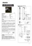
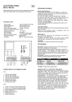
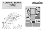
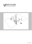
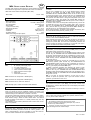
GB
MR4 SINGLE-CHANNEL RECEIVER
PROGRAMMING RADIO-CONTROLS AND/OR TRANSPONDERS
The programming of radio-controls and/or transponders is self-learning,
as follows.
Use the UP or DOWN keys to go to the desired memory position
(viewed on the display from 001 to 500), paying attention to the
TRANSMITTER and TRANSPONDER LEDS, as one of them turning
on means the location is busy. Press the SEL key, the TRANSMITTER
and TRANSPONDER LEDS will begin to flash, and meanwhile send
the code with the radio-control or bring the transponder closer to the
“ML3” proximity reader, (the display will indicate STO stored), the
TRANSMITTER or TRANSPONDER LED will go from off to on and programming is thus complete.
To delete a radio-control or transponder stored previously, use the UP
or DOWN keys to go to the memory location that is busy, press the
SEL key, the TRANSMITTER or TRANSPONDER LED will begin to
flash; press the SET key (the display will indicate "DEL" deleted), the
LED will go from on to off and delete is thus complete.
During normal operation, the display panel indicates the memory location of the device stored previously currently in use.
The MR4 radio receiver is designed for the remote operation of electrical and electronic equipment in conjunction with one or more MOTORLINE radio-controls and/or transponders (MB1, MB2).
- Mod. MR4 :
433,92 MHz
TECHNICAL DATA
- Power supply:
- Max consumption:
- Op. radio-controls:
- Op. transponders:
- Stored codes:
- 1 (one) command relay:
- Working temperature:
- Dimensions:
- Container:
- Protection degree:
- Radio-control range in open spaces:
12-24VAC-DC
4.5 W
12-18 Bit or Rolling Code
Card or Key-ring
500 Max
30VDC 1A
-10°C ÷ 55°C
110x121x47 mm
ABS (UL94V-0)
IP54
30-70 metres
RAPID PROGRAMMING OF RADIO-CONTROLS AND/OR TRANSPONDERS
The rapid programming of radio-controls and/or transponders is only allowed when all the receiver memory is free. To make sure that all the
memory is free, follow the Reset procedure.
Rapid programming means you do not have to select a new memory
location for another radio-control and/or transponder every time, but
starting from position 001, the control unit automatically increases the
memory location and remains on standby for 10 seconds, from the input of a new radio-control and/or transponder to store.
PASSWORD
Once you have finished programming the radio-controls and/or
transponders, you can store a password in the PAS position, to disable
and enable receiver programming, as follows.
Use the UP or DOWN keys to go to the PAS memory position, press
the SEL key, the TRANSMITTER and TRANSPONDER LEDS will begin to flash, and meanwhile use the UP or DOWN key to select a number between 001 and 500, press the SET key, (the display will indicate
"CLO" closed), and the TRANSMITTER and TRANSPONDER LEDS
will go from off to on.
To re-enable programming, use the UP or DOWN keys to go to the
PAS memory position, press the SEL key, the TRANSMITTER and
TRANSPONDER LEDS will begin to flash, meanwhile use the UP or
DOWN keys to select the key number selected previously, press the
SET key, (the display will indicate OPE open).
To delete a password (operation only allowed if the system is open
OPE), use the UP or DOWN keys to go to the PAS memory position,
press the SEL key, the TRANSMITTER and TRANSPONDER LEDS
will begin to flash and meanwhile press the SET key (the display will indicate DEL deleted), the TRANSMITTER and TRANSPONDER LEDS
will go from on to off.
N.B.: if you enter an incorrect password, you will have to wait 5
minutes to repeat the operation, and if you enter another incorrect
password, you will have to wait 1 hour.
CONNECTION OF TERMINAL BOARDS
CN1:
1
2
3
4
5
6
7
: 24 VAC/DC power supply input.
: 0 V power supply input.
: 12 VAC/DC power supply input.
: Clean command contact output.
: Clean command contact output.
: Earth input.
: Antenna hot pole input.
CN2: Connection for Transponder 1 Reader (ML3 ).
CN3: Connection for Transponder 2 Reader (ML3 ).
RESET
CN4: Connection for PC “SW 2189” interface.
If it is appropriate for the factory configuration to be restored (operation
only allowed if the system is open OPE), press the SEL and SET keys
simultaneously, and the LEDS will turn off, and the display will indicate
the PAS position.
N.B.: the display is turned off after one minute of inactivity to save energy.
CN5: Normally open or closed command contact selection.
RECEIVER INSTALLATION
For the optimal operation between transmitter and receiver, we recommend you choose the point of installation carefully. The range is not
merely linked to the technical features of the device itself, but it actually
varies according to the radioelectric conditions of the area.
The receiver is fitted with an antenna consisting of a rigid wire section.
Should you wish to increase the device sensitivity, you can connect a
tuned antenna using a RG58 50 OHM coaxial cable. The antenna
should be placed on the exterior in a visible position away from any
metallic structures.
The installation of two receivers placed less than 5 metres from one another is not possible.
FURTHER FUNCTIONS VIA PC CONNECTION
The receiver can be connected to a Personal Computer through the
use of a “SW 2189” package supplied as an optional, thanks to which
you may access further functions.
FOR THE INSTALLER - IMPORTANT
− All operations requiring the opening of the casing
(such as installation, programming and repair, etc.) must be
carried out by skilled staff only.
− The fixing of power supply leads and connection cables must be
secured through the use of cable clamps.
OPERATION WITH RADIO-CONTROLS AND/OR TRANSPONDERS
The receiver can be combined with MOTORLINE radio-controls and/or
transponders and is designed to store up to 500 different users. We
therefore recommend you make a note of the “memory position - user
name” correspondence in the form provided. For use with radio-controls, the receiver is fitted with an incorporated receiver.
1
Rev. 1.2 03/07
STATEUROP hereby declares that the product below:
MR4 Single-channel Receiver complies with the requirements of Directive R&TTE 99/5/EC.
1
Rev. 1.2 03/07