1
Distributed Power System
SD3000/SF3000
Parallel Gate Amplifier System
Instruction Manual S-3045-2
Throughout this manual, the following notes are used to alert you to safety considerations:
!
ATTENTION: Identifies information about practices or circumstances that can lead to personal
injury or death, property damage, or economic loss.
Important: Identifies information that is critical for successful application and understanding of the product.
!
ATTENTION: Only qualified electrical personnel familiar with the construction and operation of
this equipment and the hazards involved should install, adjust, operate, or service this equipment.
Read and understand this manual and other applicable manuals in their entirety before
proceeding. Failure to observe this precaution could result in severe bodily inury or loss of life.
ATTENTION: The user must provide an external, hardwired emergency stop circuit outside of the
drive circuitry. This circuit must disable the system in case of improper operation. Uncontrolled
machine operation may result if this procedure is not followed. Failure to observe this precaution
could result in bodily injury.
ATTENTION: Inserting or removing a module or its connecting cables may result in unexpected
machine motion. Turn off power to the rack before inserting or removing a module or its connecting
cables.
ATTENTION: The user is responsible for conforming with all applicable local, national, and
international codes.
ATTENTION: The modules in the Parallel Gate Amplifier rack contain static-sensitive components.
Do not touch the modules’ circuit boards or the connectors on the backs of the modules. When
not in the rack, modules should be stored in anti-static bags.
The information in this user’s manual is subject to change without notice.
Reliance™ and AutoMax™ are trademarks of Rockwell Automation.
©1997 Rockwell International Corporation
CONTENTS
Chapter 1
Introduction
1.1 Standard Features ........................................................................................... 1-2
1.2 Related Hardware and Software ..................................................................... 1-2
1.3 Related Publications ........................................................................................ 1-4
Chapter 2
About the PGA Rack
2.1 PGA Rack Mechanical Description.................................................................. 2-1
2.2 PGA Rack Electrical Description ..................................................................... 2-1
Chapter 3
About the PGA Power Supply Module
3.1 PGA Power Supply Module Mechanical Description ....................................... 3-1
3.2 PGA Power Supply Module Electrical Description .......................................... 3-2
Chapter 4
About the PGA Module
4.1 PGA Module Mechanical Description .............................................................. 4-1
4.2 PGA Module Electrical Description.................................................................. 4-1
Chapter 5
Installation Guidelines
5.1 Wiring the PGA Rack....................................................................................... 5-1
5.2 Installing the PGA Rack................................................................................... 5-2
5.3 Grounding Considerations ............................................................................... 5-5
5.4 Module Installation/Replacement Guidelines .................................................. 5-6
5.5 Installing the PGA Power Supply Module ........................................................ 5-6
5.5.1 Connecting AC Input Power .................................................................. 5-7
5.5.2 Installing an Optional External Supply Greater Than +28 VDC ............ 5-7
5.5.3 Connecting the PMI DC Power Technology Module to the PGA Power
Supply Module ...................................................................................... 5-7
5.6 Connecting the PGA Module to the Gate Coupling Circuits ............................ 5-8
Table of Contents
I
Appendix A Rack Specifications.................................................................................................. A-1
Appendix B Power Supply Module Specifications ....................................................................... B-1
Appendix C PGA Module Specifications...................................................................................... C-1
Appendix D PGA Maximum System Power Requirements ......................................................... D-1
Appendix E External PGA Power Supply Interface ..................................................................... E-1
Appendix F Replacement Parts................................................................................................... F-1
II
Parallel Gate Amplifier
List of Figures
Figure 1.1 – Four-Slot PGA Rack and Modules (Part No. 805401-7T) .................... 1-5
Figure 1.2 – Eight-Slot PGA Rack and Modules (Part No. 805401-9CC)................. 1-6
Figure 1.3 – PGA Parallel Motoring and Regenerating System Example ................ 1-7
Figure 3.1 – Power Supply Module Component Layout ........................................... 3-3
Figure 3.2 – Power Supply Module Functional Block Diagram................................. 3-4
Figure 4.1 – PGA Gate Driver Circuitry .................................................................... 4-3
Figure 4.2 – PGA Module Functional Block Diagram ............................................... 4-4
Figure 5.1 – Four-Slot PGA Rack Mounting Dimensions ......................................... 5-3
Figure 5.2 – Eight-Solt PGA Rack Mounting Dimensions......................................... 5-4
Figure 5.3 – Location of Power Supply Ground Terminal and
Four-Slot Rack Grounding Lug............................................................. 5-5
Figure 5.4 – Location of Power Supply Ground Terminal
and Eight-Slot Rack Grounding Lug ..................................................... 5-5
Figure 5.5 – Gate Driver Plug for Cable Assemblies 612436 and 612567 ............... 5-9
Figure 5.6 – PGA System Hardware Connections ................................................. 5-10
Table of Contents
III
IV
Parallel Gate Amplifier
List of Tables
Table 1.1 – Parallel Gate Amplifier System Configurations ......................................1-3
Table 1.2 – DPS Documentation...............................................................................1-4
Table 5.1 – Input Power Connections .......................................................................5-7
Table 5.2 – Connection Sequence for Cable Assemblies 612436 and 612567........5-9
V
Parallel Gate Amplifier
VI
Parallel Gate Amplifier
CHAPTER 1
Introduction
The Parallel Gate Amplifier (PGA) system is used to amplify and distribute the gate
pulse signals produced by the AutoMax™ Distributed Power System's DC Power
Technology module. It can be used with multiple Reliance Power Modules or with
certain other vendor Power Modules. Please contact Reliance regarding the suitability
of other vendor Power Modules for use with the PGA system.
The system is comprised of three major components: the PGA Rack/Backplane, the
Power Supply module, and the PGA modules.
The Power Supply and PGA modules reside in a modular rack of either four slots or
eight slots. The four-slot rack holds the Power Supply and one or two PGA modules
(figure 1.1). The eight-slot rack holds the Power Supply and one to six PGA modules
(figure 1.2). Two channels (A and B) are provided for gate signals on the rack's
backplane. Channel A is used for forward gate signals and channel B for reverse gate
signals.
To connect to the two channels, two types of PGA modules are used. The Output-A
PGA module is used to access the signals from channel A. The Output-B PGA module
is used to access the signals from channel B. The two types of modules are not
interchangeable, but may be combined in the rack as needed to meet the
requirements of the application.
The amplified PGA output signals drive the gate coupling circuits in the DC Power
Modules. Each PGA module can simultaneously drive four six-thyristor power bridges
in one direction, either forward or reverse. With the maximum of six PGA modules
used in the system, a total of 24 power bridges (6 x 4) can be driven.
The PGA's standard DC bus voltage is +28 VDC, but the PGA module is capable of
handling DC bus voltages up to +100 VDC, if required by the application. Voltages
greater than the standard +28 VDC must be provided by an externally mounted power
supply, as described in chapter 3.
The available PGA configurations are listed in table 1.1. A two card PGA parallel
motoring and regenerating system example is shown in figure 1.3.
Introduction
1-1
1.1
Standard Features
The PGA system has the following features:
• Connects to DPS DC Power Technology module
• Capable of driving up to 24 six-thyristor power bridges in parallel (144 gate coupling
circuits)
• Overcurrent protection provided by PCB fuses
• Overtemperature detection by NC faceplate contacts on Power Supply module
• Optical isolation of gate signals from biasing networks and firing circuits
• Physical isolation of gate signals from Power Supply and other circuitry
• Externally mounted 100 VDC power supply option
• UR/CUR Recognized
1.2
Related Hardware and Software
The following related DPS components are available separately:
• AutoMax Universal Drive Controller
• Power Module Interface rack and modules
• Fiber-Optic Cables
• AutoMax Programming Executive software
1-2
Parallel Gate Amplifier
Table 1.1 – Parallel Gate Amplifier System Configurations
Reliance Part No.
Introduction
Description
805401-7R
4-Slot PGA Rack, w/Fan, Power Supply, Output-A
805401-7S
4-Slot PGA Rack, w/Fan, Power Supply, Output-A/A
805401-7T
4-Slot PGA Rack, w/Fan, Power Supply, Output-A/B
805401-9AX
8-Slot PGA Rack, w/Fan, Power Supply, Output-A
805401-9BX
8-Slot PGA Rack, w/Fan, Power Supply, Output-A/A
805401-9CX
8-Slot PGA Rack, w/Fan, Power Supply, Output-A/A/A
805401-9DX
8-Slot PGA Rack, w/Fan, Power Supply, Output-A/A/A/A
805401-9EX
8-Slot PGA Rack, w/Fan, Power Supply, Output-A/A/A/A/A
805401-9FX
8-Slot PGA Rack, w/Fan, Power Supply, Output-A/A/A/A/A/A
805401-9AA
8-Slot PGA Rack, w/Fan, Power Supply, Output-A/B
805401-9BA
8-Slot PGA Rack, w/Fan, Power Supply, Output-A/A/B
805401-9CA
8-Slot PGA Rack, w/Fan, Power Supply, Output-A/A/A/B
805401-9DA
8-Slot PGA Rack, w/Fan, Power Supply, Output-A/A/A/A/B
805401-9EA
8-Slot PGA Rack, w/Fan, Power Supply, Output-A/A/A/A/A/B
805401-9AB
8-Slot PGA Rack, w/Fan, Power Supply, Output-A/B/B
805401-9BB
8-Slot PGA Rack, w/Fan, Power Supply, Output-A/A/B/B
805401-9CB
8-Slot PGA Rack, w/Fan, Power Supply, Output-A/A/A/B/B
805401-9DB
8-Slot PGA Rack, w/Fan, Power Supply, Output-A/A/A/A/B/B
805401-9AC
8-Slot PGA Rack, w/Fan, Power Supply, Output-A/B/B/B
805401-9BC
8-Slot PGA Rack, w/Fan, Power Supply, Output-A/A/B/B/B
805401-9CC
8-Slot PGA Rack, w/Fan, Power Supply, Output-A/A/A/B/B/B
805401-9AD
8-Slot PGA Rack, w/Fan, Power Supply, Output-A/B/B/B
805401-9BD
8-Slot PGA Rack, w/Fan, Power Supply, Output-A/A/B/B/B/B
805401-9AE
8-Slot PGA Rack, w/Fan, Power Supply, Output-A/B/B/B/B/B
1-3
1.3
Related Publications
This manual provides a description of each component of the Parallel Gate Amplifier
system as well as installation guidelines. Note that this instruction manual does not
describe specific applications of the standard hardware.
Additional information about using the Parallel Gate Amplifier as part of an AutoMax
Distributed Power System is found in the instruction manuals, prints, and other
documents shipped with each drive system. Always consult the prints shipped with the
drive system for specific mounting and connecting information about your drive.
The other instruction manuals located in binder S-3000, Distributed Power System DC
Drive, are listed in table 1.2. It is assumed that the user is familiar with these other
manuals in S-3000 before using the PGA system.
Table 1.2 – DPS Documentation
Document Part Number
Document
SD/SF3000 Binder S-3000
DPS Overview
S-3005
UDC Module
S-3007
Fiber-Optic Cabling
S-3009
Configuration and Programming
S-3006 (for SD3000)
S-3036 (for SF3000)
Power Module Interface Rack and Modules
S-3008
Diagnostics, Troubleshooting, and Startup Guidelines
S-3011
Information Guide
S-3012
1-4
Parallel Gate Amplifier
Figure 1.1 – Four-Slot PGA Rack and Modules (Part No. 805401-7T)
Introduction
1-5
Figure 1.2 – Eight-Slot PGA Rack and Modules (Part No. 805401-9CC)
1-6
Parallel Gate Amplifier
Figure 1.3 – PGA Parallel Motoring and Regenerating System Example
Introduction
1-7
1-8
Parallel Gate Amplifier
CHAPTER 2
About the PGA Rack
The PGA rack provides the mechanical means for mounting the Power Supply module
and the PGA modules. The following sections provide mechanical and electrical
descriptions of the rack.
2.1
PGA Rack Mechanical Description
The PGA rack consists of a sheet metal card-cage type enclosure and a backplane.
The backplane contains a proprietary parallel bus with DIN-style connectors in each
slot for the modules. The leftmost slot is provided for the Power Supply module. The
remaining slots are provided for the PGA modules.
The four-slot version of the rack (see figure 5.1) has three identical 48-pin backplane
connectors: one for the Power Supply module and two for PGA modules. The
eight-slot version (see figure 5.2) has seven identical 48-pin backplane connectors:
one for the Power Supply module and six for PGA modules. The Power Supply
connector in each rack is vertically offset so that the Power Supply and PGA modules
cannot accidentally be interchanged.
The PGA rack must be installed within 18.3 m (60 ft) of the drive’s DC Power Module
to ensure the integrity of the Power Module interface signals. The rack is designed to
be panel-mounted. Mounting holes are provided on the flanges that extend above and
below the rack. A grounding lug is provided on the bottom mounting flange. The rack’s
fan assembly is mounted on the bottom of the rack. Rack installation is described in
chapter 5. Rack specifications are given in Appendix A.
2.2
PGA Rack Electrical Description
The four-slot and eight-slot versions of the rack backplane differ only in the number of
PGA modules they support. The backplane provides power and ground, and two
identical channels ("A" and "B") for gate signals. Six gate signals run on channel A
and six on channel B. Each of the gate signals has an associated common signal. The
connection between the DC Power Technology module and the PGA Power Supply
module determines whether the channel carries the forward or reverse gate signals
(see section 3.2).
The gate signals run to the top portion of each 48 pin connector. Four power and
ground signals, +5V, DCBUS, +5VCOM, and DCCOM, run to the bottom. The power
signals reside on the inside layers of the backplane’s four-layer printed circuit board.
The inner power plane shares both the +5V and DCBUS signals. The inner ground
plane shares the two commons, +5VCOM and DCCOM. A noise filter connects
DCCOM to earth ground.
About the PGA Rack
2-1
2-2
Parallel Gate Amplifier
CHAPTER 3
About the PGA Power Supply
Module
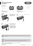
Through its faceplate connectors, the PGA Power Supply module (B/M O-60055)
provides the interface with the DC Power Technology module in the PMI rack. The
Power Supply module provides the gate signals and the DC voltages necessary for
the proper operation of the PGA modules through the backplane of the PGA rack.
The following sections provide mechanical and electrical descriptions of the Power
Supply module. Component layout is shown in figure 3.1. A functional block diagram
is shown in figure 3.2.
3.1
PGA Power Supply Module Mechanical Description
!
ATTENTION: This equipment must be connected to a power source for
which it was designed. Verify that the available power is 115 volts AC
(10 KVA maximum input source).
The PGA Power Supply module plugs into the leftmost slot of the PGA rack. The
module consists of an internal regulated power supply, a printed circuit board
containing a DC-to-DC converter, and a faceplate. The faceplate has two
thumbscrews at the top and two at the bottom to secure the module in the rack. The
back of the module connects to the rack backplane. Power Supply module
specifications are given in Appendix B.
The faceplate of the module contains a green LED indicator, two fifteen-pin male
D-Shell connectors, an 8A fuse, and a ten-point power connector. The LED, labeled
"PWR OK," indicates that the module’s +28 VDC and +5 VDC output voltages are
present. If either supply fails, the LED will turn off. The two D-shell connectors, labeled
"Input A" and "Input B," are used to connect the forward and reverse gate signals from
the DC Power Technology module to backplane channels A and B.
The ten-point power connector provides the 115 VAC input to the Power Supply
module, 115 VAC output to the rack fan, connection to an optional external power
supply, and access to a pair of normally closed contacts ("TW1" and "TW2") for overtemperature warning. Terminal "L1" is the connection for the AC hot input line.
Terminal "L2" is the connection for the AC neutral input line. These terminals are
internally hardwired to the L1 and L2 terminals labeled "115VAC OUTPUT TO FAN."
The Power Supply module’s ground terminal must be connected to earth ground, in
addition to the PGA rack’s grounding lug.
!
About the PGA Power Supply Module
ATTENTION: Ungrounded equipment presents a shock hazard. The
ground terminal on the PGA power supply module and the grounding lug
on the PGA rack are not connected together. Connect both points to an
external earth ground.
3-1
3.2
PGA Power Supply Module Electrical Description
The PGA Power Supply module includes an internal +28 VDC regulated power supply
and a 28 volt to 5 volt DC-to-DC converter. The internal regulated supply requires a
115 VAC input. Its output provides the DC bus power for the six FET gate firing
circuits on each PGA module. The internal regulated supply also powers the
DC-to-DC converter, which in turn generates the +5 VDC output necessary for the six
biasing networks on each PGA module.
The Power Supply module also has provisions for interfacing with an optional,
externally-mounted regulated power supply if the application requires a DC bus
voltage greater than +28 VDC. The Power Supply module will work with a regulated
external supply of up to +100 VDC. The regulated external supply’s current must be
limited to 10 amps. See section 5.5.2 and Appendices B and E for further information.
If a regulated external power supply is used, two circuit board jumpers, TB1 and TB2,
have to be configured. The regulated external supply is hardwired to the Power
Supply module via the faceplate connector, using terminals P/S 2 and COM. Jumper
configuration and installation of the regulated external supply is described in section
5.5.2.
The Power Supply module also has a provision for connecting to an optional,
externally-mounted +28 VDC power supply via terminals P/S 1 and COM. This option
is normally not used. The Power Supply module must be configured for this option at
the factory.
Both the regulated external power supply and the internal +28 VDC supply are
referenced to the same negative point, DCCOM, accessible through the module’s
faceplate ("COM"). The +5 VDC output of the DC-to-DC converter has its own
negative reference point, +5VCOM. The power and ground signals are transmitted to
the PGA modules through the rack backplane.
In addition to powering the PGA modules, the Power Supply module also receives the
gate pulses from the DC Power Technology module in the PMI rack, via cables
connected to the two 15-pin D-shell connectors ("Input A" and "Input B") on its
faceplate. The gate signals are transmitted to the PGA modules through the rack
backplane.
The Power Supply module is fused by an external 8A line fuse on its faceplate and an
internal 1A fuse at the input to the DC-to-DC converter. The internal fuse is not userserviceable. A blown internal fuse indicates that the Power Supply module has failed
and must be replaced.
The temperature of the internal power supply is monitored by a thermostat. If the
temperature exceeds the rated operating level (see Appendix B), a set of normally
closed contacts is opened. The contacts are accessible to the user through faceplate
connectors TW1 and TW2.
3-2
Parallel Gate Amplifier
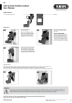
TB1
TB2
Figure 3.1 – Power Supply Module Component Layout
About the PGA Power Supply Module
3-3
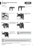
Figure 3.2 – Power Supply Module Functional Block Diagram
3-4
Parallel Gate Amplifier
P/S 2
COM
P/S 1
TW2
TW1
L2
L1
GND
L2
L1
P3
P2
P1
FUSE
8A
B
I
N
P
U
T
A
N
P
U
T
I
LED
PWR OK
OUT TO FAN
OUT TO FAN
EARTH GND
115(N)
115(H)
GATE SIGNALS
GATE SIGNALS
WJ1
28V
SUPPLY
P/S 1
TB2
FUSE
1A
TB1
CONVERSION
28V TO 5V
THERMOSTAT
DCCOM
DCBUS
+5VCOM
+5V
B
A
C
K
P
L
A
N
E
CHAPTER 4
About the PGA Module
The PGA module isolates and amplifies the gate signal pulses received from one of
the two rack backplane channels, A or B. The type of PGA module used depends
upon the channel it will access. An Output-A PGA module (B/M O-60056) receives its
signals from channel A. An Output-B PGA module (B/M O-60071) receives its signals
from channel B. The user must ensure that the correct type of PGA module is used for
the channel desired.
Except for the interface to the rack backplane channels, the two PGA modules are
mechanically and electrically identical, as described in the following sections.
4.1
PGA Module Mechanical Description
The PGA module is a printed circuit board assembly that plugs into slot 3 or 4 (fourslot PGA rack) or slot 3 to 8 (eight-slot PGA rack). One or two modules can be used in
a four-slot rack. Up to six modules can be used in an eight-slot rack. The two types of
modules can be combined in any desired configuration.
Each module consists of a printed circuit board and a faceplate. The top of the
faceplate is labeled "OUTPUT-A" or "OUTPUT-B," to indicate which set of backplane
signals the module will accept. Thumbscrews at the top and bottom of the faceplate
secure the module in the rack. The back of the module plugs into the rack backplane.
The faceplate contains a green "OK" LED indicator and four fifteen-pin female D-shell
connectors. The LED lights to indicate that the +5 VDC supply is present and the
module is functioning normally. The four fifteen-pin D-shell connectors are used to
output the amplified forward or reverse gate signals from the PGA module to the gate
coupling circuits in the Power Modules.
4.2
PGA Module Electrical Description
The PGA module will input the gate signals from its designated channel (A or B) on
the rack backplane. The channel carries the forward or the reverse gate pulses,
depending upon the connection between the DC Power Technology module and the
PGA Power Supply module, as described in chapter 3.
Other than channel selection, both types of PGA module operate identically. The
incoming gate pulses from the six inputs on each channel are optically isolated from
their respective biasing networks and FET gate firing circuits, and physically isolated
from the remaining circuitry on the Power Supply module, backplane, and PGA
module.
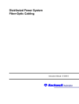
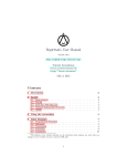
Each of the PGA module’s six FET outputs has a fan-out of four, providing each
module with the capability of driving up to four power bridges. A maximum of six PGA
modules can be used in the system. If all six PGA modules are used, a total of 24
power bridges (6 x 4) can be driven. Figure 4.1 shows one of the four gate signal
outputs.
About the PGA Module
4-1
The standard DC bus voltage is +28 VDC, but the PGA module is capable of handling
DC bus voltages up to +100 VDC, if required by the application. Voltages greater than
the standard +28 VDC must be provided by an externally mounted power supply,
connected to the Power Supply module’s P/S 2 and COM faceplate terminals. See
chapter 3.
The PGA module has one internal fuse. The fuse is not user-serviceable. A blown
fuse indicates that the PGA module has failed and must be replaced.
A functional block diagram of the PGA module is provided in figure 4.2. Specifications
are listed in Appendix C.
4-2
Parallel Gate Amplifier
Power Module
Parallel Gate Amplifier
Gate
Coupler
Circuit
Gate Driver #1
Gate
Coupler
Circuit
Gate Driver #2
Gate
Coupler
Circuit
Gate Driver #3
Gate
Coupler
Circuit
Gate Driver #4
Gate
Coupler
Circuit
Gate Driver #5
Gate
Coupler
Circuit
Gate Driver #6
P1 Connector Shown (P2, P3, and P4 are identical to P1).
Figure 4.1 – PGA Gate Driver Circuitry
About the PGA Module
4-3
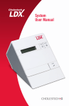
Figure 4.2 – PGA Module Functional Block Diagram
4-4
Parallel Gate Amplifier
B
A
C
K
P
L
A
N
E
DCCOM
DCBUS
+5VCOM
+5V
B GATE SIGNALS
A GATE SIGNALS
FUSE
6
6
(FACTORY
CONFIGURED)
GATE SIGNAL
SELECT
GATE SYMBOLS
OPTO
ISOLATION
GATE DRIVERS
GATE SIGNALS
6
6
GATE SIGNALS
6
6
6
6
6
FOR
B/M 60071
MODULE
FOR
B/M 60056
MODULE
B
LED
P4
P3
P2
P1
A
LED
CHAPTER 5
Installation Guidelines
!
ATTENTION:Only qualified personnel familiar with the construction and
operation of this equipment and the hazards involved should install,
adjust, operate, or service this equipment. Read and understand this
manual and other applicable manuals in their entirety before proceeding.
ATTENTION:The modules in the Parallel Gate Amplifier rack contain
static-sensitive components. Do not touch the module’s circuit board or
the connectors on the back of the module. When not in the rack, the
module should be stored in an anti-static bag.
This section provides guidelines for installing and replacing the PGA rack, the
modules, and the cable assemblies. This section provides general guidelines only.
Always refer to the wiring diagrams supplied with your system for specific installation
information.
5.1
Wiring the PGA Rack
!
ATTENTION: The user is responsible for conforming with all applicable
local, national, and international codes.
The user must ensure that the installation of wiring conforms to all applicable codes.
To reduce the possibility of noise interfering with the control system, exercise care
when installing wiring from the system to external devices. For detailed
recommendations, refer to IEEE Standard 518.
Installation Guidelines
5-1
5.2
Installing the PGA Rack
The rack is designed to be panel-mounted using M6 or 1/4"-20 screws. The holes in
the top flange have a keyhole shape and the lower holes are U-shaped to facilitate
mounting. Refer to figure 5.1 (four-slot rack) or figure 5.2 (eight-slot rack) for mounting
dimensions.
Use the following guidelines when installing the PGA rack:
5-2
•
Ensure that there is enough space for the rack, wiring, terminal strips, and other
devices that must be mounted near the rack.
•
Allow a large enough clearance around the rack to provide access for inspection,
maintenance, and module replacement.
•
Allow 50 mm (2 in) of clearance above and below the rack for ventilation.
•
Do not mount heat-generating equipment underneath the rack.
•
Mount the rack in a vertical position only.
•
The cabling distance between the PGA rack and the Power Module must not
exceed 18.3 m (60 ft).
•
Rack surrounding air temperature must be between 0°C (32°F) and 60°C
(140°F).
•
Relative humidity must be between 5 and 95% (non-condensing).
•
Surrounding air must be clean and dry (e.g., free of flammable or combustible
vapors, chemical fumes, oil vapor, steam, excessive moisture, and dirt).
Parallel Gate Amplifier
Figure 5.1 – Four-Slot PGA Rack Mounting Dimensions
Installation Guidelines
5-3
Figure 5.2 – Eight-Solt PGA Rack Mounting Dimensions
5-4
Parallel Gate Amplifier
5.3
Grounding Considerations
!
ATTENTION: Ungrounded equipment presents a shock hazard. The
ground terminal on the power supply module and the grounding lug on
the rack are not connected together. Connect both points to an external
earth ground.
The ground terminal on the Power Supply module and the grounding lug on the rack
are not connected. Both points must be connected externally to earth ground and
checked with an ohmmeter before power is applied. Use a star washer (toothed lock
washer) to ensure effective grounding. Refer to figure 5.3 (four-slot rack) or figure 5.4
(eight-slot rack) for the location of the Power Supply module ground terminal and the
rack grounding lug.
Figure 5.3 – Location of Power Supply
Ground Terminal and Four-Slot Rack
Grounding Lug
Installation Guidelines
Figure 5.4 – Location of Power Supply Ground Terminal
and Eight-Slot Rack Grounding Lug
5-5
5.4
Module Installation/Replacement Guidelines
!
ATTENTION:Inserting or removing a module or its connecting cables
may result in unexpected machine motion. Turn off power to the PGA
rack before inserting or removing a module or its connecting cables.
ATTENTION:The modules in the Parallel Gate Amplifier rack contain
static-sensitive components. Do not touch the module's circuit board or
the connector on the back of the module. When not in the rack, the
module should be stored in an anti-static bag.
The Power Supply module must be placed in the leftmost slot in the rack. The
remaining slots are used for the PGA modules.
Observe the following guidelines when installing or removing a module:
5.5
•
Ensure that power to the rack as well as power to the wiring leading to the rack is
off.
•
Use the metal guides provided in the rack to facilitate sliding the module into and
out of the rack.
•
Use care when inserting a module into the rack to avoid bending the connector
pins.
•
Ensure that the module is well seated in the rack. Use the thumbscrews provided
at the top and bottom of the module faceplate to secure the module to the rack.
•
The individual modules are not enclosed; therefore, a module's circuit board is
exposed when it is out of the PGA rack. Wear a ground strap and handle the
module by the edges only. When not in use, the module should be stored in an
anti-static bag.
Installing the PGA Power Supply Module
The following sections describe the input power and fan connections for the PGA
Power Supply module and the cabling between the PGA Power Supply module and
the PMI DC Power Technology module.
!
5-6
ATTENTION: The PGA power supply module operates using AC input
voltage capable of producing severe shock. Make certain that the
external AC supply circuit is turned off before inserting or removing the
module or connecting any wires or cables.
Parallel Gate Amplifier
5.5.1 Connecting AC Input Power
The 115 VAC Input terminals on the Power Supply module must be wired to the AC
power source using twisted-pair wire. Refer to table 5.1 when connecting AC input
power to the Power Supply module.
Table 5.1 – Input Power Connections
Wire Color
Wire Label
115VAC Input
Red
AC Line High
L1
White
AC Line Neutral
L2
Green
Earth Ground
NOTE: The PGA rack is shipped with the fan internally connected to the L1 and L2
terminals labeled "115 VAC OUTPUT TO FAN."
5.5.2 Installing an Optional External Supply Greater Than +28 VDC
In the rare case that the +28 VDC supply does not supply sufficient power to fire the
gate coupling circuits in the Power Module, an external supply of up to +100 VDC may
be used. The power supply’s output current must be limited to 10A. To add the
external supply to the system, jumpers TB1 and TB2 on the Power Supply module’s
printed circuit board must be configured as described below. Refer to figure 3.1.
•
TB1: Disconnect the jumper from the INTERNAL terminal (the default setting).
Connect the jumper from COMMON to the EXTERNAL P/S 2 terminal.
•
TB2: Insert a jumper between the two terminals of TB2 (EXT and P/S COM).
The regulated external power supply should be mounted at an appropriate location as
described by the manufacturer. It should be connected to terminals P/S 2 and COM on
the Power Supply module's faceplate through an appropriate filter network, as shown
in Appendix E.
•
Connect the regulated external power supply's positive output to terminal P/S 2.
•
Connect the regulated external power supply's common to the COM terminal.
5.5.3 Connecting the PMI DC Power Technology Module to the PGA
Power Supply Module
For a regenerative drive, both the forward and reverse gate signals from the PMI DC
Power Technology module are connected to the PGA Power Supply module's
faceplate connectors. For a non-regenerative drive, only the forward gate signals are
used. The part numbers of the forward and reverse gate cables are stamped onto the
cables and should be compared to the wiring diagrams shipped with your system.
Each cable has a 14-pin male connector on one end that mates with one of the DC
Power Technology module's faceplate connectors. The connectors contain key pins to
ensure that the forward and reverse cables are not connected to the wrong signals.
Near the connector, each cable is normally labeled "C4-Pn," where n is the DC Power
Technology module's connector number. For example, the forward gate signal cable
labeled C4-P2 mates with the P2 connector.
Installation Guidelines
5-7
The other end of each cable has a fifteen-pin female D-shell connector that mates with
the faceplate connectors on the PGA Power Supply module. The forward gate signal
cable should be connected to Input A and the reverse gate signal cable to Input B.
Appendix F provides a list of the Power Supply module cables used with the PGA
system. Note that the Power Supply cable length must not exceed 3.7 m (12 ft).
Refer to the wiring diagrams supplied with your system for the connection instructions
specific to your installation.
5.6
Connecting the PGA Module to the Gate Coupling
Circuits
The cables that are required for connecting the PGA modules to the gate coupling
circuits are specific to your drive system. Each cable is supplied with a 15-pin male
D-shell connector on one end that mates with the PGA module’s faceplate connector.
The cable connectors are color-coded black for Output-A type PGA modules and gray
for Output-B type. The other end of the cable is supplied with either a Cannon™ round
connector plug (cable #612436 or #612567) or an Elco™ square connector plug
(cable #612434 or #612566) to mate with the connector on the DC Power Module.
If needed, a cable (#612435) with individual connectors for the six gate coupling
circuits on the Power Module can be supplied as well. This cable mates with the
connector plug on the end of cable #612436 (Output-A) or #612567 (Output-B).
Table 5.2 describes the gate signals that are transmitted via these cables. The
connector plug is shown in figure 5.5.
Appendix F provides a list of the PGA cables that can be supplied with the system.
Note that the total cable length from the PGA module to the gate coupling circuit must
not exceed 18.3 m (60 ft).
5-8
Parallel Gate Amplifier
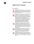
Table 5.2 – Connection Sequence for Cable Assemblies 612436 and 612567
Thyristor 1:
Thyristor 2:
Thyristor 3:
Thyristor 4:
Thyristor 5:
Thyristor 6:
Signal
From D-Shell
Connector Pin
Wire Color
To Gate Driver
Plug Pin
Gate 1
5
BRN
1
DC Bus
15
WHT/BRN
2
Gate 2
4
RED
3
DC Bus
14
WHT/RED
4
Gate 3
3
ORG
5
DC Bus
13
WHT/ORG
6
Gate 4
2
YEL
9
DC Bus
12
WHT/YEL
10
Gate 5
7
GRN
11
DC Bus
11
WHT/GRN
12
Gate 6
1
BLU
13
DC Bus
6
WHT/BLU
14
Figure 5.5 – Gate Driver Plug for Cable Assemblies 612436 and 612567
Figure 5.6, on the following page, shows a typical example of PGA module cabling.
Refer to the wiring diagrams shipped with your system for the connection instructions
specific to your installation. The cable part numbers are stamped onto the cables and
should be compared to those listed in the wiring diagrams.
Installation Guidelines
5-9
Figure 5.6 – PGA System Hardware Connections
5-10
Parallel Gate Amplifier
APPENDIX A
Rack Specifications
Ambient Conditions
•
Operating temperature: 0 to 40°C (32 to 104°F) ambient allowing for a maximum
20°C (36°F) temperature rise inside enclosure
•
Storage temperature: - 30 to 85°C (-22 to +185°F)
•
Humidity: 5 to 95% non-condensing
Rack Dimensions
Four-Slot Rack with Fan
•
Height: 290 mm (11.5 in)
•
Width: 180 mm (7.09 in)
•
Depth: 184 mm (7.25 in)
Eight-Slot Rack with Fan
•
Height: 290 mm (11.5 in)
•
Width: 324 mm (12.75 in)
•
Depth: 184 mm (7.25 in)
Bus Specifications
•
Type: Proprietary
Fan Assembly
805400-17R (four-slot Rack)
805400-18R (eight-slot Rack)
Rack Specifications
•
Input voltage: 115 VAC +/-10% (103 - 126 VAC)
•
Frequency: 50/60 Hz (47- 63 Hz)
•
Power Dissipation: 14/11 W
A-1
A-2
Parallel Gate Amplifier
APPENDIX B
Power Supply Module
Specifications
Ambient Conditions
•
Operating temperature: 0 to 40°C (32 to 104°F) ambient allowing for a maximum
20°C (36°F) temperature rise inside enclosure
•
Storage temperature: - 30 to 85°C (-22 to +185°F)
•
Humidity: 5 to 95%, non-condensing
Maximum Module Power Dissipation
•
30 W
Dimensions
•
Height: 205 mm (8.063 in)
•
Width: 103.0 mm (4.055 in)
•
Depth: 178.8 mm (7.039 in)
Maximum Source KVA
•
10
Short Circuit Limitation
•
10,000 VA
Power Requirements
•
Input voltage: 115VAC +/-10% (103 - 126 VAC)
•
Current: 2.0A maximum
•
Frequency: 47- 63 Hz
•
Input protection: Fuse (8 A, fast-acting)
Temperature Sensor TW1, TW2 Contact Ratings
•
115VAC, 2A, 47-63 Hz
Power Supply Module Specifications
B-1
DC Outputs
5 Volt supply:
•
Output voltage: 5V (+/- 1%): 0 - 2 A @ 60 °C
•
Line regulation: 0.2% (18V - 36V)
•
Load regulation: 1% (0 to full load)
•
Noise ripple: 75 mV
•
Efficiency: 78%
•
Overcurrent protection: Can sustain short circuit indefinitely
•
Overvoltage protection: Overvoltage clamping @ 6.2 - 6.5V
•
Protection: Fuse (not user-serviceable)
28 Volt supply:
•
Output voltage: 28V (+/- 5%):0 - 5A @ 40°C, 0 - 4.4A @ 50°C, 0 - 3.7A @ 60°C
•
Line regulation: 0.1% (103V - 126V)
•
Load regulation: 0.1% (0 to full load)
•
Noise ripple: 150 mV
•
Efficiency: 80% (minimum)
•
Overcurrent protection: Constant current (above 50% Vout)
Current feedback (below 50% Vout)
•
Holdover time: 16.7 mS (max load, low line)
Optional External P/S 2 Power Supply Ratings
B-2
•
Input voltage: 100 VDC max
•
Input current: 2.3A (rms)
•
External fuse: 10A, 250V
Parallel Gate Amplifier
APPENDIX C
PGA Module Specifications
Ambient Conditions
•
Operating temperature: 0 to 40°C (32 to 104°F) ambient allowing for a maximum
20°C (36°F) temperature rise inside enclosure
•
Storage temperature: - 30 to 85°C (-22 to +185°F)
•
Humidity: 5 to 95%, non-condensing
Dimensions
•
Height: 205 mm (8.063 in)
•
Width: 35 mm (1.375 in)
•
Depth: 174 mm (6.813 in)
Maximum Module Power Dissipation
•
3W
Maximum Module Power Requirements
•
+28V @ 5A
Coupler Circuits Using 28V Supply
•
B/M O-60072 (High Output Gate Driver)
Open circuit voltage (Voc): 12V nominal
Short circuit current (Isc): 1000 mA nominal
Isolation voltage: 1200V
•
B/M O-60073 (1)
Open circuit voltage (Voc): 12V nominal
Short circuit current (Isc): 700 mA nominal
Isolation voltage: 1200V
(1) Replaces B/M O-51378-19
Coupler Circuits Using External P/S 2 Supply (Maximum Conditions)
PGA Module Specifications
•
Open circuit voltage (Voc): 100V max
•
Short circuit current (Isc): 1300 mA max
C-1
PGA Output Loading vs. Temperature
Number of Power Boxes Permitted
(4 Boxes per PGA Module)
25
20
Gate Coupler B/M O-60073
15
At Maximum Conditions
Gate Coupler B/M O-60072
10
5
0
0
10
20
30
40
50
60
Surrounding Temperature
(°C)
C-2
Parallel Gate Amplifier
APPENDIX D
PGA Maximum System Power
Requirements
1 PGA
MODULE
2 PGA
MODULES
3 PGA
MODULES
4 PGA
MODULES
5 PGA
MODULES
6 PGA
MODULES
POWER SUPPLY &
FAN
30 VA
30 VA
30 VA
30 VA
30 VA
30 VA
PGA MODULES
48 VA
96 VA
144 VA
192 VA
240 VA
288 VA
MAXIMUM SYSTEM
POWER REQUIRED
78 VA
126 VA
174 VA
222 VA
270 VA
318 VA
NOTE: These values apply when using Reliance B/M O-60073 gate coupling circuits.
Values may vary if using other gate coupling circuits.
PGA Maximum System Power Requirements
D-1
D-2
Parallel Gate Amplifier
External PGA Power Supply Interface
FUSE
INDUCTOR
CAPACITOR
PGA EXTERNAL POWER SUPPLY INTERFACE BOARD
FUSE
COM (P3-9)
TO RACK
POWER SUPPLY
PS2 (P3-10)
DESCRIPTION
92uH, 6A
ALUM. ELEC., 1000 F,m200V
CLASS CC, TIME DELAY, 10A, 300V DC
PANEL MOUNT
PCB MOUNT, 10A, 300V
COMPONENT
INDUCTOR
CAPACITOR
FUSE
FUSE BLOCK
TERM. BLOCK
TOKIN
UNITED CHEM CON
LITTELFUSE
LITTELFUSE
WEIDMULLER
MANUFACTURER
SN-13-400
KMH200VN102M35X35
KLDR 10
L60030C-1
GS 5/4
MFG. P/N
602920-5E
69957-233SA
64676-64AG
49454-19A
49455-108D
REL. P/N
IF THE PRINTED CIRCUIT BOARD IS REQUIRED, CONSULT WITH
DEVELOPMENT ENGINEERING.
NOTE: AS OF THE WRITING OF THIS MANUAL, THE PRINTED CIRCUIT
BOARD THAT CONTAINS THESE PARTS HAS NOT YET BEEN
COMPLETED.
1
2
1
1
2
EXTERNAL
DC POWER SUPPLY
(28-100 VDC)
+
QTY
*FUSE SIZE DETERMINED BY
POWER SUPPLY MANUFACTURER
GND
L2
L1
APPENDIX E
External PGA Power Supply
Interface
E-1
E-2
Parallel Gate Amplifier
APPENDIX F
Replacement Parts
PGA Rack/Backplane
Part or
Assy #
Description
Rack
Enclosure
Fan Assembly
Backplane
805401-6S
4-Slot PGA Rack Assembly with Fan
805400-R
805400-17R
O-60060
805401-8S
8-Slot PGA Rack Assembly with Fan
805400-14R
805400-18R
O-60057
Modules
Part or
Assy #
Description
O-60055
PGA Power Supply Module
O-60056
Output-A PGA Module
O-60071
Output-B PGA Module
707311-94R
Blank Faceplate Assembly
Connector Cables (cable length xxx is specified in inches)
Base P/N
Description/Connections
612432-xxxS(1)
Forward DC Gate Signals; DC Tech. Module P2 to PGA Power Supply Module P1
612433-xxxS(1)
Reverse DC Gate Signals; DC Tech. Module P3 to PGA Power Supply Module P2
612434-xxxS(2)
PGA Module Output-A to DC Power Module (Elco square receptacle)
612435-(3)
Cable Assemblies 612436 / 612567 to Gate Coupling Circuits
612436-xxxS(2)
PGA Module Output-A to DC Power Module (Cannon round receptacle)
612566-xxxS(2)
PGA Module Output-B to DC Power Module (Elco square receptacle)
612567-xxxS(2)
PGA Module Output-A to DC Power Module (Cannon round receptacle)
(1)
Maximum length not to exceed 3.7 m (144 in).
Maximum length not to exceed 18.3 m (720 in).
(3) Wire lengths for each gate coupling circuit are specified in bill of material. Maximum length not to exceed 3 m (120 in).
(2)
Replacement Parts
F-1
Cable assemblies are available in the following standard lengths:
Cable Assy.
Length (inches)
Part Number
612432-
13
612432-013S
612433-
13
612433-013S
612434-
60
612434-060S
96
612434-096S
60
612436-060S
96
612436-096S
120
612436-120S
60
612566-060S
96
612566-096S
60
612567-060S
96
612567-096S
120
612567-120S
612436-
612566-
612567-
Note that cable assembly 61235 does not have a defined standard
length as its individual lengths of twisted pairs may all vary.
F-2
Parallel Gate Amplifier
INDEX
C
Cables
cable assemblies, 5-9, F-2
connector cables, F-1
PGA module cables, 5-8, 5-9, F-1
Power Supply module cables, 5-8, 5-9, F-1
D
DPS documentation, 1-4
rack, 5-1
wiring, 5-1
O
Output-A PGA Module, 1-1, 4-1
Output-B PGA Module, 1-1, 4-1
P
Gate coupling circuits, 1-1, 5-8
Grounding. See Installation
parallel motoring and regenerating example, 1-7
PGA modules
electrical description, 4-1
functional block diagram, 4-4
gate driver circuitry, 4-3
mechanical description, 4-1
PGA system, 1-7
configurations, 1-3
hardware connections, 5-10
overview, 1-1
Power supply
external, 3-1, 5-7, E-1
requirements, D-1
Power Supply module
component layout, 3-3
electrical description, 3-2
functional block diagram, 3-4
ground terminal, 5-5
mechanical description, 3-1
I
R
Input power connections. See Installation
Installation, 5-1 to 5-10
AC input power, 5-7
connecting to DC Power Technology module,
5-7
connecting to gate coupling circuits, 5-8
external power supply, 5-7
grounding, 5-5
guidelines, 5-1
module installation/replacement, 5-6
mounting dimensions, 5-3, 5-4
PGA module, 5-6
Power Supply module, 5-6
Rack
eight-slot PGA rack and modules, 1-6
eight-slot PGA rack mounting dimensions, 5-4
electrical description, 2-1
four-slot PGA rack and modules, 1-5
four-slot PGA rack mounting dimensions, 5-3
grounding lug, 5-5
mechanical description, 2-1
Related hardware and software, 1-2
Related publications, 1-4
Replacement parts, F-1
E
External power supply
installing, 5-7
interface, E-1
F
Fuse
PGA module, 4-2
Power Supply module, 3-2
G
Index
Index-1
S
Standard features, 1-2
System power requirements, D-1
T
Technical specifications
PGA module, C-1
PGA rack, A-1
Power Supply module, B-1
W
Wiring. See Installation
Index-2
Parallel Gate Amplifier
Rockwell Automation / 24703 Euclid Avenue / Cleveland, Ohio 44117 / (216) 266-7000
Printed in U.S.A.
S-3045-2
July 1999