Transcript
V442 / V448 | Plastic Ball Valve Lockout
User Manual
Material Content:
a. Plastic Ball Valve Lockout V442
a. Plastic Ball Valve Lockout V448
Parts X
Parts X
Parts Y
Parts Y
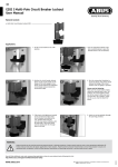
Application:
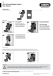
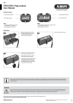
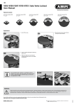
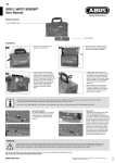
1.Turn the valve handle to the off
position.
1.
3. Slide part Y on to part X to connect
the two halves of the ball valve lock.
The valve handle must be enclosed
above, below and at the sides in this
case.
3.
5. Insert a padlock through the hole
which allows the closest fit.
5.
6. Make sure that the valve handle is
tightly enclosed and can no longer
be moved.
2. Attach part X from above to the
valve handle so that the lock tightly
encloses the valve body and the
valve handle.
2.
4. Press the two halves together until
the valve is tightly enclosed.
4.
Part X is equipped internally with a height limit for standard
valve handles. If your valve handle is thicker, you can remove
this height limit at four predetermined breaking points using
a screwdriver.
WARNING:
Product should only be used by personnel properly trained in lockout procedures. Product should only be used on the appropriate application (s).
Follow product instructions for proper application of each product. Properly trained personnel should check to ensure that product is secure and
equipment will not operate. Failure to follow product instructions and warnings may result in serious bodily inury or death.
www.abus.com
Subject to technical alterations. No liability for mistakes and printing errors.
ABUS | D 58292 Wetter | Germany
©
07/2015
You will find additional notes and corresponding application videos to every lockout device following the link:
http://www.abus.com/eng/Service/Videos/Industrial-safety