1
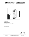
GA-SRP(H)135-024
Direct coupled, spring return actuators, 135 in-lb
User Manual
December, 2003
ISO 9001
Customer Service (858) 761-9331
Fax (858) 578-4633
B u y C o n t r o l s . u s
9730 Distribution Avenue, San Diego, CA 92121
Specification subject to change without notice.
Printed in Germany
User Manual - GA-SRP(H)135-024
Page 3
page
1 Application ............................................................................................................................4
2 Safety remarks......................................................................................................................4
3 Installation.............................................................................................................................4
4 Wiring configuration GA-SRP135-024, Proportional control............................................5
5 Wiring configuration GA-SRPH135-024, Proportional control .........................................6
6 Change of control direction ................................................................................................7
7 Manual lock and manual unlock .........................................................................................7
8 Dimensions ...........................................................................................................................8
9 Ordering information............................................................................................................8
10 Specifications .......................................................................................................................9
Customer Service (858) 761-9331
Fax (858) 578-4633
B u y C o n t r o l s . u s
9730 Distribution Avenue, San Diego, CA 92121
Specification subject to change without notice.
Printed in Germany
User Manual - GA-SRP(H)135-024
Page 4
Direct coupled, spring return actuators, 135 in-lb
1
Application
Actuators may be easily installed by direct shaft mounting on air dampers, shutters and butterfly valves in
ventilation and air conditioning systems. The mechanical spring return function operates only upon a power
failure or power interruption caused by an unsafe condition. The actuators can be controlled by any compatible electric or electronic analog controller, DDC/PLC control or automation system.
2
Safety remarks
The actuators are not suitable for use in explosive atmospheric applications!
All service to the actuators (mounting, electrical connection, retrofitting and repair) must be carried out with the
power supply disconnected. The electrical connection must be done by a trained and competent person considering the wiring diagrams, local and national regulations. Use copper twisted conductors only.
If using electrical conduit, the attachment to the actuator must be made with flexible metal conduit.
Provide disconnect and overload protection if necessary.
This actuator may only be operated by 24 VAC/VDC!
The transformer must be sized according to technical data of the actuator (see section 10). Electronics and
controllers must be powered from a separate transformer when controller power is full-wave rectified. Otherwise
the controller or the actuator may be damaged.
Always read the controller installation instructions before making any connection!
3
Installation
Direct mounting with V-bolt clamp to the damper shaft and fixing with enclosed anti-rotation mounting bracket.
Shaft:
Ø 3/8" to 3/4" (Ø 9 - 20 mm)
3/8" to 5/8" ( 9 - 16 mm)
Attention!
Actuator will be delivered for clockwise rotation when control signal is applied - reverse mounting for
counterclockwise rotation.
Change of rotation direction by reversed mounting
1. Remove the snap ring.
2. Pull out the V-bolt clamp assembly from the actuator towards outside.
3. Push the V-bolt clamp assembly from the opposite face.
4. Refit the snap ring.
Mounting "clockwise rotation"
Customer Service (858) 761-9331
Fax (858) 578-4633
Mounting "counterclockwise rotation"
B u y C o n t r o l s . u s
9730 Distribution Avenue, San Diego, CA 92121
Specification subject to change without notice.
Printed in Germany
User Manual - GA-SRP(H)135-024
4
Page 5
Wiring configuration GA-SRP135-024, proportional control
Notes:
• Actuators are provided with color coded wires. Wires for optional switches are number coded.
• Observe polarity on secondary of transformers. All common and signal (–) must be connected in line.
Incorrect polarity can cause controller damage or operation error.
• Long wire runs requires a 4-wire configuration (connect common for power and control signal at the
actuator or close by). Greater than a 0.2 V drop must be avoided for any common wire.
• Always use a separate transformer when controller power is full-wave rectified.
• Controller and actuators must have separate transformers for paralleled multi-actuator application.
• Use copper twisted conductors only.
• If using electrical conduit, the attachment to the actuator must be made with flexible metal conduit.
• Provide overload protection for line voltage and disconnect as required.
• Power supply and auxiliary switch connections meet UL and CSA requirements without the need of
an electrical ground connection.
com
+
Y
U
wht
grn
~
blk
red
(+) U, Feedback Signal*
Line L2
(-)
2-10 VDC
* Signal can provide position
indication or master-slave
applications
Volts L1
(-) (+)
24 VAC
Transformer
Y, Control signal
2-10 VDC, or
4-20 mA w/500 Ω resistor between
com (blk) and Y control signal (wht)
Option S2
S1
1
2
(2) Auxiliary switches, SPDT, 250 VAC, 5 (2.5) A,
w/ adjustable cam for setting between 0 - 72° and
18 - 90°.
S2
3
5
4
6
Factory set: S1 @ 4.5°
S2 @ 72.0°
Selection of direction
Spring return CCW or CW mounted
Multiple actuators
(maximum quantities)
Pos. of
select.
Proportional control
Signal Y
Stacking (torque is additive)
4
Parallel connection, 2-10 VDC
20
Parallel connection, 4-20 mA,
w/500 Ω resistor
10
Master-slave,
via U, feedback signal
10
Angle of
rotation
CW
0-90°
2-10 VDC
CCW
90-0°
2-10 VDC
Customer Service (858) 761-9331
Fax (858) 578-4633
B u y C o n t r o l s . u s
9730 Distribution Avenue, San Diego, CA 92121
GA-SRP135-024
Proportional
Specification subject to change without notice.
Printed in Germany
User Manual - GA-SRP(H)135-024
5
Page 6
Wiring configuration GA-SRPH135-024, proportional control
Notes:
• Actuators are provided with number coded wires.
• Observe polarity on secondary of transformers. All common and signal (–) must be connected in line.
Incorrect polarity can cause controller damage or operation error.
• Greater than a 0.2 V drop must be avoided for any common wire.
• Controller and actuators must have separate transformers.
• Use copper twisted conductors only.
• If using electrical conduit, the attachment to the actuator must be made with flexible metal conduit.
• Provide overload protection for line voltage and disconnect as required.
• Power supply and auxiliary switch connections meet UL and CSA requirements without the need of
an electrical ground connection.
com
1
+
(P1) (P2) (P3)
U
~
W
R
B
~
2
3
4
5
6
(+)
U, Feedback Signal*
(-)
2-10 VDC
135 Ω
Line L2
Volts L1
24 VAC
Transformer
W
R
B
Controller
* Signal can provide position
indication or master-slave
applications
Line L2
Volts L1
24 VAC
Transformer
Selection of direction for spring return and motor
• Spring return reversible with CCW or CW
mounting
• Motor reversible with CCW/CW selector, built-in
actuator cover
Selection of direction
Spring return CCW or CW mounted
Multiple actuators
(maximum quantities)
Pos. of
select.
Angle of
rotation
Proportional control
Signal Y
Stacking (torque is additive)
4
20
CW
0-90°
0-135 Ω
Parallel connection, 0-135 Ω,
proportional
CCW
90-0°
0-135 Ω
Master-slave,
via U, feedback signal
10
Customer Service (858) 761-9331
Fax (858) 578-4633
B u y C o n t r o l s . u s
9730 Distribution Avenue, San Diego, CA 92121
GA-SRPH135-024
Proportional
Specification subject to change without notice.
Printed in Germany
User Manual - GA-SRP(H)135-024
6
Page 7
Change of control direction
mounting side
CCW
CW
direction of rotation switch
CCW
CW
at
Y=0
7
CCW
CW
at
Y=0
CCW
CW
at
Y=0
CCW
CW
at
Y=0
Manual lock and manual unlock
mounting side
CCW
CW
manual lock / manual unlock
UNLOCK
UNLOCK
LOCK
LOCK
Manual lock
Turn the manual winding tool quickly opposite to
direction of rotation!
Manual unlock
Turn the manual winding tool in direction of rotation!
Customer Service (858) 761-9331
Fax (858) 578-4633
B u y C o n t r o l s . u s
9730 Distribution Avenue, San Diego, CA 92121
Specification subject to change without notice.
Printed in Germany
User Manual - GA-SRP(H)135-024
Dimensions
0.94
[24]
1.71
[43]
0.59
[15]
0.14
[4]
0.08
[2]
2.28
[58]
3.27
[83]
0.08
[2]
0.84
[21]
8
Page 8
R
[R 0.4
12 7
]
0.39
[10]
3.86
[98]
0.24
[6]
4"
Ø3/ 0]
2
[Ø
M0.24
[6]
47
0. ]
R R12
[
manual override
Note:
Anti-rotation mounting
bracket and 3 mm hex
crank for manual override
supplied w/actuator
9.84
[250]
9
inches [mm]
Ordering information
GA-SRP135-024
GA-SRP135-024-S2
Standard
w/(2) auxiliary switches
Customer Service (858) 761-9331
Fax (858) 578-4633
GA-SRPH135-024
B u y C o n t r o l s . u s
9730 Distribution Avenue, San Diego, CA 92121
Standard
Specification subject to change without notice.
Printed in Germany
User Manual - GA-SRP(H)135-024
Page 9
10 Specifications
Control
Input signal
· GA-SRP135-024
· GA-SRPH135-024
Input impedance
· GA-SRP135-024
Feedback signal
Electrical
Power supply
Over voltage
Power consumption
- holding
Performance
Torque
Damper size
Angle of rotation
· direction
Rotation time
· actuator rotation
· spring return
Power failure
Position indicator
Synchronization
Overload protection
Manual override
Proportional
2-10 VDC, or
4-20 mA *w/500 Ω resistor
Proportional
0-135 Ω Honeywell
series 90 or a 0-135 Ω
input
Physical
Enclosure
· cover plates
· base
· color
· protection
Mounting position
Anti-rotation bracket
Stacking/paralleling
100 kΩ
2-10 VDC, 0.5 mA
Clamp connection to
· round shaft
24 VAC/VDC ± 20%,
50/60 Hz
Up to 40 V, max. 5 sec.
7.0 W (9.0 VA)
4.0 W
· square shaft
135 in-lb (15 Nm)
Up to 34 sq. ft. (3.0 m2)
100° (-5 to 95°)
Spring return can be
selected by CCW/CW
mounting
< 150 sec/0-90°
< 20 sec/90-0°
Spring return to -5° position
Visual scale
± 1%
Electronic throughout
rotation
3 mm hex crank, shipped
w/actuator
Noise level
· motor
Max. 50 dB(A)
· spring return
Max. 62 dB(A)
Environmental
Permissible ambient
· working temperature -22°F to 122°F
(-30°C to 50°C)
· storage temperature -40°F to 176°F
(-40°C to 80°C)
· humidity
5-95% RH, non-condensing
Customer Service (858) 761-9331
Fax (858) 578-4633
Wire connection
· option on request
Wire size
Conduit connector
Dimensions
Weight
Manufacturing
Listings/Approvals
Warranty
Zinc coated steel
PA 6.6
Silver and black
NEMA 2
Any position
Included w/actuator
Refer to table
“Multiple Actuators”
Ø 3/8" to 3/4"
(9 to 20 mm)
3/8" to 5/8"
(9 to 16 mm)
3 ft. (0.9 m) appliance
cable.
GA-SRP color coded
GA-SRPH number coded
Plenum rated cable
18 AWG (0.75 mm2)
1/2", built-in
9.84 x 3.86 x 2.28 in.
(250 x 98 x 58 mm)
4.4 lbs. (2.0 kg)
ISO 9001 certified
CE
UL and CSA
Five-year material and
workmanship
(Two-year standard,
three-year conditional)
Options
GA-SRP135-024
· S2 (2) Aux. switch
built-in
B u y C o n t r o l s . u s
9730 Distribution Avenue, San Diego, CA 92121
SPDT 250 VAC, 5 (2.5) A,
position adj. between 0-72°
and 18-90°, incl. 3 ft.
(0.9 m) appliance cable,
number coded, and 1/2"
conduit connector
Specification subject to change without notice.
Printed in Germany