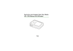
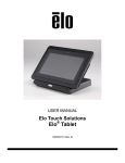
1
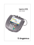
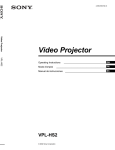
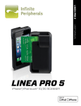
SecurePIN User Manual
USER MANUAL
TM
SecurePIN
Hand Held, Encrypting
PIN Entry Device
Models 100, 130, 150, & 180
,
, PCI
80071501-001-D
03-27-2009
Copyright © 2006, International Technologies & Systems Corp. All rights reserved.
SecurePIN User Manual
FCC WARNING STATEMENT
This equipment has been tested and found to comply with the limits for a Class B digital
device, pursuant to Part 15 of FCC Rules. These limits are designed to provide
reasonable protection against harmful interference when the equipment is operated in a
commercial environment. This equipment generates, uses, and can radiate radio
frequency energy and, if not installed and used in accordance with the instruction
manual, may cause harmful interference to radio communications.
FCC COMPLIANCE STATEMENT
This device complies with Part 15 of the FCC Rules. Operation of this device is subject
to the following conditions: this device may not cause harmful interference and this
device must accept any interference received, including interference that may cause
undesired operation.
CANADIAN DOC STATEMENT
This digital apparatus does not exceed the Class B limits for radio noise for digital
apparatus set out in the Radio Interference Regulations of the Canadian Department of
Communications.
Le présent appareil numérique n’émet pas de bruits radioélectriques dépassant les
limites applicables aux appareils numériques de las classe B prescrites dans le
Réglement sur le brouillage radioélectrique édicté par les ministère des
Communications du Canada.
CE STANDARDS
An independent laboratory performed testing for compliance to CE requirements. The
unit under test was found compliant to Class B.
Copyright © 2006, International Technologies & Systems Corp. All rights reserved.
Page 2 of 18
SecurePIN User Manual
LIMITED WARRANTY
ID TECH warrants to the original purchaser for a period of 12 months from the date of
invoice that this product is in good working order and free from defects in material and
workmanship under normal use and service. ID TECH’s obligation under this warranty
is limited to, at its option, replacing, repairing, or giving credit for any product which has,
within the warranty period, been returned to the factory of origin, transportation charges
and insurance prepaid, and which is, after examination, disclosed to ID TECH’s
satisfaction to be thus defective. The expense of removal and reinstallation of any item
or items of equipment is not included in this warranty. No person, firm, or corporation is
authorized to assume for ID TECH any other liabilities in connection with the sales of
any product. In no event shall ID TECH be liable for any special, incidental or
consequential damages to purchaser or any third party caused by any defective item of
equipment, whether that defect is warranted against or not. Purchaser’s sole and
exclusive remedy for defective equipment, which does not conform to the requirements
of sales, is to have such equipment replaced or repaired by ID TECH. For limited
warranty service during the warranty period, please contact ID TECH to obtain a Return
Material Authorization (RMA) number & instructions for returning the product.
THIS WARRANTY IS IN LIEU OF ALL OTHER WARRANTIES OF
MERCHANTABILITY OR FITNESS FOR PARTICULAR PURPOSE. THERE ARE NO
OTHER WARRANTIES OR GUARANTEES, EXPRESS OR IMPLIED, OTHER THAN
THOSE HEREIN STATED. THIS PRODUCT IS SOLD AS IS. IN NO EVENT SHALL
ID TECH BE LIABLE FOR CLAIMS BASED UPON BREACH OF EXPRESS OR
IMPLIED WARRANTY OF NEGLIGENCE OF ANY OTHER DAMAGES WHETHER
DIRECT, IMMEDIATE, FORESEEABLE, CONSEQUENTIAL OR SPECIAL OR FOR
ANY EXPENSE INCURRED BY REASON OF THE USE OR MISUSE, SALE OR
FABRICATIONS OF PRODUCTS WHICH DO NOT CONFORM TO THE TERMS AND
CONDITIONS OF THE CONTRACT.
The information contained herein is provided to the user as a convenience. While every
effort has been made to ensure accuracy, ID TECH is not responsible for damages that
might occur because of errors or omissions, including any loss of profit or other
commercial damage, nor for any infringements or patents or other rights of third parties
that may result from its use. The specifications described herein were current at the
time of publication, but are subject to change at any time without prior notice.
ID TECH is a registered trademark of International Technologies & Systems
Corporation. SecurePIN and Value through Innovation are trademarks of International
Technologies & Systems Corporation.
ID TECH
10721 Walker Street
Cypress, CA 90630
(714) 761-6368
Copyright © 2006, International Technologies & Systems Corp. All rights reserved.
Page 3 of 18
SecurePIN User Manual
TABLE OF CONTENTS
1.0 Introduction
2.0 Features & benefits
3.0 Product configurations
4.0 Terms, Standards & Related Documents
4.1
Glossary
4.2
Related Documents
4.3
Standards
5.0 Installation
5.1
Cable Installation
5.2
RS232 Units
5.3
USB Units
6.0 Operation
6.1
Power-Up Sequence
6.2
Operational States
6.3
Audio
6.4
User Parameter Selections
6.5
SecurePIN Operation
6.6
Idle Screen
6.7
Power Saver Mode
6.8
Card Reading
6.9
PIN Entry
7.0 Maintenance
7.1
Back up battery
8.0 Troubleshooting
8.1
Power-Up Display
8.2
Configuration Display Mode
8.3
Diagnostic Mode
9.0 Appendix A Specifications
9.1
Power Requirements
9.2
Operating Environment
9.3
Mechanical
9.4
Encryption & Key Management
9.5
Communication Interface
9.6
Reliability
9.7
Approvals
10.0 Appendix B Unit Configuration Table
11.0 Appendix C Language Options Table
12.0 Appendix D Message Explanations
5
5
5
7
7
7
7
9
9
9
9
10
10
10
11
11
12
12
12
12
12
13
13
13
13
14
14
15
15
15
15
16
16
16
16
17
18
18
Copyright © 2006, International Technologies & Systems Corp. All rights reserved.
Page 4 of 18
SecurePIN User Manual
1.0
Introduction
SecurePIN is a Payment Card Industry (PCI) certified Personal Identification Number
(PIN) Entry Device that encrypts a PIN for secure transmission to a POS terminal or
similar equipment. The SecurePIN is primarily used in POS applications where a PIN is
required for transaction authorization. This document provides the information for
installing and using the SecurePIN product. A separate document is available for API
software interface support.
There are four SecurePIN models. SecurePIN 100 is a basic PED, the SecurePIN 130
includes a MagStripe reader, the SecurePIN 150 has an EMV compatible Smart Card
reader, and the SecurePIN 180 comes with both Smart Card & MagStripe readers.
2.0
o
o
o
o
o
o
o
o
o
o
o
o
o
3.0
Features & benefits
Ergonomic Hand Held Unit with an easy to use design
Some models have integrated smart card & MagStripe readers
Keys are a comfortable size and have good tactile feel
Provides audio Feedback for each key stroke
Telephone layout for number keys & color-coded control keys
Interaction function keys for application specific functions
Provides a two lines by 12 character LCD backlit display
Payment Card Industry (PCI) security requirements certified
Meets ANSI and ISO standards for a PIN Entry Device (PED)
Supports DES and TDES encryption algorithms for PIN encryption
Provides DUKPT Key Management operations
Tamper evident, tamper resistant, & tamper responsive design
Application selectable language options for PIN entry prompt
Product configurations
The SecurePIN product has four model number configurations.
Model #
SecurePIN 100
SecurePIN 130
SecurePIN 150
SecurePIN 180
Model Number
IDPA-50y100Y
IDPA-53y1xx
IDPA-55y100
IDPA-58y1xx
Description
SecurePIN with no readers
SecurePIN with MagStripe reader
SecurePIN with Smart Card reader
SecurePIN with MagStripe & Smart Card Readers
y designates the communication interface character, where 2 = RS232 & 6 = USB
xx designates the MagStripe tracks supported.
Copyright © 2006, International Technologies & Systems Corp. All rights reserved.
Page 5 of 18
SecurePIN User Manual
SecurePIN with Smart Card & MagStripe Readers
Copyright © 2006, International Technologies & Systems Corp. All rights reserved.
Page 6 of 18
SecurePIN User Manual
4.0
Terms, Standards & Related Documents
4.1
Glossary
ANSI
API
DES
DUKPT
EMI
EMV
ESD
Host
ISO
JPOS
LCD
MAC
MSR
MTBF
OPOS
PC
PCI
PED
PIN
POS
TDES
USB
American National Standard Institute
Application Programming Interface
Data Encryption Standard
Derived Unique Key Per Transaction
Electromagnetic Interference
Europay, MasterCard, Visa
Electrostatic Discharge
A PC, terminal, or controller running Application Software
International Organization for Standardization
Java for Retail Point-of-Sale
Liquid Crystal Display
Message Authentication Code
Magnetic Stripe Reader
Mean Time Between Failures
OLE for Retail Point-of-Sale
Personal Computer or similar hardware device
Payment Card Industry
PIN Entry Device
Personal Identification Number
Point of Sale
Triple Data Encryption Standard
Universal Serial Bus
4.2
Related Documents
80071504-001
User Manual, SecurePIN API Reference Guide
March 2005 V1
PCI Encrypting PIN Pad Security Requirements Manual
4.3
Standards
ANSI X9.8 PIN Management Standards
ANSI X9.24 Key Management Standards
Meets APACS PED standard
Meets ISO 13491 requirements for temper-evident devices
Meets MAC standard ANSI 9.9 (for future operation)
Copyright © 2006, International Technologies & Systems Corp. All rights reserved.
Page 7 of 18
SecurePIN User Manual
2 Lines by 12 Characters
Backlit LCD Display
3 Interactive Function Keys
PIN Entry Keys in Telephone
Layout & Tactile Bump on #5
Three Standard Color Coded
Function Keys for Cancel,
Backspace, & Enter Functions
Figure 1, SecurePIN Face
Interface Cable Routing
for Strain Relief
Interface Cable RJ11
Connector Port
SecurePIN product
Information Label
4 Rubberized Feet for
Countertop Operations
Figure 2, SecurePIN Rear Features
Copyright © 2006, International Technologies & Systems Corp. All rights reserved.
Page 8 of 18
SecurePIN User Manual
5.0
Installation
The SecurePIN should be installed in a suitable location where the unit’s environmental
specifications are not exceeded. High heat, extreme cold, and liquids must be avoided
for reliable operation. Avoid locations with direct sunlight as the UV radiation can
shorten the life of the plastics and may cause color fading. The communication cable
must be positioned so that the user can pick up the SecurePIN and hold it in a
convenient and practical manner. The location should allow convenient access for the
customer and allow the clerk to observe customer operation so assistance can be
provided when necessary.
There are two POS terminal communication options available, RS232 and USB. The
SecurePIN is shipped with one of these two interfaces. The interface option is
determined by the cable type supplied.
5.1
Cable Installation
The communication interface cable is installed and attached to the SecurePIN body by
inserting the cable’s RJ11 connector into the RJ11 socket at the back of the SecurePIN
unit. Give a mild tug on the cable to insure the RJ11 connector is fully seated and
locked into the socket. Loop the cable through the strain relief trap provided and route
the cable toward the top end of the SecurePIN housing.
5.2
RS232 Units
Connect the DE9-RS232 connector into the Host equipment communication port. An
A/C power adaptor is required to supply power to the unit. To apply power, first connect
the output connector of the power adaptor into the housing of the DE9 (RS232)
connector. Then, plug the power supply module into a wall power receptacle to power
up the unit. This power connection sequence is preferred; the sequence is not required.
WARNING: The power adaptor can have input (wall) voltage limitations; DO NOT install
a 120VAC power adaptor into a 240VAC wall receptacle.
5.3
USB Units
Plug the USB connector into a USB communication port on the Host. A USB-CDC
driver is required and must be installed. The driver is available from ID TECH on the
website. No A/C power adaptor is needed to power up the USB unit. The power is
supplied by the USB connection. When the USB connector is installed into the Host,
power is applied. CDC is supported by Windows XP and 2000.
Copyright © 2006, International Technologies & Systems Corp. All rights reserved.
Page 9 of 18
SecurePIN User Manual
6.0
Operation
The SecurePIN is operated through commands & responses from a Point of Sale (POS)
application. The application uses an ID TECH supplied API. The POS application runs
on terminal equipment, a PC, or similar device. The terminal equipment Commands
cause SecurePIN operations; the SecurePIN provides responses back to the POS
application through the API. Responses are results from commands and can include
data. No commands or operations infringe on security requirements. The PIN entry
operation is independent to the SecurePIN unit. The PIN entry mode can be initiated
and terminated by a POS application command. The full API operations are provided in
a separate document “SecurePIN API Manual”.
6.1
Power-Up Sequence
Each time power is applied to the SecurePIN, the unit performs a Power-Up sequence
that includes a self-test. During the Power-Up sequence, the display responds with a
message. This is an indication of a successful self-test. For a short period, the PowerUp display shows the model number in the top line and the firmware version number in
the bottom line of the display. Finally, the SecurePIN enters an Idle State, where the
display shows “Ready” or a similar message.
There are several selectable operations available immediately when the Power-Up
display appears; see the appropriate sections in this manual for details on selectable
operations.
6.2
Operational States
There are four basic Operational States: Idle, Card reading, PIN Entry, and Transaction.
o The SecurePIN rests in an Idle State when not in use. The display shows
“Ready” or a similar application specified message. There is an available power
saver mode in the Idle State when enabled by the application software.
o Card reading applies only to SecurePIN with integrated readers. The host and
SecurePIN exchange card data through specific commands.
o When the POS application sends a get-PIN command to SecurePIN, the unit
transitions into a PIN Entry State. The unit operates independently from the
Application while in this state. The display message requests a PIN entry. All
interactions are between the SecurePIN unit and the operator. The POS
application can send a command to cancel the PIN entry process at any time.
o The Transaction State provides operator interactions and information to conclude
the transaction. When the transaction is completed, the SecurePIN again rests
in the Idle State.
Copyright © 2006, International Technologies & Systems Corp. All rights reserved.
Page 10 of 18
SecurePIN User Manual
6.3
Audio
There is an audio output device providing a single tone audio feedback for key press
recognition. The audio output device can also produce a timed, single tone sequence to
alert an operator of a special event. The numeric keys are not operational except
during a PIN Entry process. Audio feedback for the numeric keys is provided only
during the PIN Entry process. The audio output can be disabled for all functions. The
disabled mode can be selected by the POS application or by a special keystroke
sequence. See Operation Selections below.
6.4
User Parameter Selections
There are three User Parameter Selections on the SecurePIN keypad. These
selections can be disabled (locked out) by the POS application software. When this
feature is not locked out, the unit can be put into the selection mode by pressing the F3
key, the Backspace key, and then the F2 key in this defined sequential order. This
selection mode is entered any time the unit is in the Idle State. When in the Parameters
selection mode, three parameters can be selected:
Parameter
Selection Option
Audio sound enabled:
On or Off
Display backlight enabled:
On or Off
Idle screen prompt message:
Selection of installed messages
To select parameters, press the F2, backspace, and F3 key sequence to enter the
Parameter mode. Use the F1 or F3 keys to scroll through the Parameters and press the
Enter key to select the parameter to change. Use the F1 & F3 keys to select the
parameter Option. Press the Enter key to confirm the Option. Press the Cancel key to
exit the Parameter mode. Each parameter selection can be allowed (enabled or
disabled) by the POS application via a command. If any of the selections are not
allowed (they have been disabled by the POS application), there is no display for that
selection on the LCD screen.
There are ten possible stored display messages. The display messages are sent from
the POS application and stored in the SecurePIN. These stored messages, together
with a factory default messages or a “blank”, can be selected for display on the top line
and/or the bottom line of the display. These messages are displayed only when the
SecurePIN is in the Idle State. Examples would be a welcome message, the
establishments’ name, use of alternate languages, instructional information, and similar
messages.
Copyright © 2006, International Technologies & Systems Corp. All rights reserved.
Page 11 of 18
SecurePIN User Manual
6.5
SecurePIN Operation
6.6
Idle Screen
The SecurePIN takes commands from the POS Application through the communication
interface. The SecurePIN is typically in an idle mode. In the idle mode, the display
shows the selected idle screen display, which is set up by the POS application. The
default idle screen shows “Ready” in the top line of the LCD display.
6.7
Power Saver Mode
The SecurePIN has a power saving mode. The unit goes into sleep mode when there is
no operation for a set time. This period is set by the POS application software. The
default is no sleep mode (the wait period is set to zero, which disables the sleep mode).
If the sleep mode is enabled and the wait period has elapsed, the unit enters a low
power state. SecurePIN wakes up from sleep mode when there is communication from
the POS application or when any key is pressed.
6.8
Card Reading
The display prompts the operator with a message to swipe or insert a card. The card
information is transferred to the Host to be processed with the PIN block. Card reading
applies only to models with integrated readers.
6.9
PIN Entry
Messages are displayed to prompt the user during a PIN entry process. The typical
operation is pressing the Number Keys, which correspond to a PIN number, and then
pressing the Enter Key to send the PIN in an encrypted format to the POS application
software.
During the PIN entry process, there are several options.
To exit the PIN entry process when no digits are entered, press the Cancel Key.
To clear all entered digits and re-start from beginning, press the Cancel Key.
To complete the PIN entry process, press the Enter Key.
To clear the last entry, press the Backspace Key.
For security reasons, the SecurePIN has the following operating functions:
The application can control the overall PIN entry time by issuing commands to enter and
then cancel and exit the PIN entry mode. The application may cancel the PIN entry
mode for any reason. Once the PIN entry mode is canceled, the PIN entry process
must be started from the beginning.
Each PIN digit must be entered within 20 seconds maximum of the last PIN digit. If this
time has expired, all the digits entered are cleared and the time restarted.
Copyright © 2006, International Technologies & Systems Corp. All rights reserved.
Page 12 of 18
SecurePIN User Manual
The PIN entry process must be completed within 3 minutes maximum. The 3 minutes is
timed, starting either from when no PIN characters are entered or from the PIN entry
being cleared. When the 3 minutes have expired, the PIN entry process is
automatically canceled.
The SecurePIN has a fixed limit to the number of PIN digits that can be entered. When
more than the limit of PIN digits is pressed or a function key is pressed during the PIN
entry state, three audio beeps are sounded to signal the input error. No audio beeps
are sounded if the audio function is disabled. The limit is set by the POS application
software.
7.0
Maintenance
There are no serviceable components in the SecurePIN. Maintenance is limited to
periodic cleaning of the unit to remove oils and dirt. Opening the SecurePIN will disable
the unit and Void the warranty.
To clean the unit, use a soft cloth moistened with warm water and a small amount of
mild detergent. Disconnect or remove power from the unit and wipe the exterior with
the moistened cloth. Caution should be used not to saturate the any area, which would
permit liquid to enter the unit. Wipe the unit only enough to clean the surface oil and
dirt. Cleaning cards can be used to clean the readers if needed.
7.1
Back up battery
The battery provides power to maintain the contents of cryptographic keys while power
to the unit is off. The battery is not intended to power-up the unit into an operational
state for any circumstance. The shelf life of the battery is 2 years minimum total time
when no power is applied.
8.0
Troubleshooting
8.1
Power-Up Display
When power is applied, the LCD display shows the model number in the top line and
the firmware version number in the bottom line of the display. This information is shown
for about 5 seconds. During this Power-Up display time, the Configuration Display
mode or the Diagnostics mode can be selected. These modes are operational from the
SecurePIN keys and display. See the Configuration Display mode and Diagnostics
mode sections for functional and operational details.
The information from these modes can help in diagnosing operational problems. The
RS232 settings must match the Host equipment communication settings.
Copyright © 2006, International Technologies & Systems Corp. All rights reserved.
Page 13 of 18
SecurePIN User Manual
8.2
Configuration Display Mode
The unit goes to the Configuration Display mode when the F1 key and then the Enter
key are pressed during the power-up display time. The unit setting information is
displayed when in this mode. The RS232 communication settings are shown only for
RS232 units and settings related to both the RS232 and the USB units are shown.
Press F1 to scroll up or F3 to scroll down through the parameters.
Press the Cancel key return to idle mode. The unit returns to idle mode if no key is
pressed for 15 seconds.
8.3
Diagnostic Mode
The unit can be put into a Diagnostic to aid in technical troubleshooting. The Diagnostic
mode is entered when the “F1” key and then the “backspace” key are pressed during
the power-up display time.
There are three tests that can be selected. They are “audio test”, “LCD test” and
“keypad test”. Press the F1 to scroll up or F3 to scroll down through the test options.
Press “Enter” key to enter the test selected.
Press “Cancel” key to return to idle mode.
The Audio Test plays ascending and then descending octave tones and then returns to
the test selection screen.
The LCD Test displays “LCD Test” for about 2 seconds and then all the display
elements are “on” for about 3 to 4 seconds. Finally, the LCD display advances through
the process of showing all supported LCD characters. The unit returns to the test
selection screen when all the characters are displayed or if any key is pressed while the
LCD is displaying characters.
The Keypad Test shows the key designation on the LCD display when any key is
pressed. The Enter key is shown as “E” and the Backspace key is shown as “B”.
Pressing the “Cancel” key returns the unit back to the test selection screen.
If no selection is made within 15 seconds, the unit returns to the idle mode.
Copyright © 2006, International Technologies & Systems Corp. All rights reserved.
Page 14 of 18
SecurePIN User Manual
9.0
Appendix A Specifications
9.1
Power Requirements
Power is supplied to the unit in the following manner:
RS232C interface - A/C power adapter, 5VDC +/- 10%
USB interface – Hub supplied power is less than 250mA
9.2
Operating Environment
Temperature Range
Operating:
5 to 40° C
(41 to 104° F)
Non-operating:
0 to 60° C
(32 to 140°F)
Shipping:
-20 to 60° C (-4 to 140° F)
Relative Humidity Range (non-condensing)
Operating
8 to 85 % with Wet bulb at 23°C (73.4°F)
Electromagnetic Interference (EMI)
FCC part 15 Class B
CISPRA B
9.3
Mechanical
Dimensions Model 100:
Height 40mm (1.6")
Width 63mm (2.5")
Length 135mm (5.3")
Dimensions Model 130 & 180:
Height 45mm (1.8")
Width 77mm (3.0")
Length 150mm (5.9")
Dimensions Model 150:
Height 45mm (1.6")
Width 71.5mm (2.8")
Length 150mm (5.9")
Keys:
Hard rubber material, Numeric (10), Function (3), Control (3)
Display:
2 x 12 Character back lighted LCD
Copyright © 2006, International Technologies & Systems Corp. All rights reserved.
Page 15 of 18
SecurePIN User Manual
9.4
Encryption & Key Management
Employs DES and TDES encryption algorithms
DUKPT key management
9.5
Communication Interface
RS232 or USB-CDC
9.6
Reliability
Electrostatic Discharge (ESD)
Units withstand a minimum 8KV direct contact and 12KV electrostatic air
discharge without resetting.
Drop Test:
Withstands 3 ft drop to concrete, 6 surfaces & 4 corners
No functional damage
MTBF:
Minimum calculated MTBF value of 160,000 power on hours.
9.7
Approvals
PCI (Payment Card Industry) test and certification
FCC certification
CE certification
Copyright © 2006, International Technologies & Systems Corp. All rights reserved.
Page 16 of 18
SecurePIN User Manual
10.0
Appendix B Unit Configuration Table
Following table provides a list of settings that can be reviewed. The settings are
initialized to the factory default setting is shown in bold type. The POS application can
modify the settings to suit the application requirements.
RS232 communication settings:
Baud rate:
1200 bits/second
2400
4800
9600
14.4K
19.2K
28.8K
38.4K
57.6K
115.2K
Number of data bits
7
8
Number of stop bits
1
2
Parity
None
Odd
Even
General Settings:
Sleep (time out period):
0 second – never timed out
1 to 240 seconds
Audio control
On
Off
Backlight control
On
Off
Copyright © 2006, International Technologies & Systems Corp. All rights reserved.
Page 17 of 18
SecurePIN User Manual
11.0
Appendix C Language Options Table
Language type
PIN Request
Ready Display
English
Enter PIN
Ready
French
Code?
Prêt
German
Geheimnummer
Bereit
Italian
Entri PIN
Preparato
Portuguese
Digite Senha
Pronto
Spanish 1
Entrad Clave
Preparado
Spanish 2
Entrad PIN
Preparado
Other
PIN ??
Prepared
12.0
Appendix D Message Explanations
There are messages that are not shown in normal operation. The message and the
meaning are given in the table.
Message
Explanation
FATAL ERROR
Repair Unit
Error message when unit is not activated in the
manufacturing or key injection process or when the unit
has been physically compromised. The unit is in a
“locked” mode and must be returned for repair or
discarded.
Warning message during the time the unit has been
locked-up due to too many PIN entries in short intervals
Unit Suspend
Warning
Checksum Err
Warning
No Battery
This is a warning message for Checksum errors. The
second line of the display indicates a communication
check sum does not match. The unit is in a locked
mode and must be returned for repair or discarded.
This is a warning message for battery failure.
The second line of the display indicates a battery failure
indication. The unit is in a locked mode and must be
returned for repair or discarded.
Copyright © 2006, International Technologies & Systems Corp. All rights reserved.
Page 18 of 18