1
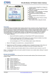
PORT MULTIPLEXER
USER’S
MANUAL
Contents
Preliminary
Manual Revisions
INTRODUCTION
1.1
1.2
1.3
1.4
Purpose of this Manual
Introduction to Port Multiplexer
Port Multiplexer Applications:
Port Multiplexer Specifications
HARDWARE
2.1
2.2
2.3
Dimensional Details and Mounting Instructions
Power Requirements
Communication Ports
Introduction to Port Multiplexer
Port Multiplexer Operation - Configuration and Communication
UNDERSTANDING PORT MULTIPLEXER FEATURES
4.1
4.2
4.3
4.4
Communication Parameters
Status LEDs
Project Setup
Example: Project Settings
CONFIGURATION SOFTWARE
5.1
5.2
System Requirements:
Installation Instructions:
CABLE DIAGRAMS
6.1
Wiring Diagrams
COMMUNICATION CABLES FOR PMUX-00
6.2.1
6.2.2
6.2.3
6.2.4
6.2.5
6.2.6
6.2.7
6.2.8
2
2
3
4
5
GETTING STARTED
3.1
3.2
i
ii
1
AROMAT FP0/FPM TO PMX-00
AROMAT FP1 TO PMUX-00
AROMAT FP2 TO PMUX-00
MODICON MICRO-CONTROLLER TO PMUX-00
OMRON CQM1 PLC TO PMUX-00
IDEC MICRO3 TO PMUX-00
AB SLC DF1 PORT TO PMUX-00
AB MICROLOGIX SERIES PLCs TO PMUX-00
6
8
9
10
11
11
13
14
14
15
15
18
19
19
20
21
22
23
24
25
26
27
28
29
30
IBM CABLES 31
6.2.7 IBM CABLE FOR PMUX-00(IBM 0909-1-00)
TROUBLESHOOTING GUIDE
INDEX
32
33
III
Preliminary
Thank you for purchasing Port Multiplexer product.
This manual will help you to safely install, configure and operate Port Multiplexer Product.
All the safety warnings and precautions must be followed to ensure proper unit performance and personal
safety.
Warnings used in this manual:
DANGER
Danger Warnings are used to indicate situations, locations and
conditions that can cause serious injury or death.
CAUTION
!
Caution Warnings are used to indicate situations and conditions that
can cause operator injury and/or unit damage
IMPORTANT
Port Multiplexer is a Gateway series product, intended to be multiplexing device
that allows two Master devices to transfer the data to slave device having one
communication port on time sharing basis. It is assumed that the user is well
acquainted with the PLCs / Inverters / Controllers / HMI’s being used.
Any mechanical or electrical modification to the unit will void all warranties.
i
Manual Revisions
If you contact us in reference to this manual, please include the following name and revision number
Name: Port Multiplexer User’s Manual
Revision: UMAN\PMUX\0405
Rev. 3
Rev. changed from 0 to 1: Pin details for RJ45 connector revised on page 9
Rev. changed from 1 to 2: Bitmaps changed on page 17
Rev. changed from 2 to 3: AB Micrologix series & AB DF1 Port cables added on page 29 & 30.
We hope that you find this manual informative. If additional information or technical assistance is needed
please contact:
Renu Electronics Private Limited
Survey No. 2/6,
Baner Road, Pune – 411 045
Maharashtra, INDIA
Tel: +91 20 2729 2840
Fax: +91 20 2729 2839
E-mail: [email protected]
Website: www.renuelectronics.com
ii
INTRODUCTION
In this chapter. . . .
Purpose of this Manual
Introduction to Port Multiplexer
Port Multiplexer Applications
Port Multiplexer Specifications
1
1.1
Purpose of this Manual
The intention of this operation manual is to provide a guide for safe installation, configuration and operation of
Port Multiplexer.
Read this operation manual thoroughly before installing and operating Port Multiplexer.
This document is based on information available at the time of its publication. While efforts have been made
to be accurate, the information in this document may not cover all the details or variations in hardware or
software. Features described herein may not be present in all hardwares. Renu Electronics reserves the right
to update information in this publication without prior notice.
1.2
Introduction to Port Multiplexer
The Port Multiplexer is Gateway series product by Renu Electectronics Pvt. Ltd., that behaves little different
than conventional Gateway product (Typical Protocol Converter). It does not convert one protocol to other.
This product has 3 serial ports (2 Master and 1 controller port). On all the communication ports same
protocol is used. We can connect 2 master devices at a time on the Master ports and one (or many) PLC/
Drivers/ controller devices on the controller port. The request/quearies/commands from the Master are
routed to the PLC and the response to those is routed to respective masters. Care is taken that both the
master will be given the same priority. The baud rates and protocols are programmable through the PC
based software. The controller port supports RS232, RS485, and CMOS standards. It is externally powered
(+24 VDC) and has in built Renu Electronics make DC-DC converter.
Configuration of Port Multiplexer:
Each Port Multiplexer has to be configured using Windows based configuration Software before connecting it
to the PLC.
Port Multiplexer
PLC Port
R
OK
PLC
Master 1
Master 2
LR 109782-2
24VDC
+/- 10%
}
Master 1
DC+
DC-
EARTH
PMX-00-B
Master 2
Note:
As Port Multiplexer is a special product from Gateway Series of products, in this manual at some places, user may
see the term “Gateway” instead of Port Multiplexer.
e.g. Gateway Setup Software, which is a common programming software for PMUX as well as other Gateway
products.
2
1.3
Port Multiplexer Applications:
Port Multiplexer connects two master devices to one slave field device having only one communication port,
via serial link. User only needs to configure communication protocol & communication parameters. Port
Multiplexer units have been used in various different applications across many industries. The typical configurations include the followings:
1. HMI and SCADA Communication / PLC Programming to PLC.
Port Multiplexer
Operator interface
X Protocol
2
3
4
5
6
7
8
ESC
0
Master 1
9
+/-
OK
PLC
Master 1
Master 2
PLC Port
1
P ump Mo t o r is O N n o w
S pe ed is 1 4 5 0 RP M
Vo l t s : 4 60 V Cu r r. : 5 A
P r e s s F 5 t o S T OP
ENT
X Protocol
PLC
R
LR 109782-2
A
S
T
R
A
50
RPM
(x10)
0
DC+
DC-
100
}
24VDC
+/- 10%
EARTH
PMX-00-B
X Protocol
Master 2
2. PLC communication with Analog I/O module and Operator Interface
Analog I/O Module
Y Protocol
Master 1
OK
PLC
Master 1
Master 2
PLC Port
EAGLE-0800
Y Protocol
PLC
R
LR 109782-2
DC+
DC-
Operator interface
}
24VDC
+/- 10%
EARTH
PMX-00-B
Motor is Running
Speed : 1450 RPM
F1
F2
NEXT
PREV
F3
F4
F5
Master 2
F6
CLR
Y Protocol
ENT
Port Multiplexer
3. PLC communication with Different Operator Interfaces
Z Protocol
Master 1
1
2
3
4
5
6
7
8
9
ESC
0
+/-
OK
PLC
Master 1
Master 2
PLC Port
P ump Mo t o r is O N n o w
S pe ed is 1 4 5 0 RP M
Vo l t s : 4 60 V Cu r r. : 5 A
P r e s s F 5 t o S T OP
ENT
Operator interface
Z Protocol
PLC
R
LR 109782-2
DC+
DC-
}
24VDC
+/- 10%
EARTH
PMX-00-B
Motor is Running
Speed : 1450 RPM
F1
F2
NEXT
PREV
F3
F4
F5
CLR
Master 2
F6
ENT
Z Protocol
Port Multiplexer
Operator interface
* Images not to scale.
3
1.4
Port Multiplexer Specifications
Power
: + 24 V DC + 10%, 100mA max
LED’s
: 4 LED’s for status indication
Communication Ports : 3 Communication ports
[Isolation between communication ports and Power supply, through DC-DC coupler (isolation = 1 KV)]
PLC Port
: Connects to PLC (RS232/RS485/CMOS)
Master 1
: Connects to Master Device 1 (RS232)
Master 2
: Connects to Master Device 2 (RS232)
Temperature
: Operating : 0o to 50oC
Storage : -20o to 80oC
Humidity
: 10% to 90% (Non condensing)
Mounting
: DIN rail or back panel mounting
Dimensions (DIN rail) : 105mm(L) X 40mm(D) X 51mm(W)
Weight
: 125 gm approx.
Approvals
: CE, CSA
Immunity to ESD
: Level 3 as per IEC1000-4-2
Immunity to Transients: Level 3 as per IEC1000-4-4
Immunity to Radiated RF: Level 3 as per IEC1000-4-3
Immunity to Conducted RF: Level 3 as per IEC1000-4-6
Emissions
: EN55011 CISPRA
4
HARDWARE
In this chapter. . . .
Dimensional Details and Mounting Instructions
Power Requirements
Communications
5
2.1
Dimensional Details and Mounting Instructions
Port Multiplexer unit can be mounted on a back panel or on a DIN rail or can be left hanging. Each Port
Multiplexer unit comes with a separate DIN rail plate when it is packed. User will have to attach the DIN rail
plate to the unit if it has to be mounted on a panel or DIN rail. If it has to be left hanging, make sure to screw
the cables to the DB9 connectors on the Port Multiplexer unit. DIN rail plate also has the provision to screw
the unit to the back panel. Following drawing shows how to attach the DIN rail plate to the unit:
Master 1
PLC Port
Slot for
clamp
DIN rail
clamp
DC+
DCEARTH
OK
PLC
Master 1
Master 2
}
24VDC
+/- 10%
PMX-00-B
Master 2
PMX-00
DIN rail
clip
DIN rail
plate
Following drawing shows the dimensional details of Gateway with DIN rail plate
40
51
Master 1
105
PLC Port
DC+
DCEARTH
OK
PLC
Master 1
Master 2
}
24VDC
+/- 10%
PMX-00-B
Master 2
All dimensions are in mm.
6
Following drawing displays how the unit can be mounted on the DIN rail:
Master 1
EARTH
OK
PLC
Master 1
Master 2
OK
PLC
Master 1
Master 2
PLC Port
PLC Port
DC+
DC-
Master 1
}
DC+
24VDC
+/- 10%
}
24VDC
+/- 10%
DCEARTH
PMX-00-B
PMX-00-B
Master 2
Master 2
Follow instructions given below:
1.
Attach the DIN rail plate to the unit using the clamps on the DIN rail plate.
2.
Pull out the clip of the plate.
3.
Put the unit on the DIN rail.
4.
Push the clip in to secure the unit on the DIN rail.
Following drawing displays how the unit can be mounted on a back panel:
1234567
1234567
Master 1
PLC Port
OK
PLC
Master 1
Master 2
DC+
DCEARTH
}
24VDC
+/- 10%
PMX-00-B
Master 2
1234567
1234567
panel
Follow instructions given below:
1.
Attach the DIN rail plate to the unit using the clamps on the DIN rail plate.
2.
Insert screws in the 4 holes provided on the DIN rail plate.
3.
Tighten the screws to secure the unit in the panel.
7
2.2
Power Requirements
Port Multiplexer is a 24VDC powered unit. Power should be applied on the PCB Terminal block on the Port
Multiplexer unit. Power rating is +24VDC +/- 10%, 100mA max. Please follow the instructions given below
when making power supply connections:
Follow the sticker wiring diagram on the unit which shows terminals for the positive
DC, negative DC and ground.
To make a connection strip about 1/4" (6mm) of insulation of the wire and turn the
connector screw counter-clock wise until the gap is wide open. Insert the wire all
the way in and turn the screw clockwise until it is tight.
Wire lengths should be minimum. Wires should run in pairs with a neutral or
common paired with a live or signal wire.
!
Gateway series products are housed in a molded ABS plastic case which
eliminates any electrical shock hazard. Hence Safety ground is not required to be
connected to the chassis of the unit.
!
The DC ground is not directly coupled to Earth ground internally. The unit is
designed to operate properly whether or not the DC ground is connected to the
Earth ground. We do recommend, however, that if the DC ground has to be
connected to the Earth ground, the Earth connection should be made to a central
star point as poor site earths can introduce noise into a system.
!
Do not power Port Multiplexer and inductive loads with the same power supply even
though there is enough immunity in the Port Multiplexer to withstand the transients
present on these lines. Avoid using power supplies with large capacitive outputs,
which may cause problems if power is cycled within a short time period. If wiring is
to be exposed to lightening or surges, use appropriate surge suppression devices.
Keep AC, high energy and rapidly switching DC wiring separate from signal wires.
Connecting high voltages or AC power mains to the DC input will make Port
Multiplexer unusable and may create an electrical shock hazard to personnel. Such
a failure or shock could result in serious personal injury, loss of life and/or equip
ment damage. DC voltage sources should provide proper isolation from main AC
power and similar hazards.
8
2.3
Communication Ports
Port Multiplexer has two identical communication ports Master1 and Master2 and third port to connect a
PLC. Master ports are compatible to RS232 signal levels and PLC port supports RS232 / RS422 / 2 or 4 wire
RS485 / CMOS signal levels. Pin details are given below:
Master 2
Master 1
5
5
NC
NC
NC
NC
9
9
8
7
6
6
5
4
3
2
1
1
Signal Ground
NC
RXD (RS232C)
TXD (RS232C)
NC
NC
C_CTS
C_RTS
NC
Pin
1
2
3
4
5
6
7
8
6
1
5
4
3
2
1
Signal Ground
NC
RXD (RS232C)
TXD (RS232C)
C_DCD
DB9 Female
DB9 Female
PLC Port
9
9
8
7
6
Signals
RS 232 TXD
RS 232 RXD
GND
TX+
RX+
TXRXCMOS TXD
87654321
User can convert RS485 4 wire + Signal Ground system to a 2 Wire + Signal Ground system by shorting
following signals in the communication cable:
TX+
TXRX+
RXSG
A
B
SG
Note: If user has attached shield to Earth on Device end, leave the shield open on PMUX end. If user
has connected shield to Signal Ground on Device end, connect shield to Signal Ground on PMUX
end.
Upto 31 Devices can be multi-dropped on RS485 port of Port Multiplexer.
9
GETTING STARTED
In this chapter. . . .
Introduction
Gateway Operation - Configuration and Communication
10
3.1
Introduction to Port Multiplexer
Port Multiplexer is a Gateway series product, that allows to transfer the data from two masters on time
sharing basis. It does not convert one protocol to other. This product has 3 serial ports (2 Master and 1
controller port). On all the communication port same protocol is used. We can connect 2 master devices at
a time on the Master ports and one (or many) PLC/Drivers/ controller devices on the controller port. The
request/quarries/commands from the Master are routed to the PLC and the response to those is routed to
respective masters. Care is taken that both the master will be given the same priority. The baud rates and
protocols are programmable through the PC based software. The controller port supports RS232, RS485,
and CMOS standard. It is externally powered (+24 VDC) and has in built Renu Electronics make DC-DC
converter
3.2
Port Multiplexer Operation - Configuration and Communication
PMUX can communicate with any three devices using appropriate cables and configuration. After proper
configuration PMUX allow 2 masters to talk with the slave at the same time. Microsoft Windows based
configuration s/w, Gateway setup configures the PMUX unit. Configuration means making the PMUX unit
work as per the system requirements.
Complete configuration for the PMUX using the Gateway setup is termed as a Project. A Project consists of
communication settings for three ports Master1, Master2 and controller port. It is also possible to set the
time out for the controller port. (This facility depends on the protocol that user has selected.) All the 3
devices have same protocol but they can have the different baud rates and other communication
parameters.
Without any change in the PMUX hardware, PMUX can support many protocols. To communicate with a
device, PMUX needs communication Driver and PMUX – Device communication cable.
Each device has unique and predefined protocol for communication. PMUX driver has this protocol to
communicate with the desired device. As two masters are connected on PMUX, it needs two drivers for the
communication.
User MUST download Project, Master1 driver and Master2 driver in PMUX before installing any
system using PMUX. PMUX can accept drivers and configuration data on Master2 the port. User needs a
special IBM download cable for downloading configuration in PMUX.
If any change in the current / working project is made, user must download the changed project in
PMUX.
Pin details of IBM download cable for PMUX are as follows:
DB9 Male (Port Multiplexer)
2
3
5
DB9 Female (IBM)
2
3
5
IMPORTANT NOTE:
AS PMUX HAS MULTIPLE SIGNALS ON ITS COMMUNICATION PORTS, IBM CABLE FOR
PMUX MUST HAVE ONLY THREE RS232 SIGNALS (TXD, RXD AND GND) AS MENTIONED
ABOVE.
11
IBM download scheme for Port Multiplexer model:
Port Multiplexer needs Firmware, Project and two drivers to communicate with Master1, Master2 and
controller devices. Firmware is factory programmed. If both or one of the drivers has not been downloaded in
Port Multiplexer, it permanently waits for IBM download (indicated by continuous blinking of the OK LED)
Create project as per system requirements. Select Master 1 Driver, Master 2 Driver and Project for downloading. Port Multiplexer can be configured by following method,
1.
2.
3.
4.
If both the drivers are downloaded, at power up Port Multiplexer goes in the IBM download mode, it
flashes the OK LED in that mode. It waits there for approximately 38 sec. If IBM communication is
established on Master 2 port it downloads/ upload the firmware, driver or project or it can do other
function as per the request of set up s/w. If communication is not established from IBM it waits for
valid frame from any of the master. In this state OK LED stops blinking.
Now if it gets the valid frame, it transmits that frame to slave and communication is established.
If no data is received from any of the master for next 15 sec. on the port, it again goes into the IBM
download mode for 20 Seconds, and cycle continues.
If communication is going on and user needs to download any data from the IBM then the user
must disconnect the Master 2 device. Connect the IBM cable to Master 2 port and PC. Wait till the
OK LED starts blinking and then download the data.
Power:
+24VDC + 10%
Communication
Signals
Software will ask user if the Port Multiplexer has to be reset. Port Multiplexer must be reset unless user
wants to download setup again.
IMPORTANT:
1.
When user wants to establish IBM communication on Master2 port, communication on the
other port should not interrupt IBM communication. It is advised that communication on the other
port be stopped to ensure error free IBM communication.
12
UNDERSTANDING PORT MULTIPLEXER FEATURES
In this chapter. . . .
Communication parameters
Status LEDs
Project Setup
Example - Project
13
4.1
Communication Parameters
Communication Parameters of Port Multiplexer can be set from configuration Software. This enables Port
Multiplexer to readily communicate with any device. Communication parameters for MASTER 1, MASTER 2,
and Controller port can be configured independently. This feature allows changes in Baud rate, Number. of
stop bits, Parity etc. at any time without downloading the driver for that particular device. After the driver for a
particular device is downloaded, the communication parameters can be changed simply by selecting new
communication parameters and downloading the same project.
4.2
Status LEDs
Port Multiplexer has 4 status LEDs located near MASTER 1 side. These LEDs indicate communication
status and Gateway operation. Four LEDs are identified as OK, PLC, Master1, and Master2. PLC, Master 1
& Master 2 LEDs indicate communication status on two ports whereas OK LED indicates the Port Multiplexer mode, either configuration or operation.
LED Status
LED Type
OK
ON
OFF
Blink
Controller
Master 1
Master 2
No data transfer
is taking place on
Controller port.
No data transfer
is taking place
on Master 1 port
No data
transfer is
taking place
on Master 2
port.
Data transfer
is taking place
on the Master 1
Master 2 port.
Data transfer
is taking
place on the
If LED is on
continuously then,
Power is ok and
device is ready for
taking the request
from Master 1 and 2
Power is off.
the power supply.
If LED is blinking for Data transfer is
10-15 Sec after taking place on
regular time interval the controller port
then no data is
port.
coming on M1 and
M2 Port & hence
unit is in IBM
communication
mode with standard
gateway software.
14
4.3
Project Setup
This Chapter explains, how a simple Port Multiplexer project can be created and tested. To develop a
PMUX system, select appropriate PMUX model depending on the system requirements. A new project can
be created as follows:
1.
2.
3.
4.
5.
6.
7.
Load Microsoft Windows® based Gateway Setup software.
Select the product Port Multiplexer from the list.
Select the Protocol to be use on all the 3 ports.
Set the communication parameters for the selected protocol.
Apply power to PMUX.
Download the Project and Communication Drivers into PMUX.
Remove Configuration Cable from Master2. Connect Gateway – Master1 and Mater2 cable.
Connect the Controller port cable.
8.
Test system.
Following Port Multiplexer example show detailed setup for common Gateway configurations:
4.4
Example: Project Settings
This project sets the communication parameters and time out for Master 1, Master 2 and Controller.
1. Select the product Port Multiplexer from the list.
Select the Product from the list. (Single Click)
15
2. Select the protocol.
Setup software already has demo projects. To open existing project, user can select “Open Project”
OR can select “Configure” button.
If user is selecting configure button, he should select the protocol first from the list and then, click “Configure”.
3. Opening existing project (for Modbus RTU).
16
Select the required project from the list, shown in the figure. (Sometimes you may need to select appropriate
project folder first and then the actual project).
4. Selecting comminication parameters for Master’s and Controller.
If you have select “Configure” button, then following picture will appear directly:
Select the Master 1, Master 2 OR Controller tab for choosing communication parameters. To choose downloading the firmware, driver OR project, select “Communication” button from “General”.
5. Choosing communication parameters:
Select the appropriate communication parameters for all the ports.
17
CONFIGURATION SOFTWARE
In this chapter. . . .
System Requirements
Installation Instructions
18
5.1
System Requirements:
For configuration Port Multiplexer uses the Gateway Setup software that runs on a PC/AT compatible
computer with the following specifications:
Windows Version
Processor
Hard disk Space
Serial Mouse
RAM
Display resolution
Display colors
5.2
: Microsoft Windows 9x / 2000
: PENTIUM or higher
: 5 MB or more
: Required
: 16 MB or more
: 800 X 600 (VGA) or better
: 16 bit color
Installation Instructions:
Use the following procedure to install the Microsoft Windows® based Gateway setup software This
installation shows the procedure to install the software from a CD Disk on drive E. On machines with different
drive configurations, change the names as needed. It is recommended that a backup disk of the Gateway
setup software disk be created and stored in a safe place.
1.
Launch the Windows operating system.
2.
Insert the setup CD into CD-drive.
3.
Point to the start button then click RUN
4.
In the command line box enter E:\Disk1\setup.exe. Click OK. This will launch the Gateway installer.
5.
Follow the instructions to complete setup.
Gateway Project:
This software is used for all Gateway series products.
Each Port Multiplexer must be configured before connecting it to the PLC. Gateway configuration software
allows the following:
1.
Create a new Port Multiplexer project
Select protocols for all communication ports of Port Multiplexer.
Selecting the time out for controller port. (If necessary & protocol supports)
Set Communication Parameters for all the ports.
2.
Downloading.
Download Project
Download drivers
Download new firmware, if required (only for upgrading).
3.
Upload Project.
The existing project in the Port Multiplexer module can be viewed/edited.
4.
Upload System Data.
This option enables viewing of version number, status of firmware, drivers used, and boot block.
19
CABLE DIAGRAMS
In this chapter. . . .
Wiring Diagrams
Communication Cable
20
6.1
Wiring Diagrams
User must ensure correct wiring for error-free operation of Port Multiplexer. Each device being connected to
PMUX has a unique communication port. Pin outs of communication ports of Port Multiplexer are given in
section 2.3. Port details of the other devices can be found in the device manual.
Port Multiplexer has RS232, RS422, RS485 and CMOS compatible communication ports, so user can
directly connect any device with these communication signals.
This section gives wiring diagrams for connecting Port Multiplexer using various singnal levels.
1.
Network of RS422 / RS485 4 wire + signal ground system
RT
DEVICE 0
RX+
RXTX+
TXGND
DEVICE 1
RX+
RXTX+
TXGND
Power: +24VDC +
RT
RX+
RXTX+
TXGND
RX+
RXTX+
TXGND
DEVICE 2
RX+
RXTX+
TXGND
Note:
User should add Termination resistor (RT=180 Ohm ) in Receive lines of first and last node.
2.
Network of RS485 2 wire + signal ground system
DEVICE 0
A (+ve)
B (-ve)
GND
DEVICE 1
A (+ve)
B (-ve)
GND
Power: +24VDC +
DEVICE 2
RX+
RXTX+
TXGND
21
A (+ve)
B (-ve)
GND
A (+ve)
B (-ve)
GND
COMMUNICATION CABLES FOR PMUX-00
22
6.2.1
AROMAT FP0/FPM TO PMX-00
AROMAT FP0
SIDE
PMUX SIDE
2 mtr.
MINIDIN 5 PIN MALE
(RS232)
8P8C MALE
(RS232)
Shield Wire
SIGNALS
Pin #
Pin #
SIGNALS
SG
1
1
RS 232 TX
TXD
2
2
RS 232 RX
RXD
3
3
GND
4
4
5
5
6
7
8
Shield Wire
5 PIN MINIDIN CONNECTOR
PINOUTS
8 PIN MODULAR CONNECTOR
PINOUTS
R.H.S. VIEW
FRONT VIEW
4
5
2
Pin 1
(Left side)
3
Pin 8
1
Cable insert end
23
Cable insert end
6.2.2
AROMAT FP1 TO PMUX-00
ARPMAT FP1
SIDE
GWY-00 SIDE
2 mtr.
DIN CONNECTOR MALE
(RS485)
8P8C MALE
(RS232)
Shield Wire
SIGNALS
Pin #
Pin #
SG
1
1
TX-
2
2
RX-
3
3
GND
4
4
TX+
TX+
5
5
RX+
RX+
6
6
TX-
7
7
RX-
8
8
SIGNALS
Shield Wire
DIN CONNECTOR
PINOUTS
8 PIN MODULAR CONNECTOR
PINOUTS
2
1
3
5
7
R.H.S. VIEW
FRONT VIEW
4
Pin 1
(Left side)
Pin 8
6
Cable insert end
8
24
Cable insert end
6.2.3
AROMAT FP2 TO PMUX-00
AROMAT FP2 SIDE
PMUX-00 SIDE
ATTACH
PLC
2 mtr.
DB9 MALE
(RS232)
8P8C MALE
(RS232)
Shield Wire
Pin #
Pin #
SIGNALS
1
1
RS 232 TX
TXD
2
2
RS 232 RX
RXD
3
3
GND
4
4
5
5
6
6
7
7
8
8
SIGNALS
SG
9
Shield Wire to DB9 body
DB9 MALE
PINOUTS
8 PIN MODULAR CONNECTOR
PINOUTS
R.H.S. VIEW
FRONT VIEW
Pin 1
(Left side)
6
9
Pin 8
1
5
Cable insert end
25
Cable insert end
6.2.4
MODICON MICRO-CONTROLLER TO PMUX-00
PMUX-00 SIDE
MODICON CONTROLLER
SIDE
2 mtr.
8 PIN MODULAR
CONNECTOR (RS232)
SIGNALS
8P8C MALE
(RS232)
Shield Wire
Pin #
Pin #
SIGNALS
1
RS 232 TX
2
RS 232 RX
3
GND
1
2
TXD
3
RXD
4
SG
5
4
5
6
6
7
7
EARTH
8
8
8 PIN MODULAR CONNECTOR
PINOUTS
Shield Wire
R.H.S. VIEW
FRONT VIEW
Pin 1
(Left side)
Cable insert
end
Pin 8
(Right side)
Cable insert
end
26
6.2.5
OMRON CQM1 PLC TO PMUX-00
PMUX-00 SIDE
OMRON CQM1
SIDE
ATTACH
PLC
2 mtr.
8P8C MALE
(RS232)
DB9 MALE
(RS232)
Shield Wire
SIGNALS
Pin #
EARTH
1
TXD
2
RXD
3
Pin #
SIGNALS
1
RS 232 TX
2
RS 232 RX
3
GND
4
4
5
5
6
6
7
7
8
8
SG
9
DB9 MALE
PINOUTS
Shield Wire
8 PIN MODULAR CONNECTOR
PINOUTS
R.H.S. VIEW
FRONT VIEW
Pin 1
(Left side)
6
9
Pin 8
1
5
Cable insert end
27
Cable insert end
IDEC MICRO3 TO PMUX-00
6.2.6
PMUX-00 SIDE
IDEC MICRO3
SIDE
2 mtr.
MINIDIN 8 PIN MALE
(RS232)
8P8C MALE
(RS232)
Shield Wire
SIGNALS
Pin #
Pin #
A
1
1
B
2
2
3
3
GND
4
TX+
5
RX+
6
TX-
7
7
RX-
8
8
4
A
5
B
6
SG
Shield Wire
8 PIN MINIDIN CONNECTOR
PINOUTS
6
3
8 PIN MODULAR CONNECTOR
PINOUTS
8
7
5
R.H.S. VIEW
FRONT VIEW
Pin 1
(Left side)
4
1
SIGNALS
Pin 8
2
Cable insert end
28
Cable insert end
6.2.7
AB SLC DF1 PORT TO PMUX-00
PMUX-00 SIDE
AB SLC SIDE
ATTACH
PLC
2 mtr.
8P8C MALE
(RS232)
DB9 FEMALE
(RS232)
SIGNALS
Shield Wire
Pin #
SIGNALS
1
RS 232 TX
2
RS 232 RX
3
GND
Pin #
1
RXD
2
TXD
3
4
4
5
SG
5
6
6
7
7
8
8
9
DB9 FEMALE
PINOUTS
Shield Wire to DB9 body
8 PIN MODULAR CONNECTOR
PINOUTS
R.H.S. VIEW
FRONT VIEW
Pin 1
(Left side)
9
6
Pin 8
5
1
Cable insert end
29
Cable insert end
6.2.8
AB MICROLOGIX SERIES PLCs TO PMUX-00
PMUX-00 SIDE
AB MICROLOGIX
SIDE
2 mtr.
MINIDIN 8 PIN MALE
(RS232)
SIGNALS
SG
RXD
TXD
Pin #
Pin #
SIGNALS
1
1
RS 232 TX
2
2
RS 232 RX
3
3
GND
4
4
5
5
6
6
7
7
8
8
Shield Wire
8 PIN MINIDIN CONNECTOR
PINOUTS
6
3
8 PIN MODULAR CONNECTOR
PINOUTS
8
7
5
R.H.S. VIEW
FRONT VIEW
Pin 1
(Left side)
4
1
8P8C MALE
(RS232)
Shield Wire
Pin 8
2
Cable insert end
30
Cable insert end
IBM CABLES
31
IBM CABLE FOR PMUX-00(IBM 0909-1-00)
PC SIDE
PMUX-00 SIDE
2 mtr.
UNIT
IBM
6.2.7
DB9 FEMALE
(RS232)
DB9 MALE
(RS232)
Shield Wire
Pin #
Pin #
1
1
RXD
2
2
TXD
TXD
3
3
RXD
4
4
5
5
6
6
7
7
8
8
9
9
SIGNALS
SG
DB9 FEMALE
PINOUTS
9
Shield Wire
SIGNALS
SG
DB9 MALE
PINOUTS
5
6
6
1
9
1
5
32
TROUBLESHOOTING GUIDE
33
Trouble-shooting Guide
LED Indicators
Port Multiplexer has 4 status LEDs located near Master1 side. These LEDs indicate communication status
and Gateway operation. Four LEDs are identified as OK, PLC, Master1, and Master2. PLC, Master1 &
Master2 LEDs indicate communication status on two ports whereas OK LED indicates the Port Multiplexer
mode, either configuration or operation.
LED Status
LED Type
OK
ON
OFF
Blink
Controller
Master 1
Master 2
No data transfer
is taking place on
Controller port.
No data transfer
is taking place
on Master 1 port
No data
transfer is
taking place
on Master 2
port.
Data transfer
is taking place
on the Master 1
Master 2 port.
Data transfer
is taking
place on the
If LED is on
continuously then,
Power is ok and
device is ready for
taking the request
from Master 1 and 2
Power is off.
the power supply.
If LED is blinking for Data transfer is
10-15 Sec after taking place on
regular time interval the controller port
then no data is
port.
coming on M1 and
M2 Port & hence
unit is in IBM
communication
mode with standard
gateway software.
Some more Important details of the LED status behaviour of the unit:
1)
What unit does on Power on: a)
The OK LED starts blinking. It blinks for 38 Sec (approx.). This time unit is in the IBM
download mode. It tries to communicate with the Gateway software.
b)
If no attached frame comes from the IBM PC during this time, the unit waits for the valid
frames coming from the Master1 or Master2. At this moment of time OK LED does not
blink, it glows continuously for 15 Seconds.
c)
Again if for those 15 Sec if no bytes comes from any of the Master1 and Master2 port the
unit goes in the IBM download mode for next 16 Sec and cycle repeats.
If user needs to download/upload any data from the Gateway software he/she must wait till
OK LED flashes i.e. units goes in the IBM download mode. In this mode only Gateway
software can communicate with unit. If user tries to do when OK LED is continuously on
then time out error will occur in the Gateway software.
IBM Download:
While downloading into the unit, user must make sure that the “OK” LED is blinking and not steady. If user
selects download OR upload while “OK” LED is steady, timeout error will occure in the software.
34
INDEX
III