1
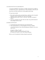
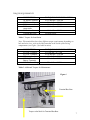
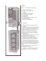
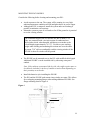
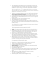
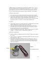
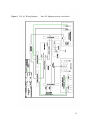
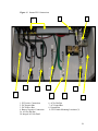
OutBack
Power
Systems
PS1 Grid-Tie
with Battery
Backup
Installation
Instructions
and User
Guide
1
The OutBack Power Systems PS1 Grid-Tie with Battery Backup is a complete power
conversion center designed to meet UL, CSA, NEC and IEEE standards. The PS1 is
assembled from UL, ETL and CSA listed components, all factory-wired and tested for
integrated operation and performance.
Please read all the component manuals included with the PS1. OutBack Power Systems
highly recommends the use of an OutBack MATE (sold separately) for monitoring and
programming your PS1 system.
About OutBack Power Systems
OutBack Power Systems is a leader in advanced energy conversion technology. Our
products include inverter/chargers, charge controllers, auto-transformers, system
communication components, as well as battery temperature sensors, breaker panels,
breakers, and assembled systems.
Notice of Copyright
OutBack Power Systems PS1 Grid-Tie with Battery Backup Installation Instructions and
User Guide. All rights reserved.
Disclaimer
UNLESS SPECIFICALLY AGREED TO IN WRITING, OUTBACK POWER
SYSTEMS:
(a) MAKES NO WARRANTY AS TO THE ACCURACY, SUFFICIENCY OR
SUITABILITY OF ANY TECHNICAL OR OTHER INFORMATION PROVIDED IN
ITS MANUALS OR OTHER DOCUMENTATION.
(b) ASSUMES NO RESPONSIBILITY OR LIABILITY FOR LOSS OR DAMAGE,
WHETHER DIRECT, INDIRECT, CONSEQUENTIAL OR INCIDENTAL, WHICH
MIGHT ARISE OUT OF THE USE OF SUCH INFORMATION. THE USE OF ANY
SUCH INFORMATION WILL BE ENTIRELY AT THE USER’S RISK.
Date and Revision
June 22, 2006
Contact Information
OutBack Power Systems
19009 62nd Ave. NE
Arlington, WA 98223
Phone (360)435-6030
Fax (360)435-6019
www.outbackpower.com
PS1 Grid-Tie with Battery Backup Installation Instructions and User Guide 6/22/2006
Copyright 2006 OutBack Power Systems, Inc.
Rev 1.0 Prlim-900-0048-1
2
Warranty Summary
Dear OutBack Customer,
Thank you for your purchase of OutBack products. We
make every effort to assure our power conversion products
will give you long and reliable service for your renewable
energy system.
As with any manufactured device, repairs might be needed
due to damage, inappropriate use, or unintentional defect.
Please note the following guidelines regarding warranty
service of OutBack products:
•
Any and all warranty repairs must conform to the terms
of the warranty.
•
All OutBack equipment must be installed according to
their accompanying instructions and manuals with
approved over-current protection in order to maintain
their warranties.
•
The customer must return the component(s) to
OutBack, securely packaged, properly addressed, and
shipping paid. We recommend insuring your package
when shipping. Packages that are not securely packaged
can sustain additional damage not covered by the
warranty or can void warranty repairs.
•
There is no allowance or reimbursement for an
installer’s or user’s labor or travel time required to
disconnect, service, or reinstall the damaged
component(s).
•
OutBack will ship the repaired or replacement
component(s) prepaid to addresses in the continental
United States, where applicable. Shipments outside the
U.S. will be sent freight collect.
•
In the event a product malfunction, OutBack cannot
bear any responsibility for consequential losses,
expenses, or damage to other components.
•
Please read the full warranty at the end of this manual
for more information.
3
Scope
The manual provides safety guidelines and installation information. It does not
provide information about specific brands of solar panels and supplies limited
information on batteries.
TABLE OF CONTENTS
Read First
Important Safety Instructions
Regulatory Compliance
Factors Affecting PS1 Performance
General Maintenance
Torque Requirements
Features
Battery Precautions
Additional Notices
Grounding Notices
List of Included Items
Additional Equipment, Tools and Parts Required
Mounting the Enclosures
Battery Selection and Installation
Battery Selection
Suggested Batteries
PS1-BE Battery Installation
Testing the Battery Installation
AC Connections
AC Output
External Sub-panels
AC Input
Lightning Arrestors
Internal PS1 Connections
PV Wiring Instructions
Using the PS1’s Integral PV Combiner Area
Using the External PSPV Combiner Box
DC Wiring Instructions
AC Wiring Instructions
Installing the MATE Remote Status Display
Operation
Power Usage
DC Ground Fault Detector/Interrupter
Utility Connection and Inspection
Warranty
5
5
5
6
6
7
8
9
10
10
10
11
14
16
16
16
17
18
20
20
22
22
22
25
25
26
27
28
29
33
33
33
34
35
36
4
READ FIRST
Please read pages 5-12 before installing the PS1.
IMPORTANT: READ AND SAVE THESE SAFETY INSTRUCTIONS
This manual contains important instructions to follow during the installation and
maintenance of the OutBack Power Systems PS1 Grid-Tie with Battery Backup
system.
1. Read all instructions and cautionary markings on the PS1, the batteries
and all appropriate sections of this installation and user manual as well as
included manuals for other components before using the system.
2. Install all components and wiring according to national and local
electrical and building codes. This includes, but is not limited to,
submitting a plan to the local building department, passing inspection, and
requiring a licensed electrician to do the work when mandated. OutBack
Power Systems cannot be responsible for system failure, damages, or
injury resulting from improper installation of their products.
3. Use only the recommended wire sizes or greater. Be sure all wires are in
good condition.
4. Avoid damaging the PS1 or its components prior to or during
installation. Do not install damaged units.
5. To reduce the risk of electrical shock, disconnect AC, DC, and PV
power from the PS1 before cleaning or doing any maintenance work.
Turning off the PS1 alone may not eliminate this risk. Solar modules can
produce hazardous voltages when exposed to light. Cover them with
opaque material before servicing any connected equipment.
6. The PS1 must be properly grounded for safe operation.
7. Do not disassemble the PS1; refer all servicing to qualified service
personnel. Incorrect re-assembly risks electric shock or fire.
REGULATORY COMPLIANCE
The PS1 has been ETL tested to UL standard 1741 and is also CSA certified to C22.2 No.
107.1—01. ETL is a Nationally Recognized Testing Laboratory (NRTL).
5
FACTORS AFFECTING PS1 PERFORMANCE
A correctly installed PS1 will perform in accordance with the power available to
it, whether from a grid or a renewable source. This performance is affected by PV
array factors and certain inefficiencies in the equipment and wiring.
PV array factors include:
•
•
•
Real world conditions rarely meet ideal factory conditions used to rate panels.
Typically, an array will produce 60-70% of its rated output.
High temperatures reduce an array’s efficiency, especially roof-mounted
systems.
The array’s orientation, the angle of the sun, shade, smog, and the amount of
daily sunlight all affect results.
GENERAL MAINTENANCE
•
•
Occasionally inspect the PS1 for loose wires and connections.
When replacing batteries in a PS1-BE (Battery Enclosure), OutBack
recommends using four of one of the following types of batteries. Do not mix
battery types!
` Trojan 31-AGM or 27-AGM
` MK 8A31 or 8A27 (AGM) or 8G31or 8G27 (Gel)
` Concorde PVX-1080T or PVX-1040T (both AGM type)
Refer to your local regulations for battery disposal requirements.
6
TORQUE REQUIREMENTS
CONNECTION
AC and PV breakers
GFP/2 assembly
DC shunt
DC battery
connections
DC Positive Bus
Terminal Bus Bars
TORQUE IN POUND MEASURES
to 22 inch-lbs = 2.48 Nm
to 30 inch-lbs = 3.39 Nm
to 10 foot-lbs = 13.6 Nm
to 10 foot-lbs = 13.6 Nm
to 10 foot-lbs = 13.6 Nm
See note below
Table 1 Torques for Installation
Note: The terminal bus bars have different torque requirements depending on
hole and wire sizes; refer to the label attached to the inside of the wiring
compartment (see Figure 1 for label location).
CONNECTION
FX’s DC Terminals
FX’s AC Terminals
FX battery breaker
MX60’s PV and
Battery Terminals
MX60’s Ground Lug
TORQUE IN POUND MEASURES
to 5 foot-lbs = 6.77 Nm
to 30 inch-lbs = 3.38 Nm
to 45 inch-lbs = 5.08 Nm
to 35 inch lbs = 3.95 Nm
to 35 inch lbs = 3.95 Nm
Table 2 Additional Torques for Maintenance
Figure 1
Terminal Bus Bars
Torque value label for Terminal Bus Bars
7
Figure 2
FigureD1
PS1 as seen through its metal enclosure.
E
A
A: upper enclosure (PS1)
B: battery enclosure (PS1-BE)
C: conduit
D: FX Series Inverter/Charger
E: MX60 Charge Controller
F: breaker panel
G: battery bank
H: GFCI breaker and weatherproof cover
(supplied by installer)
I. PS1’s wiring compartment
F
H
I
C
B
G
FEATURES
• This is a single phase system with a sinewave output.
• The PS1 is approved for outdoor mounting
(TYPE 3R) only in the vertical position. All
wiring to and from the PS1 enclosures must be
suitable for rain tight or wet locations in
compliance with UL514B. The conduit hub
connecting to the PS1 must have a TYPE 3R
waterproof rating.
• The PS1 includes one FX Inverter/Charger,
one MX60 Charge Controller, and
accommodates two weatherproof GFCIs.
• PV panels (up to 2700 W for PS1-2500 or
3200 W for PS1-3000) connect to the PS1.
• When the grid is connected, the PS1 can
provide power to the backed-up loads and sell
power to the utility. When the grid fails, the PS1
will power backed-up loads utilizing battery
power.
• Mounting holes are 16” apart to secure to
standardized stud spacing.
• OutBack pre-wires the PS1 to save onsite
installation time, materials, and difficulties.
8
BATTERY PRECAUTIONS
WARNING - WORKING IN THE VICINITY OF LEAD ACID
BATTERIES IS DANGEROUS. NON-SEALED BATTERIES GENERATE
EXPLOSIVE GASES DURING NORMAL OPERATION. Provide ventilation to
the outdoors from the battery compartment. The battery enclosure should be designed
to prevent accumulation and concentration of hydrogen gas in “pockets” at the top of
the enclosure. Vent the battery compartment from the highest point if using a battery
enclosure other than the PS1-BE. A sloped lid can be used to direct the flow of
hydrogen to the vent opening at the highest possible location.
CAUTION - To reduce risk of injury, charge only deep-cycle lead acid, lead
antimony, lead calcium, gel cell or absorbed glass mat type rechargeable batteries.
Other types of batteries may burst, causing personal injury and damage. Never charge
a frozen battery.
PERSONAL PRECAUTIONS
•
•
•
•
•
•
•
•
Someone should be within range of your voice to come to your aid if needed.
Have plenty of fresh water and soap nearby in case battery acid contacts skin,
clothing, or eyes.
Wear complete eye protection. Avoid touching eyes while working near
batteries. Wash your hands with soap and warm water when done.
If battery acid contacts skin or clothing, wash immediately with soap and
water. If acid enters eye, flood eye with running cool water at once for at least
15 minutes and then get medical attention immediately.
Keep a supply of baking soda on hand to neutralize lead acid battery
electrolyte.
NEVER smoke or allow a spark or flame in vicinity of a battery or generator.
Be extra cautious to reduce the risk of dropping a metal tool onto batteries. It
could short-circuit the batteries or other electrical parts that may result in fire
or explosion.
Remove personal metal items such as rings, bracelets, necklaces, and watches
when working with a battery. A battery can produce a short circuit current
high enough to weld a ring or the like to metal, causing severe burns.
9
ADDITIONAL NOTICES
•
•
•
•
For instructions on mounting, see the MOUNTING THE ENCLOSURES
section of this manual.
For battery installation and maintenance, read the battery manufacturer's
instructions prior to installation and operation. See the BATTERY
SELECTION AND INSTALLATION section for more information.
All installations must comply with local and national electrical codes and
standards.
If a remote or automatic generator start system is used, disable the automatic
starting circuit and/or disconnect the generator from its starting battery to
prevent starting during installation or servicing.
GROUNDING NOTICES
•
•
•
•
This product’s intended installation is as part of a permanently grounded
electrical system per the National Electrical Code (NEC). The equipment
ground on the PS1 is marked “GROUND BUS” and is located inside the
PS1’s Wiring Compartment.
In the electrical system, the AC Neutral conductor must be grounded to a
single point only. This bonding should already be present at the main service
entrance panel.
The negative battery conductor must be grounded to only a single point in the
system. This bonding is already achieved through the pre-wired OBDCGFP/2 inside the PS1.
Never positive ground the PS1.
LIST OF INCLUDED ITEMS
1. PS1-2500 or PS1-3000
Ventilated rainproof aluminum enclosure with the following equipment:
•
•
•
•
•
•
•
•
•
•
•
•
GTFX3048 (PS1-2500) or the GVFX3648 (PS1-3000) inverter/charger
MX60 PV MPPT charge controller
HUB4 communications manager
thermally actuated cooling fan
50 amp AC bypass breaker (UL1077)
50 amp AC output breaker (UL1077)
50 amp AC input breaker (UL1077)
one 20 amp and one 15 amp branch-circuit-rated load circuit breakers (UL489)
and space for two more
eight breaker spaces for use as an internal PV combiner
OBDC-GFP/2 ground fault protector, PV disconnect & MX60 battery disconnect
(triple-ganged UL489)
125 amp 125 VDC FX circuit breaker, 25,000 AIC (UL489)
500 amp 50mv shunt for external meter monitoring (external meter not included)
10
•
•
•
•
•
•
•
•
AC IN HOT, AC OUT HOT, AC NEUTRAL, GROUND and DC NEGATIVE
terminal bus bars
knockouts for side and bottom conduit entry
lockable flip-up circuit breaker cover
1/4” thick polycarbonate viewing window
two RTS battery temperature sensors
50 foot CAT 5 cable for remote monitoring through the optional MATE or
MATE2
AC and DC lightning arrestors
fingered bus connector to combine PV strings
2. PS1-BE (Battery Enclosure)
Note: The PS1 Battery Enclosure (PS1-BE) is sold separately from the PS1.
Ventilated rainproof aluminum enclosure with the following equipment:
•
•
•
•
•
•
shelves to hold four group 27 or group 31 sealed (required) AGM or gel batteries
placed on their side
battery hold-down straps
1/0 flexible MTW2 cable for battery positive, battery negative and battery
interconnects
one 1/4” x 6” rigid conduit nipple and two waterproof TYPE 3R conduit hubs
(also called Myers hubs) to connect the PS1 directly over the PS1-BE
knockouts on top and each side for connection to the PS1 or additional PS1-BEs
lockable front cover plate
Note: Each PS1-BE stores 4800 watt hours of power when using group 31 size batteries
and slightly less for group 27 size batteries.
ADDITIONAL EQUIPMENT, TOOLS, AND PARTS REQUIRED
Equipment:
•
•
•
•
•
•
48-72VDC nominal PV array (up to 2700 W for the PS1-2500 and 3200 W for
the PS1-3000)
PV combiner if not using the integral combiner slots in the PS1
one OBPV breaker for every PV string when using the integral PV combiner
mounts and wiring for the PV array
48V nominal battery bank
lockable and visible AC disconnect (not an NEC or UL requirement, but may be
required by the utility company)
Note: In accordance with the National Electrical Code, ANSI/NFPA 7, a 60 amp branch
circuit rated breaker offering AC branch circuit over-current protection for the PS1’s AC
input must be used in the main service entrance panel.
11
Your utility might require a separate AC input meter for monitoring power
production.
X To fully monitor PV production sold to the grid and sent downstream to house
loads, install two separate meters—one on the AC Input to the PS1 and one on the
AC Output to the PS1.
X Install a “Form 12S” meter to monitor all power produced. A “Form 12 S”
meter can be used for “Green Tag” programs. See the setup at
www.outbackpower.com/technicalnotes.htm
X
Tools Required for Installation:
•
•
•
•
•
•
•
•
•
flathead screwdriver (torque measuring recommended)
Phillips screwdriver (torque measuring recommended)
ratchet (torque measuring recommended) with 1/2” and 9/16” attachments
drill and 3/16” bit
hammer
1/2” wrench
wire stripper
stud finder
carpenter’s level
Additional Parts Required:
•
•
•
four 16d finish nails
six or more 5/16” X 2 1/2” lag bolts per PS1 and PS1-BE with 5/16” washers
and nuts for each lag bolt
one 1/4” ring terminal to connect the PV positive wire to the OBDC-GFP/2
inside the PS1 (ring terminal must fit the gauge of the PV positive wire)
12
Figure 3
Note: The center of the viewing window is 5’2” from the bottom of the PS1-BE.
cabinet
VIEWING
WINDOW
13
MOUNTING THE ENCLOSURES
Consider the following before locating and mounting your PS1:
•
•
•
Avoid exposure to the sun. The system will be running in a very high
ambient temperature condition and full sunlight reduces its power output.
Although the PS1 is rainproof, install the system under an overhang if
possible to minimize rain exposure.
Mount the system to posts or wall studs as far off the ground as is practical
to see the viewing window.
The combined height of the PS1 and the PS1-BE is about 67 1/2”.
They are connected with a six-inch section of conduit and two
Myers hubs which, when threaded, add about seven inches to the
overall height (approximately 74 1/2”). Use this as your working
height when locating and mounting the sections one over the other.
A person 5’10” tall can comfortably read the viewing window if the
PS1-BE is about five inches off the ground.
•
The PS1-BE can be mounted next to the PS1 with modified cable length.
Additional PS1-BE’s can be installed side by side using waterproof
conduit.
Note: If the cabinets are mounted side-by-side, they might require more or
less than the included six inches of conduit to connect them depending on
their proximity to each other.
•
•
Install the batteries after installing the PS1-BE.
The PS1 and the PS1-BE each mount sixteen inches on center. This allows
for overlapping mounting flanges when adding additional PS1-BEs. See
flange mounting detail in Figure 4.
Figure 4
SHEATHING
14
•
After establishing the height and placement, use the stud finder to locate the wall
studs and mount the PS1 first. This cabinet weighs approximately 107 pounds and
OutBack Power Systems strongly recommends two people handle its installation.
Note: Use at least six 5/16” x 2 1/2” lag bolts and flat washers to secure both the
PS1 and PS1-BE to the wall studs. OutBack Power Systems cannot be responsible for
damage done to an improperly secured system.
•
•
•
•
•
•
The PS1 has 16 openings for fasteners to secure it to a wall. Determine the location
of two of these (on the same level) and hammer two 16d finish nails at least 2 1/2”
into the wall studs. Check that they are level.
Carefully lift and temporarily hang the PS1 on these nails and verify the PS1 is level.
Drill pilot holes (top, middle, and bottom) for six (or more) 5/16” X 2 1/2” lag bolts
using a 3/16” bit.
Install the lag bolts, washers, and nuts and tighten securely.
The 16d finish nails can be removed, if desired.
For battery enclosures other than the PS1-BE, connect the battery enclosure to the
PS1 at this time with approved conduit for this installation; do not install and connect
the battery bank yet.
Note: OutBack does not recommend installing the PS1 without some form of battery
enclosure connected with conduit.
The following installation instructions apply to the PS1-BE:
•
•
•
•
•
The PS1-BE weighs approximately 29 pounds and is more easily installed by two
people.
Install both Myers hubs on the six-inch conduit and remove the locknuts from the
outside ends. Tighten both Myers hubs so the overall length is 8 3/4” end to end.
Remove the 1 3/4” diameter knockout on the bottom of the PS1.
From the outside of the upper cabinet, push one end of the conduit along with the
Myers hub through the knockout hole. Replace the locknut, tightening it enough to
stay attached, but leave the hub loose until the battery enclosure is installed.
Hold a carpenter’s level or carpenter’s square to the lower sections of each side of
the PS1 and draw pencil lines down the wall. These will act as guides for lining up
the PS1-BE. Verify the studs’ location with the stud finder.
For mounting the PS1-BE under the PS1 cabinet:
•
•
•
•
•
•
•
•
•
Remove the 1 3/4” diameter knockout on the upper surface of the PS1-BE.
The PS1-BE will hang approximately 7” under the PS1 cabinet.
Confirm the conduit knockout is aimed upward.
Hold the PS1-BE to the wall and move it upward so the conduit slips through the
PS1-BE’s knockout.
Line up the PS1-BE with the pencil lines.
Check that the PS1-BE is level.
Hammer a 16d nail through one of the fastener openings on each side of the PS1-BE
so it can temporarily hang on them, checking again that the cabinet is level and
square.
Drill pilot holes (top, middle, and bottom) for at least six (or more)
5/16” X 2 1/2” lag bolts using a 3/16” bit.
Install the lag bolts, washers, and nuts and tighten securely.
15
•
•
Remove the 16d finish nails, if desired.
Replace the locknut on the Myers hub in the PS1-BE. Tighten both lock nuts
inside each cabinet until the conduit is secure.
BATTERY SELECTION AND INSTALLATION
The PS1 requires a 48V battery bank with at least 100 amp-hours (20 hour rate) of battery
capacity. The battery bank capacity of a PS1-2500 should not exceed 700 amp hours and
the PS1-3000 should not exceed 900 amp hours. When using a battery enclosure other
than the PS1-BE, be sure the enclosure is vented if using vented batteries. The positive
and negative battery cables should run together and travel as short a distance as possible.
BATTERY SELECTION
The PS1-BE is meant to use sealed gel or AGM batteries only. OutBack Power Systems
has worked with three battery manufactures to ensure the PS1 system will give the best
battery-backed grid-tie inverter system performance. Concorde, MK, and Trojan all make
group 27 or group 31 AGM batteries that are ideal for just this application. These
manufactures are well known in the renewable energy (RE) industry. A 48V nominal
battery bank is required whether a PS1-BE is used or not.
Only use batteries built for RE applications. Other types, such as automobile batteries, are
not suitable. OutBack Power Systems believes properly maintained batteries can last a
good ten years in a PS1 application.
SUGGESTED BATTERIES:
•
•
•
Trojan 31-AGM or 27-AGM
MK 8A31 or 8A27 (AGM) or 8G31or 8G27 (Gel)
Concorde PVX-1080T or PVX-1040T (AGM)
The PS1’s battery voltage set point for selling power back to the grid is 52 VDC. This
means any excess RE beyond what is required to maintain the 52 VDC charge is sold.
The system’s energy demands along with normal energy losses from the batteries will
cause a drop in the battery voltage, thus a small amount of energy is required to maintain
the 52 VDC charge even when the battery is not supplying power to other loads.
OutBack testing with sealed AGM batteries, for example, shows it takes about 10 watts to
keep four group 31 batteries at the sell voltage during sunlight hours. Ten watts is a
minor use of RE given the benefits of battery back-up.
The PS1-BE comes with everything needed to install and hook up the batteries except the
batteries themselves:
•
•
•
•
four battery straps to secure the batteries
three 21” 1/0 battery cables to connect the batteries in series
one 39” 1/0 battery cable to connect the battery positive to the PS1’s DC
Positive bus
one 49” 1/0 battery cable to connect the battery negative to the PS1’s DC shunt
(negative bus)
16
PS1-BE BATTERY INSTALLATION
X Batteries are a live power source. Be cautious when connecting cables.
X Refer to the Table 1 Torque Requirements for the DC battery, DC shunt, and DC
Positive Bus connections.
•
•
•
•
•
•
•
Install the sealed batteries on their sides with the PLUS (positive) terminal on the
left side as shown in the Figure 6.
Secure the batteries with the battery straps.
Run both Remote Temperature Sensors (RTS) through the conduit now before
the battery cables are installed. Attach each RTS to the surface of the same
battery (any battery is acceptable).
Use the three 21” cables supplied to make the three series interconnects (see
Figure 6).
With the FX battery breaker off (see #4 in Figure 7), connect the 39” red cable
with red ends to the top battery’s PLUS terminal, run the cable through the
conduit, and connect the other end to the DC Positive Bus in the PS1 (see #3
Figure 10) using the hardware supplied and a 1/2” wrench and socket. The
battery cable lug must contact the bus bar.
Wrap the bottom lug of the 49” black cable with black ends with several layers of
electrical tape to prevent it from accidentally shorting out against the battery.
Connect the top end of this cable to the left side of the DC shunt inside the PS1
(see Figure 10, location #4, “Battery Negative Connection”). Run this cable
through the conduit to the battery enclosure. Carefully remove the tape from the
bottom end of the battery negative cable and connect it to the battery negative
post of the bottom battery. Once it is connected, the battery to PS1 system is fully
connected.
Make sure the cables look like Figure 6 as well as like the PS1 DC Wiring
diagram (see Figure 12).
Note: In an enclosure other than the PS1-BE, be sure the FX battery breaker is
OFF. Run each RTS from the PS1 to the battery bank before running the battery
cables. Attach each RTS to the same battery cell about one-half way up. Both the
battery-to-battery and the battery bank to PS1 connections should be done with
2/0 cables. The cables must be run through the same conduit and should be run
the shortest distance possible. Connect the battery positive cable to the PS1 first.
The last battery cable connection should be to the negative post of the battery
bank.
17
Figure 5 FX Series Inverter/Charger Wiring Compartment
TESTING THE BATTERY
INSTALLATION
•
•
•
•
ccc
With the batteries connected
and all the breakers OFF,
switch the FX breaker ON to
test the battery/FX circuit.
The green INVERTER light
and one of the battery level
lights on the FX Series
Inverter/Charger should
illuminate. Look through the
viewing window to verify this
(refer to Figure 5).
Once this has been verified,
turn the FX battery breaker off.
Install the cover on the PS1BE with the included four 1032 x 7/16” pan head screws
and four nylon washers.
ccc
INVERTER:
green light
18
Figure 6 Battery
Enclosure
P
N
Positive (red)
battery cable
N
P
I
N
P
Negative (black)
battery cable
I
N
P
I
P = positive terminals
N = negative terminals
I = series interconnect cables
19
AC CONNECTIONS
Local building codes might mandate only licensed electricians handle the AC
connections and hook-ups of your PS1. OutBack Power Systems urges compliance
with local regulations for both safety and legal reasons. Insurance might not cover
any damage or injury done to property or person as a result of an incorrect installation
or one that has not passed inspection.
Before doing this part of the installation, please refer back to the safety instructions at
the beginning of this manual. This section includes connecting the AC Output to a
sub-panel and the AC Input connections from the utility.
AC OUTPUT
•
•
•
•
•
This system requires a sub-panel to service the backed up loads. The PS1’s
internal panel can act as an AC sub-panel for up to four branch circuits (see #2 in
Figure 7).
For more than four branch circuits, a separate sub-panel must be installed.
If the system is powering a 120/240 VAC load bank, OutBack’s PSX-240 Auto
Transformer must be installed.
Rectangular knockouts on either side of the PS1 can be removed to install GFCI
outlets. Either or both locations can be used. Outdoor locations must have an “IN
USE” raised cover over the GFCI. This is required per NEC Code ANSVNFPA
70, section 410-56(i). Use the two pre-installed 15 amp and 20 amp circuit
breakers to protect the GFCI outlets.
The AC output of the PS1 is protected by a 50 amp 100% rated
hydraulic/magnetic circuit breaker.
1Warning: To reduce the risk of fire, do not connect the PS1 to both hot legs
of a 120/240 VAC load center having multi-wire (common neutral) branch
circuits connected. Use a PSX-240 Auto Transformer if you have a 120/240 VAC
load bank. Please refer to the PSX-240 Auto Transformer Installation Manual
(available on-line at http://outbackpower.com/manuals.htm) for installations that
require 120/240 VAC wiring.
20
Figure 7
PS1’s Internal Breaker Panel
1
3
2
4
5
1/2” Knockouts
1. AC Bypass Mechanism
2. AC Breakers (AC Input and AC Sub-Panel)
3. OBDC-GFP/2:PV Disconnect/Ground Fault
Detector/MX60 Disconnect
4. FX Battery Disconnect
½” knockouts
5. Integral PV Combiner Breaker Panel
Lightning arrestors install
in ½” knockouts
21
OutBack breakers are warranted for 10 years and are available in 10, 15, 20, 30
and 50 amp single breakers. OutBack offers ganged dual 10, 15, 20, 25, and 30
amp breakers for 240VAC loads (PSX-240 must be included in the system for
240 VAC loads). Dual breakers require two spaces in the PS1’s AC sub-panel.
EXTERNAL SUB-PANELS
•
•
An external sub-panel must have the branch circuit rated breakers installed.
The second 50 amp breaker from the left in the PS1 breaker panel (the breaker
furthest to the right of the AC Bypass Mechanism) will provide an AC
disconnect for the external sub-panel at the source (the PS1). Run the external
sub-panel off of the AC Out Hot, AC Neutral and Ground bus bars.
AC INPUT
•
•
•
The dwelling’s main service entrance must have a 60 amp branch-circuit-rated
breaker feeding the AC In Hot terminal bus bar of the PS1.
There must also be neutral and ground connections (Figure 9) between the
PS1 and the main service panel. Connect the neutral wire to the AC Neutral
bus bar and the ground wire to the Ground bus bar.
The third 50 amp breaker from the left—directly under the words “AC GRID”
in Figure 7—provides a local AC input disconnect at the PS1.
LIGHTNING ARRESTORS
•
•
•
The PS1 includes two lightning arrestors, one for the AC Input and one for the
DC system.
There are three 1/2” knockouts on the bottom of the PS1 that can be used to fit
these arrestors (see Figure 7).
The installer can mount the lightning arrestors by removing two of the 1/2”
knockouts, removing the lock nut from each arrestor, inserting the threaded
end of the arrestor through the knockout, and reinstalling and tightening the
lock nut (see Figure 8).
Figure 8
locknut
PS1 Lightning Arrestor
22
Figure 9
PS1 AC Wiring Diagram
Note: DC lightning arrestor is not shown
23
Figure 10 Internal PS1 Connections
1
5b
3
9
5a
6
9
7
2
8
1. PV Positive Connection
2. DC NegativeBus
3. DC Positive Bus
4. Battery Negative Connection
5a.
No.AC
1 Out Hot Bus
5b. Integral AC Sub-Panel
4
9
6. AC In Hot Bus
7. AC Neutral Bus
8. Ground Bus
9. GFCI Outlet Mounting Locations (2)
No. 1
24
INTERNAL PS1 CONNECTIONS
•
•
•
No terminals or lugs are required for hook-up of the AC wiring. AC wiring
must be copper wire and rated for 75°C or higher.
Crimped and sealed copper ring terminal lugs with a 3/8” hole should be used
to connect the battery cables to the DC terminals of this PS1. Soldered cable
lugs are also acceptable.
Wires and lugs are required for hooking up the PV wiring.
PV WIRING INSTRUCTIONS (Refer to Figure 10)
No. 1
PV Positive Connection
•
This is a 1/4” stud on the lower left of the OBDC-GFP/2 for connecting the PV
positive from the internal or external combiner.
Note: A combiner is essentially a sub-panel for the solar array. Each string—a string
is a group of PV panels wired in series only—requires a circuit breaker inside a
combiner. OutBack OBPV series circuit breakers are available for the PS1’s integral
PV combiner. For those users who already have external PV combiners, these
combiners can continue to be used without the additional cost of OutBack PV array
breakers inside the PS1.
•
Each PV breaker can be connected to a 48V, 60V, or 72V nominal PV string.
Note: Every string must be the same nominal voltage.
•
•
•
•
•
The PV breakers must be the correct amperage as given by the PV panel
manufacturer; do not undersize. Each breaker must be equal in ampacity to the UL
listed series fuse rating.
All wiring to and from the PS1 cabinet must use rain tight or wet location conduit
and connector fittings.
When using the PS1’s PV combiner area—located to the left of the OBDC-GFP/2
breaker—connect the supplied fingered bus to the PV Positive connection (#1 in
Figure 10). See the next section, “Using the PS1’s Integral Combiner Area,” for
more complete instructions.
There is space inside the PS1 for eight OutBack OBPV Series breakers available in 4,
6, 8, 9, 10, 15, 20 and 30 amps current ratings. See Figure 11 showing the hook-up
of the PV panels directly to the PS1’s PV combiner area.
If an external PV combiner is used, connect the PV positive wire to the
OBDC/GFP/2’s left stud using a 1/4” ring terminal; tighten to the GFP/2 torque
specification in Table 1. See the “Using the External PSPV Combiner Box”
section for more information and instructions if using OutBack’s PSPV
Combiner.
25
2
3
1
4
Attach PV strings to breakers
Figure 11
1. DIN rail
2. box lug
3. fingered bus
5
4. OBDC-GFP/2 PV Positive connection
5. wire connecting fingered bus to PV Positive connection
USING THE PS1’s INTEGRAL PV COMBINER AREA (Refer to Figure 11)
•
•
•
•
•
Remove the PS1 breaker cover by unscrewing the four Phillips head screws.
Install the OBPV breakers to the DIN rail, securing them with their yellow clips.
On the PS1 breaker cover, punch out the knockouts for the OBPV breakers and
position the OBPV breakers so the PS1 breaker cover can be reinstalled.
Locate the fingered bus, box lug, star washer, and screw. Attach the box lug to the
fingered bus using the star washer and screw.
Insert the fingered bus into the top of the PV breakers and tighten the PV breakers to
the fingered bus using the “AC and PV breakers” torque specification in Table 1.
26
•
•
Run a wire from the box lug behind the DIN rail to the PV connection on the
OBDC-GFP/2. The wire must be capable of carrying the combined PV current per
the NEC and local code. A ring terminal (not included) with 1/4” hole must be
used to connect the wire to the OBDC-GFP/2.
Run the PV positive strings to these OBPV breakers and tighten to the “AC and
PV breakers” torque specs in Table 1.
USING THE EXTERNAL PSPV COMBINER BOX
The OutBack PSPV is an external, rainproof combiner capable of connecting up
to 12 strings using OBPV circuit breakers rated up to 150 VDC. The wiring from
the combiner to the PS1 must be large enough to keep voltage losses at a
minimum. The PSPV and the bus bars inside the PS1 will accept up to 1/0 wire. If
the run is long enough to require larger wire, then it will need to be reduced at the
point of termination. Consult the MX60 manual for a good description of wire
loss and trade offs. See Figure 13 to view a diagram of PV hook up utilizing an
external combiner box.
Array Example: PS1-3000
Three 165 watt 24 volt nominal PV panels can be wired in series to produce a 72 volt nominal
array (132 volts open circuit). This string of three panels is equal to 495 watts. You can safely
put six of these strings into the PS1-3000 combiner area (6 X 495 = 2970 watts, which is
under the 3200 watt maximum for a PS1-3000 but not under the 2700 watt limit of the PS12500).
There are eight PV breaker slots inside the PS1, but in this case, you would only be using six
of the slots for PV breakers. 72 volt arrays can only be used where temperatures do not drop
below 5 degrees Fahrenheit. In colder climates it is suggested to use either a 60 volt array or a
48 volt array due to excessively high open circuit voltages during cold weather.
A 48 volt nominal array requires:
•
•
•
165 watt 24 volt nominal PV panels
wire two panels in series to yield a 48V 330 watt string
eight paralleled string arrays = 2640 watts @ 48V nominal
A 60 volt nominal array requires:
•
•
•
125 watt 12 volt nominal PV panels
wire five panels in series to yield a 60V 625 watt string
five paralleled string arrays = 3125 watts @ 60V nominal
Any variety of arrays can be constructed depending on your power needs, but an array should
not exceed the maximum wattage of the PS1 and the nominal panel voltage should be between
48V and 72V.
27
DC WIRING INSTRUCTIONS
No. 2
DC Negative bus
Connect all PV negative string conductors or the combined PV negative conductor to this
bus bar. Also connect the black wire of the DC lightning arrestor to this bus bar, following the specifications found on the torque label inside the PS1’s wiring compartment (see
Figure 1).
No. 3
DC Positive bus
Connect the positive battery cable and the ring terminal of the DC lightning arrestor to
this bus bar using the stainless steel bolt, nut, flat washers, and lock washer included on
this bus. Connect the hardware and cable lugs as shown in the diagram below and tighten
to the “DC Positive Bus” torque specification (see Table 1) using the 1/2” wrench and
ratchet. The battery cable lug should contact the bus bar with the ring terminal directly on
top of it.
Nut
Lock Washer
Flat Washer
DC Positive Bus
Battery Lug
Lightning Arrestor Lug
Flat Washer
Bolt
This is also the tie point for the MX60’s battery positive connection. There are no overcurrent protective devices between this tie point and battery positive. Do not hook any
other circuits to this tie point without proper over-current protection.
No. 4
Battery Negative Connection
Connect the battery negative cable to the left side of the battery negative connection (the
DC shunt). The DC shunt has voltage sense connection points for those installations
desiring an amp hour meter. In normal use, there will be almost no measurable current
flowing to or from the battery. The only time an amp hour meter would register is during
an outage when the batteries are being drained or during recharging. Torque this
connection to the “DC Shunt” specification in Table 1.
28
AC WIRING INSTRUCTIONS
No. 5
a) AC Out Hot Bus
b) Integral Sub-Panel
5a:
This AC OUT HOT bus bar is used to connect to the AC sub-panel, either internal or
external. Use 6AWG black THHN wire to connect from the PS1’s AC OUT HOT bus to the
AC HOT IN bus of an external AC sub-panel. Longer wire runs will require an increase in the
wire size per NEC and local code. Use the torque specs on the label inside the PS1 (see
Figure 1).
5b:
The PS1’s integral AC sub-panel can house up to four branch circuit breakers for the loads
backed up by the PS1. The PS1 includes one 15 amp and one 20 amp breaker and two more
breaker slots for additional OutBack OBAC circuit breakers (sold separately). The installer
must use 12AWG black THHN wire for the 20 amp breaker and 14AWG black THHN wire
for 15 amp breakers. Connect these internal AC sub-panel breakers to the AC OUT HOT bus
located within the PS1. Use the torque specs on the label inside the PS1 (see Figure 1) for bus
bar connections.
No. 6
AC In Hot Bus
From a 60 amp branch-rated breaker, the main service panel’s hot conductor connects to the
AC IN HOT bus bar. This terminal bus bar is the point where current will flow back to the
main service panel when selling excess power or flow from the main service entrance panel
when buying. Main service panels typically utilize stab-in thermal circuit breakers. The NEC
allows only 80% load on these types of breakers. This equates to 48 amps. The PS1 has 50
amp hydraulic/magnetic breakers that are rated for the full 50 amps of continuous duty. Use
6AWG black THHN wire minimum for this connection. For long wire runs, refer to the NEC
and local codes for the correct wire size. Connect the AC Lightning Arrestor’s black wire to
this bus bar as well. Use the torque specs on the label inside the PS1 (see Figure 1) for bus
bar connections.
No. 7
AC Neutral Bus
Connect the main service panel’s neutral conductor here and from here to the external AC
sub-panel (if present). Use 6AWG white THHN wire for this connection or greater if required
by a longer wire run. If the PS1’s internal AC sub-panel is used, run wire from this bus bar to
the backed-up loads. Refer to the NEC and local codes for proper wire size. Connect the
white wire of the AC Lightning Arrestor to this bus bar as well. Use the torque specs on the
label inside the PS1 (see Figure 1) for bus bar connections.
No. 8
Ground Bus
Connect the green or bare copper conductor from this terminal bus bar to the earth ground
connection in the main service panel. If an external AC sub-panel is used, connect a
29
conductor from this bus bar to the external AC sub-panel. If the PS1’s internal AC sub-panel
is used, run wire from this bus bar to the backed-up loads. Refer to the NEC and local codes
for the accurate wire size. Connect the green wires of both the AC and DC Lighting Arrestors
to this bus bar as well as the PV ground wire. Use the torque specs on the label inside the PS1
(see Figure 1) for bus bar connections.
No. 9
GFCI Outlet Mounting Locations
One or two GFCI outlets can be added to the sides of the PS1. Outdoor installations require
“IN USE” covers to meet NEC, ANSVNFPA 70 section 410-56(i). Either the 15-amp or 20amp circuit breaker can be used for the GFCI circuit.
30
Figure 12 PS1 DC Wiring Diagram
31
Figure 13 PS1 DC Wiring Diagram with External PSPV
Combiner Box
32
INSTALLING THE MATE REMOTE STATUS DISPLAY
The optional OutBack MATE is a system display and controller which increases the
user’s system options. Please see the MATE User’s Manual for more information on
OutBack’s website (www.outbackpower.com/manuals.htm).
The MATE connects to the PS1 using non-crossover CAT5 cable. The PS1 comes
with 50 feet of CAT5 hooked up and ready for connection to the MATE. CAT5 cable
(up to 1000 feet) from an outdoor-installed PS1 to the MATE must be run in
approved conduit.
Note: Signal degradation can result if the CAT 5 cable is run in conduit with AC
wiring or in other electronically “noisy” environments; these can affect the maximum
length the cable can run without incurring transmission errors.
OPERATION
•
•
•
•
•
•
•
To energize the PS1, turn on the FX battery breaker and the OBDC-GFP/2 at
the same time (see Figure 7).
Next, turn on the AC and PV breakers and set the AC bypass mechanism to
“normal.”
Within 30 seconds, the PS1 will connect to the grid which will then power the
back-up load.
The PS1 will not charge or sell for five minutes due to UL regulations.
After five minutes, the PS1 will charge the battery bank to ensure a fully
charged battery should the grid fail. This normally takes 1-2 hours.
After charging the batteries, the PS1 looks for any available excess renewable
energy to power loads or sell to the grid.
Until the grid fails and reconnects, the PS1 will not use the grid to perform
another charge.
The PS1 comes pre-wired and programmed with pre-set system and battery voltages.
The optional OutBack MATE allows user monitoring of the system and changing of
set points if desired. The PS1 system will not draw power from the utility at night to
recharge the batteries. Power for backed up load circuits is provided by the utility
when solar power is not available and from batteries during grid failure.
The only time the PS1 will use utility power to recharge batteries is after an outage,
directly after the initial power up, or if DC loads connected directly to the battery
bank require more power than the PV can provide. This insures the batteries are fully
charged in case there is a grid failure.
POWER USAGE
Figure 14 displays a grid-tie system using a PS1. Although the system’s MX60 might
show the system producing power, this does not mean there is available power to sell
back to the utility company.
33
•
•
•
•
•
DC power from the PV array passes through the MX60 where it’s transformed
from higher voltage/lower current to battery voltage/higher current.
The MX60 recharges the batteries as needed.
Once the batteries are recharged, the power from the MX60 will go directly to the
FX Series Inverter/Charger which will convert the DC power to AC.
Power from the FX will feed designated loads through the sub-panel.
Any excess power not needed by loads or batteries is sold back to the utility.
Figure 14 Power Flow Diagram
DC GROUND FAULT DETECTOR/INTERRUPTER
The OBDC-GFP/2 device used in the PS1 to comply with section 690-5 of the
NEC, ANSI/NFPA 70 meets the requirements of UL1741 sections 31.2-31.6 and
53-56 as verified by ETL. This device recognizes current flowing in the ground
connection (ground fault) and immediately disconnects the PV and MX60
circuits.
34
UTILITY CONNECTION AND INSPECTION
Utility companies are not always PV friendly. You must work with your utility
company to meet all of their demands on interconnecting with their system. The
federal government has mandated that the utilities must purchase your PV
generated power, but the utility companies set the rules. Your utility company
might require additional AC and battery disconnects between the PS1 and the
meter.
Requiring PV disconnects and battery disconnects outside by the meter can be
construed as unnecessary costs; calling a professional installer to deal with the
local utility company and its inspectors could be prudent. Familiarity with Article
690 of the National Electrical Code (NEC) Handbook “Photovoltaic Power
Systems” is helpful.
35
OutBack Power Systems
Five Year Limited Warranty
OutBack Power Systems Inc. warrants that the PS1-2500 and the PS1-3000 it
manufactures will be free from defects in materials and workmanship for a period
of five (5) years subject to the conditions set forth below.
The limited warranty is extended to the original user and is transferable. The
limited warranty term begins on the date of invoice to the original user of the
product. The limited warranty does not apply to any product or part thereof
damaged by a) alteration or disassembly, b) accident or abuse, c) corrosion, d)
lightning, e) reverse polarity, f) repair or service provided by an unauthorized
repair facility, or g) operation or installation contrary to instructions pertaining to
the product.
OutBack Power Systems’ liability for any defective product or any part thereof
shall be limited to the repair or replacement of the product, at OutBack Power
Systems’ discretion. OutBack Power Systems does not warrant or guarantee the
workmanship performed by any person or firm installing its products.
THIS LIMITED WARRANTY GIVES YOU SPECIFIC LEGAL RIGHTS, AND
YOU MAY ALSO HAVE OTHER RIGHTS THAT VARY FROM STATE TO
STATE (OR JURISDICTION TO JURISDICTION). OUTBACK POWER
SYSTEMS’ RESPONSIBILITY FOR MALFUNCTIONS AND DEFECTS IN
HARDWARE IS LIMITED TO REPAIR AND REPLACEMENT AS SET
FORTH IN THIS LIMITED WARRANTY STATEMENT. ALL EXPRESS
AND IMPLIED WARRANTIES FOR THE PRODUCT, INCLUDING BUT
NOT LIMITED TO ANY IMPLIED WARRANTIES OF AND CONDITIONS
OF MERCHANTABILITY AND FITNESS FOR A PARTICULAR PURPOSE,
ARE LIMITED IN DURATION TO THE LIMITED WARRANTY PERIOD
SET FORTH ABOVE AND NO WARRANTIES, WHETHER EXPRESS OR
IMPLIED, WILL APPLY AFTER SUCH PERIOD. SOME STATES (OR
JURISDICTIONS) DO NOT ALLOW LIMITATIONS ON HOW LONG AN
IMPLIED WARRANTY LASTS, SO THE ABOVE LIMITATION MAY NOT
APPLY TO YOU.
OUTBACK POWER SYSTEMS DOES NOT ACCEPT LIABILITY BEYOND
THE REMEDIES SET FORTH IN THIS LIMITED WARRANTY
STATEMENT OR LIABILITY FOR INCIDENTAL OR CONSEQUENTIAL
DAMAGES, INCLUDING WITHOUT LIMITATION ANY LIABILITY FOR
PRODUCTS NOT BEING AVAILABLE FOR USE. SOME STATES (OR
JURISDICTIONS) DO NOT ALLOW THE EXCLUSION OR LIMITATION OF
INCIDENTAL OR CONSEQUENTIAL DAMAGES, SO THE ABOVE
EXCLUSION OR LIMITATION MAY NOT APPLY TO YOU.
36
During the five year period beginning on the invoice date, OutBack Power
Systems will repair or replace products covered under this limited warranty that
are returned to OutBack Power Systems’ facility or to an OutBack Power Systems
authorized repair facility, or that are repaired on site by an OutBack Power
Systems authorized repair technician. To request limited warranty service, you
must contact OutBack Power Systems at 360-435-6030 within the limited
warranty period. If limited warranty service is required, OutBack Power Systems
will issue a Return Material Authorization (RMA) Number. Mark the outside of
the package with the RMA number and include a copy of the purchase invoice in
the package. You must ship the products back to OutBack Power Systems in their
original or equivalent packaging, prepay shipping charges, and insure the
shipment or accept the risk of loss or damage during shipment. OutBack Power
Systems will ship the repaired or replacement products to you freight prepaid if
you use an address in the continental United States, where applicable. Shipments
to other locations will be made freight collect.
37