1
FHWA-NJ-2001-027
DEVELOPMENT OF A
LOW-COST AUTOMATED CRASH NOTIFICATION
SYSTEM
Final Report
July 2001
Submitted by
Dr. H. Clay Gabler
Associate Professor
Rowan University
Department of Mechanical Engineering
Glassboro, NJ 08028
NJDOT Research Project Manager
Edward Kondrath
In cooperation with
New Jersey
Department of Transportation
Division of Research and Technology
Trenton, NJ 08625
DISCLAIMER STATEMENT
The contents of this report reflect the views of the authors who are responsible
for the facts and the accuracy of the data presented herein. The contents do not
necessarily reflect the official views or policies of the New Jersey Department of
Transportation or the Federal Highway Administration. This report does not
constitute a standard, specification, or regulation.
Technical Report Documentation Page
1. Report No.
2. Government Accession No.
3. Recipient's Catalog No.
FHWA-NJ-2001-027
4. Title and Subtitle
5. Report Date
Development of a Low-Cost Automated Crash
Notification System
July 2001
6. Performing Organization Code
7. Author(s)
8. Performing Organization
Report No.
H. Clay Gabler
9. Performing Organization Name and Address
10. Work Unit No. (TRAIS)
Rowan University
Department of Mechanical Engineering
Glassboro, NJ 08028
11. Contract or Grant No.
99ROW1, Task 1
12. Sponsoring Agency Name and Address
13. Type of Report and Period
Covered
New Jersey Department of Transportation
Division of Research and Technology
P.O. Box 600
Trenton, NJ 08625-0600
14. Sponsoring Agency Code
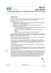
15. Supplementary Notes
Project Manager: Edward Kondrath, NJDOT
16. Abstract
The report describes the development of a Low-Cost Automated Crash Notification
System for eventual field testing on New Jersey highways. The project was
developed in response to national studies which show that nearly half of all traffic
crash fatalities occur before the crash victim reaches a trauma center. Many of
these deaths can be attributed to the inability of EMS personnel to locate and reach
the victim during the so-called “Golden Hour” after the accident when emergency
medical treatment is most effective. The goal of this project was to dramatically
reduce EMS response time by developing and testing an advanced in-vehicle
system which automatically transmits the location and severity of a crash to EMS
personnel. Specifically, the project has designed, developed, and tested a low cost
functional system that combines wireless communications and Global Positioning
Systems with a network of inexpensive sensors for crash detection.
17. Key Word
18. Distribution Statement
Car Crash
Emergency Medical Services
Wireless Communications
Automated Crash Notification
19. Security Classif. (of this report)
Form DOT F 1700.7 (8-72)
20. Security Classif. (of this
page)
Reproduction of completed page authorized
21. No. of Pages
22. Price
ACKNOWLEDGMENTS
The authors wish to acknowledge William Hoffman, Edward Kondrath, Steven
Kook, and Nicholas Vitillo of the New Jersey Department of Transportation for
their support of this research effort. The authors also wish to gratefully
acknowledge the invaluable efforts of the following Rowan University
undergraduate engineering research assistants who have made the success of
this project possible: David Browning, Aditya Chaubal, Peter Ferrara, Michael
Gilligan, Samuel Greenfeld, Devon Lefler, Amol Shah and Amip Shah.
ii
TABLE OF CONTENTS
1. Summary ...................................................................................................................1
2. Introduction and Background .................................................................................2
3. System Requirements / Architecture .....................................................................4
4. Development Approach ..........................................................................................9
5. Mobile Unit System Description ...........................................................................13
6. Base Station System Description ........................................................................27
7. Testing ....................................................................................................................34
8. Conclusions ...........................................................................................................48
9. Recommendations ................................................................................................49
10. References .............................................................................................................50
Appendix A: Source Code for the Base Station Prototype ................................51
Appendix B: SISAME Model of a Dodge Intrepid ................................................58
Appendix C: Source Code for the Mobile Unit Prototype ...................................60
iii
LIST OF FIGURES
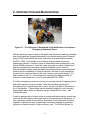
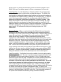
Figure 2-1. The Objective of Automated Crash Notification is to Improve
Emergency Response Times.........................................................................2
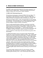
Figure 3-1. System Architecture............................................................................5
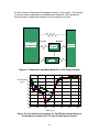
Figure 4-1. Extracted Lump-Mass Model for a 1999 Dodge Intrepid...................11
Figure 4-2. Acceleration time history for 1999 Dodge Intrepid during a frontal
barrier crashes at 25, 30, and 35 mph impact speeds .................................11
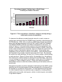
Figure 4-3. Time required for a 10 km/hour change in velocity during a crash
under various circumstances .......................................................................12
Figure 5-1. Z-World Microcontroller ....................................................................15
Figure 5-2. Trimble ACE-II GPS Unit .................................................................17
Figure 5-3. Novatel CDPD wireless modem ......................................................19
Figure 5-4. Completed ACN Rev. A unit ............................................................22
Figure 5-5. Basic Schematic of ANJEL Mobile Unit, Rev. A ..............................23
Figure 6-1. An NMEA 0183 sentence ................................................................28
Figure 6-2. Automated Crash Notification via Wireless Web .............................30
Figure 6-3. Base Station: Research Prototype..................................................31
Figure 6-4. Sample Base Station Display ..........................................................32
Figure 7-1. Micro-drop Tower Apparatus ...........................................................35
Figure 7-2. Drop tower results. ..........................................................................37
Figure 7-3. 1999 Dodge Intrepid crash pulses in Full-frontal barrier collisions at
25, 30, and 35 mph impact speeds..............................................................37
Figure 7-4. Concept Model of the Benchscale Impactor ....................................38
Figure 7-5. Air cylinder with a 3” bore diameter .................................................40
Figure 7-6. Test stand with mounted piston .......................................................40
Figure 7-7. Rails mounted to test stand .............................................................41
Figure 7-8. Carriage on rail system....................................................................41
Figure 7-9. Accelerometer mounted to testing plate ..........................................43
Figure 7-10. Schematic for data acquisition.......................................................43
Figure 7-11. Acceleration Pulses without the Mobile Unit Enclosure .................45
Figure 7-12. Acceleration Pulses with the Mobile Unit Enclosure ......................45
Figure 7-13. Acceleration Pulse of the Air Piston...............................................46
iv
LIST OF TABLES
Table 5-1. Charging Modes ...............................................................................21
Table 5-2. Cost for ANJEL Mobile Unit, Rev. A .................................................24
Table 7-1. List of Mini-Sled Tests Performed.....................................................44
v
1. SUMMARY
The report describes the development of a Low-Cost Automated Crash
Notification System for eventual field-testing on New Jersey highways. The
system was developed in response to national studies which show that nearly
half of all traffic crash fatalities occur before the crash victim reaches a trauma
center. Many of these deaths can be attributed to the inability of EMS personnel
to locate and reach the victim during the so-called “Golden Hour” after the
accident when emergency medical treatment is most effective. The goal of this
project was to dramatically reduce EMS response time by developing and testing
an advanced in-vehicle system that automatically transmits the location and
severity of a crash to EMS personnel. Specifically, the project has designed,
developed, and tested a low cost functional system that combines wireless
communications and Global Positioning Systems with a network of inexpensive
sensors for crash detection.
1
2. INTRODUCTION AND BACKGROUND
Figure 2-1. The Objective of Automated Crash Notification is to Improve
Emergency Response Times.
With the advent of trauma centers, the fatality rate of persons reaching a hospital
after a car crash has dropped dramatically over the last twenty years. However,
nearly 20,000 crash victims die every year before ever reaching the hospital
[NHTSA, 1999]. Undoubtedly, some fraction of these deaths result from
catastrophic crashes. However, many of these deaths can be attributed to the
failure of EMS personnel to reach the victim during the so-called “Golden Hour”
after the accident when emergency medical treatment is most effective.
National statistics clearly show that despite a growing wireless communications
network and the availability of medivac transport, the time to notify emergency
personnel of a crash and respond the crash victims can be quite lengthy. For
fatal crashes in the U.S., the average pre-hospital time is approximately 30
minutes in urban areas and 1 hour in rural areas [NHTSA, 2000].
Currently, emergency personnel must rely on passing motorists, highway patrols,
and traffic reporters to report crashes. Often the individual reporting the
emergency may not know where he or she is, let alone be able to direct help to
his or her location. These delays can be especially lengthy in rural, relatively
unpopulated, areas where a crash site may go undetected for hours – and
occasionally days.
Crucial to getting help to a crash victim is prompt notification that (a) a crash has
occurred, (b) the location of the crash, and (c) some measure of the severity or
injury-causing potential of the collision. Automated Crash Notification Systems
capable of performing many of these tasks have been installed as expensive
options on a limited number of high-end luxury cars. The OnStar System, for
2
example, costs $700 for installation, carries a $200-400 annual fee, and is
currently offered only for select General Motors models [Thomas, 2000].
The idea behind Automated Crash Notification is to equip cars with a crash
sensor which can detect that an accident has taken place, and automatically
notify the emergency medical personnel of the severity and precise location of
the accident. Once activated, an Automated Crash Notification system would
automatically transmit a signal to a 9-1-1 dispatch center, where an electronic
map would pinpoint the signal location. Precise location of the traveler in trouble
enables rapid emergency response. More advanced sensors can also estimate
the injury-producing capability of the crash. The first estimates of the number of
potential lives saved by ACN technology are 3000 lives per year [Champion et al,
1998].
The National Highway Traffic Safety Administration has sponsored a trial ACN
system [Preziotti et al, 2001]. This program is in the process of installing ACN in
1,000 privately owned vehicles in upstate New York. The ACN system uses onboard sensors to identify that a crash has taken place. It then uses the Global
Positioning Satellite (GPS) system and conventional cellular phone systems to
deliver a message, based on the sensors input, directly to 911 operators. While
promising, this system has proven to be extremely expensive. To date, the total
Federal cost of the study has been about $3 million. The technical approach
used in this project has resulted in an estimated $500 cost per unit – motivating a
search for a lower-cost approach to Automated Crash Notification.
Objective
The goal of this project is to develop and test an advanced in-vehicle system that
determines that a serious automotive collision has occurred and automatically
summons Emergency Medical Services (EMS) response. Specifically, the
proposed project will design, develop, and test a low cost functional system that
combines wireless communications and Global Positioning Systems with a
network of inexpensive sensors for crash detection. The purpose of the system is
not only to shorten the time it takes to notify authorities of the crash event, but to
improve the quality of the response.
This project will perform limited field tests of a prototype automated collision
notification system (ACN). A follow-on phase of this effort will seek to conduct an
operational field test of the ACN system using up to 1000 privately- or publiclyowned cars in a representative cross-section of the State of New Jersey.
3
3. System Requirements/Architecture
The Automated Crash Notification system developed under this project is
referred to as the Automated New Jersey Emergency Locator (ANJEL). ANJEL
is composed of two major subsystems: (1) the Mobile Unit which is installed in
the occupant compartment of the vehicle, and (2) the Base Station which is
responsible for receiving distress calls from the Mobile Units and reporting their
location to emergency response dispatch personnel. This section describes the
requirements of each of these subsystems.
Mobile Unit
The Mobile Unit is responsible for detecting a crash, determining the location of
the crash, and communicating crash severity and crash site location to the Base
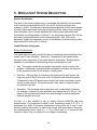
Station. Figure 3-1 presents the system architecture of the proposed device. The
system consists of a single chip embedded microcomputer which is connected to
a crash sensor, a Global Positioning System (GPS) sensor, and an embedded
wireless modem. In the event of a crash, the crash sensor(s) will detect the
vehicle impact, and output a signal proportional to the deceleration of the vehicle.
The crash sensor signal output will be continuously monitored by the
microprocessor which will decide whether or not a crash has taken place. Upon
detecting a collision, the microprocessor will poll the GPS sensor to determine
the final resting position of the car. The microprocessor will then use its wireless
modem to establish a communications link with the Base Station. Once a link
has been established, the Mobile Unit will transmit crash site location and the
crash severity to the Base Station. Ideally, the entire process, including linkup,
will be completed within 30 seconds after the crash occurred – giving EMS
personnel a crucial edge in rapidly reaching the crash victim.
The Mobile Unit will be installed either under the driver’s seat or in another
occupant compartment location. Locating the Mobile Unit in the occupant
compartment will provide an accurate measure of the deceleration experienced
by the occupants in a crash, and will protect the Mobile Unit with the same
structural cage which protects the occupants.
Note that there is some degree of overlap between the Mobile Unit and
components in late model cars. Since the early 1990’s, all passenger vehicles
sold in the U.S. have been required to have airbags. Increasingly, the sensors
used in these systems are electronic sensors of the type used in this program.
However, modification or connection to the airbag or any other safety systems of
the car has been strictly avoided in the Mobile Unit for liability reasons.
Eventually, automakers may choose to use the airbag sensor to drive an ACN
systems of the type described here. However, the Mobile Unit has been
designed to be completely independent of all in-vehicle systems with the
exception of the car battery.
4
GPS
Sensor
Crash Sensor
Embedded
Microprocessor
Embedded
Wireless
Modem
Power
Figure 3-1. System Architecture
Base Station
The Base Station system will (1) receive the emergency call over the Mobile Unit,
(2) receive GPS data and the crash pulse from the crash site, and (3) display the
location and severity of the crash using computerized maps for Emergency
Response Team dispatch. The prototype Base Station will (1) serve as a test
bed for later development into a full-featured Base Station in later phases of the
project, and (2) for checkout of the prototype in-vehicle device proposed here.
Note that this system is intended only for laboratory use: it is not intended for use
as a production system.
Mobile Unit Functional Requirements
Crash Detection. Crash detection will be performed with an array of
accelerometers. Detection of frontal impacts requires an accelerometer aligned
with the longitudinal axis of the car (x-axis) while detection of side impacts
requires an accelerometer aligned with the lateral axis of the car (y-axis). Note
that the x-axis accelerometer will detect rear impacts in addition to frontal
impacts, and a single y-axis accelerometer will detect both driver and passenger
side impacts. Angled impacts or frontal offset impacts would detect accelerations
along both axes.
5
A minimum of two sensors is required to detect front, side, rear, angled, and
offset impacts. In the U.S. these accident modes account for the majority of all
accidents. The system developed under this program is a two-axis system.
Depending on system cost constraints, additional sensors could be added to the
system to complement this minimal sensor set. Other sensors such as a third
sensor in the vertical direction (z-axis) would provide a complete acceleration
time history including vehicle pitching during impact. However, a review of
NHTSA frontal, side, and frontal-offset crash test data suggest that z-axis
acceleration is negligible compared with the x-axis and y-axis acceleration. It
should be noted that the two-sensor system cannot detect rollovers. Either a
dedicated roll sensor, or a second sensor in the z-axis, separated from the first zaxis sensor by a known distance would allow detection of rollover.
The system uses a newly developed low-cost crash sensor – the Analog Devices
ADXL-250. These crash sensors are inexpensive silicon based accelerometers
which were initially developed for airbag systems, and cost two orders of
magnitude less than conventional accelerometers.
GPS Sensor. The system uses a newly developed low-cost GPS sensors – the
Trimble ACE-II system and the Conexant Zodiac System. These sensors can
provide location resolution under 30 meters. Two options were investigated for
GPS data processing for the mobile unit. The first option was to use a turn key
single board system which processes the raw GPS data on board to determine
the position of the car. The second option considered was to transmit the raw
GPS data directly to the Base Station that will compute crash site location using
a more powerful computer. However, early concerns that the computationally
more intensive first option might introduce unacceptable time delays proved to be
unfounded. All prototype development used the onboard GPS option.
Wireless Communications Transceiver. The system uses Cellular Digital Packet
Data (CDPD) wireless transmission technology. CDPD is a cutting edge
wireless communications protocol which allows direct connection of the remote
devices to the Internet.
Embedded Microprocessor. System performance is controlled by an embedded
single chip microcomputer. Single chip microcomputers such as the MicroChip
PIC series, Z-World series, or Motorola 68HC12 series combine onboard
memory, reasonable clock rates, and onboard A/D capability into a low-cost
package which is readily interfaced to sensors such as those used in the ANJEL
system.
Power. Power for this system is provided by the passenger car 12-volt electrical
system. Note that per our design guidelines this is the only interconnection
between Mobile Unit and the passenger car. Power from the car battery will be
conditioned as necessary before input to the Mobile Unit electronics. Storage of
6
backup power in a small onboard battery permits successful operation of the
Mobile Unit even if car battery power is lost as a consequence of the crash.
Crash Algorithm. A crash algorithm, a software module in the microprocessor,
was developed to detect a crash while avoiding false alarms. The Mobile Unit
must be able to distinguish between actual crashes and low-severity crashes or
non-crashes such as panic braking or backing into a shopping cart. To detect a
crash, the microprocessor samples the accelerometer output at 1000 Hz (1
sample per millisecond). Based upon examination of National Highway Traffic
Safety Administration crash tests coupled with crash test modeling, the crash
detection algorithm was designed to signal that a crash has occurred if a 10miles/hour change in velocity occurs in under 50 milliseconds. To put these time
intervals in perspective, the typical frontal-barrier crash has a duration of
approximately 150 milliseconds while panic braking requires over 1000
milliseconds.
Message Content. When a crash is detected, the Mobile Unit must transmit a
message to the Base Station which describes the crash location and severity.
Knowledge of the crash location allows the EMS center to dispatch EMS crews to
rescue the crash victim. Knowledge of the crash severity provides the EMS
center with an early snapshot of the seriousness and potential injury
consequences of the accident. The message to the Base Station must include
both these data facets as well as information detailing the time of the crash and a
description of the car. Crash location can be as straightforward as the GPS
location longitude and latitude. Crash severity will be provided for each crash
sensor, and will be either the change in velocity or the crash pulse along each
axis. It should be noted that while the crash pulse requires transmission of a
longer message, the crash pulse typically provides sufficient information to infer
whether the car struck a tree or another car (which may require additional EMS
personnel). Inclusion of crash severity for each axis allows the Base Station to
distinguish between frontal and the potentially more serious side impacts.
Crash Survivability. The Mobile Unit must be capable of surviving and properly
functioning after a crash. The unit, its enclosure, and necessary antennas must
be designed to survive crash loadings (typically 30 G in a 35 mph crash) and
potential of power after the crash. Antennas for GPS and wireless transmission
must survive the crash so that the crash location can be determined and
notification of the crash event can be transmitted to the Base Station. As not all
transmissions between the Mobile and Base Unit may be received, the Mobile
Unit must be designed to transmit multiple times. Crash survivability can be
increased through several means including (1) backup battery power, (2) locating
the Mobile Unit inside the occupant compartment ‘cage’, (3) taking GPS
measurements repeatedly during normal driving, and transmitting the last known
location to the Base Station if the GPS lock is lost. The post-crash operation of
the system was evaluated in laboratory testing at Rowan University.
7
Base Station Functional Requirements
The Base Station system must (1) receive the simulated emergency call over the
Mobile Unit, (2) receive GPS data and crash severity from the simulated crash
site, and (3) display the location and severity of the simulated crash using
computerized maps for Emergency Response Team dispatch. Design concerns
include how to best present crash location and severity to the Base Station
operators, and how to ensure that large numbers of calls can be handled
simultaneously.
The long-term objective of the ACN system, which will not be conducted under
this research effort, will connect the Mobile Units with existing or expanded 911
systems. However, this effort will require coordination with existing 911 system
operators and careful attention to how best to present crash information
graphically to operators who are more accustomed to receiving voice-only calls.
The Base Station developed here will provide an early evaluation of possible 911
operator user interfaces. The Base Station may also be suitable for limited field
testing of the system for captive fleets such as the State Police or NJDOT
vehicles.
8
4. DEVELOPMENT APPROACH
The ANJEL system required the development of two major components: (1) a
Mobile Unit and (2) a Base Station. This section describes the development
strategy to design, build, and test each of these components.
4.1 Mobile Unit: Development Approach
The development strategy was to develop the Mobile Unit in two stages. The
first stage was to demonstrate proof of concept. The second stage was to
explore designs which would lead to a lower cost Mobile Unit. While important,
reduced cost was to be attempted only after successful proof of concept. To
attack these two design criteria, a series of prototype Mobile Units was planned
for development. The first prototype, Rev. A, would be designed to demonstrate
proof-of-concept. The second prototype, Rev. B, would extend Rev. A, and
would be designed to explore consumer cost reductions.
Proof of concept required the design, fabrication, and testing of a prototype
Mobile Unit which could a) detect a crash, b) determine crash location, and c)
transmit crash severity and location to a Base Station. These were the primary
design objectives for the first prototype, i.e. to demonstrate functionality.
Although other design considerations, e.g., cost, size, power requirements, ease
of installation, and crash survivability, would be important in the eventual
production Mobile Unit, these design criteria were relaxed during pursuit of the
first prototype.
To facilitate demonstration of proof-of-concept and retain maximum design
flexibility, Rev. A was envisioned as a ‘research prototype’. Rev. A was intended
to serve as a test bed for potential ACN technologies – including crash sensors,
GPS chip sets, and wireless communication components. Rev. A was designed
to be as modular as possible so that alternate components, e.g. GPS boards,
could be readily swapped into and out of the prototype Mobile Unit to investigate
improved performance. Rev. A was also designed with numerous internal
diagnostics to track and allow debugging of system performance during operation
in the field. Finally, because this was to be a research prototype, cosmetic
packaging concerns were postponed until the development of later prototypes.
This allowed antennas, for example, to be placed where convenient for testing as
opposed to attachment points more aesthetically pleasing to a consumer.
Similarly, this approach allowed power for the Mobile Unit to be obtained from the
car cigarette lighter adapter rather than directly connecting to the car’s electrical
system.
The second prototype, referred to as Rev. B, in this document, would be
designed using a fully functional Rev. A prototype as a starting point. While
maintaining the functionality of Rev. A, Rev. B would explore the possibility of
9
lower cost approaches to Automated Crash Notification. The objective was to
design, build, and test a second prototype which could be fabricated in quantities
suitable for field testing in New Jersey.
4.2 Base Station: Development Approach
To test both of these prototypes, a Base Station was developed which could field
calls from the Mobile Units, and simulate the operation of a future automated
crash notification 9-1-1 center. A key objective of the Base Station was to
provide a means to test Mobile Unit wireless communication, i.e., to receive
ACN messages from the Mobile Units, and to plot the location of these Mobile
Units on a computerized map. A second objective was for the Base Station to
serve as the test bed for evaluating automated mapping products. To limit
development costs, the research team sought to use commercial-off-the-shelf
software and mapping products whenever possible.
Note that the Base Station developed under this project was intended solely as a
means to test correct operation of the Mobile Unit. While it is hoped that our
Base Station design may provide some guidance for future 911 centers, the
current Base Station is in no way intended to serve as a replacement for current
911 dispatch centers.
4.3 Crash Determination
One of the key functions of an ACN system is its ability to determine whether a
crash has occurred or not. This makes the design of this sub-system very
critical. One possibility would be to monitor the airbag sensor in the car, and
trigger the crash notification system in the event that the airbag deploys.
However, modification or connection to the airbag or any other safety system of
the car was avoided for liability reasons. While automobile manufacturers may
eventually choose to use the airbag sensor to drive an ACN system, it was
decided to monitor the vehicle’s acceleration profile to determine whether or not
a crash had occurred.
An Analog Devices ADXL250 dual axis accelerometer was chosen to monitor the
acceleration felt by the car. This accelerometer was chosen for a number of
reasons. One main reason was the small size – a mere 0.4” x 0.3”. Moreover,
the fact that it is a dual axis accelerometer allows us to monitor the acceleration
in both the x and y directions. This allows the system to detect both frontal as
well as side impacts. Also, the accelerometer has a range of +/- 50 g. Even in
30 mph accidents, the passenger compartment often feels up to 30 g’s. Hence, it
is important to make sure that the range of the accelerometer is sufficiently broad
to avoid saturation.
During normal operation, the acceleration values from the accelerometer will be
logged by the micro-controller, which will then integrate these values over a 40
10
ms time interval to determine the change in velocity of the vehicle. This change
in velocity is then compared to a predetermined threshold, which allows the
microcontroller to determine whether or not a crash has occurred.
Occupant
Compartme
Firewall
Radiator
Barrier
Engine
Wheels
Figure 4-1. Extracted Lump-Mass Model for a 1999 Dodge Intrepid
0
Acceleration-5
(g’s)
-10
-15
-20
-25
-30
-35
-40
0.000
0.025
0.050
0.075
0.100
0.125
0.150
Time (sec)
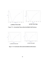
Figure 4-2. Acceleration time history for 1999 Dodge Intrepid during a
frontal barrier crashes at 25, 30, and 35 mph impact speeds
11
Percentage of Impacts That Experience a 10km/h Change
in Velocity at or Below a Time Value
Percentage
120
100
80
60
40
20
0
27
28
29
30
31
32
33
34
35
36
Time (ms)
Figure 4-3. Time required for a 10 km/hour change in velocity during a
crash under various circumstances
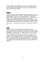
To determine the different possible threshold values for a crash, numerous
crashes were simulated using the SISAME impact simulation code developed by
NHTSA [Mentzer, 1999]. First, a model of a 1999 Dodge Intrepid was extracted
using crash test data available from the NHTSA Vehicle Crash Test Database.
The detailed SISAME model file is provided as an appendix to this report. As
shown in Figure 4-1, this model uses a system of non-linear springs and lumpmasses to simulate a vehicle’s structural response during a collision. Using this
model a crash simulation was conducted. Figure 4-2 shows the outputs from the
program in terms of acceleration pulses for the impact. These pulses were
integrated to find the change in velocity of the vehicle. These simulations were
then repeated using a range of speeds varying from 25-70 mph. By analyzing
the results from each simulation, the time for a 10 km/h change in velocity during
a crash was found. Figure 4-3 shows that for the simulations run, the maximum
time required for a 10 km/h change in velocity was 36 milliseconds. If the driver
in a car traveling at 60 mph slams on the brakes, it takes about 500 milliseconds
to undergo a 10 km/h change in velocity. Clearly, this method successfully
differentiates between a crash-like situation (slamming on the brakes) versus an
actual crash.
Although this algorithm should be adequate for field-testing of the ANJEL system,
additional test and simulation data should be evaluated prior to development of
an algorithm for a production ACN system. The final algorithm should set crash
/no-crash threshold based on additional crash configuration, including different
vehicle makes and models, side impacts, vehicle to vehicle impacts, and vehicle
to rigid barrier impacts.
12
5. MOBILE UNIT SYSTEM DESCRIPTION
System Architecture
The goal for the initial prototype was to investigate the feasibility and workability
of the concept involved with the ACN. As a result, the first prototype (also
referred to as Rev. A) adhered to the baselines established for the overall design.
No major flaws were found during the prototyping efforts, and no major changes
were necessary. Rev. A hence manifests the same system architecture and
functionality as outlined earlier in Section 3. An advanced prototype (Rev. B) has
also been constructed based on the same architecture. Rev. B is a more
advanced, slightly less expensive version of the Mobile Unit which corrects minor
flaws detected in during Rev. A testing.
Crash Detection Subsystem
Silicon Accelerometer
The crash algorithm used in the ACN relies on measuring the acceleration of the
vehicle (see “Crash Algorithm,” Section 4). Consequently, the accelerometer
becomes a key component of the crash detection subsystem. Several factors
needed to be considered in determining which accelerometer to use:
•
Size. The system should be as compact as possible, since it needs to be
portable. Additionally, several physical and spatial constraints are imposed
by the potential location of the system in existing cars.
•
Dual axis. Although Rev. A focuses on the detection of frontal impact, the
long-term goal of the ACN is to be a fully functional crash detection system.
Consequently, the ACN would need to detect two kinds of accidents: frontal
as well as side impacts. The accelerometer, then, needs to acquire data in
two directions as well.
•
Saturation. Car accidents tend to take place over a wide range of impacts.
For example, victims in 30 mph accidents may experience up to 30 g’s. The
range of the accelerometer needs to be wide enough to ensure the system
does not saturate at low g’s.
For Rev. A, it was decided to use an Analog Devices ADXL250 dual axis
accelerometer. The component is small in size, measuring a mere 0.4” x 0.3”. It
possesses the ability to measure accelerations along both the X and Y axis,
thereby enabling the system to detect both frontal and side impacts. Moreover,
the accelerometer has a range of +/- 50 g. Since Rev. A is concerned with
crashes to about 30 g, the system is in no danger of saturating.
13
Since Rev. A has been limited to the detection of frontal crashes, readings from
the accelerometer are only considered along the X-direction. The process can be
modified, however, to allow for inclusion of readings along the Y-direction.
Sample-and-hold Chip
The A/D converter is continuously connected to the onboard accelerometer.
However, the A/D converter samples the accelerometer only at discrete time
intervals. In addition, the analog-to-digital conversion process requires a finite
amount of time. Since the voltage inputs to the A/D will change continuously,
failure to “hold” a voltage sample during the A/D process may skew the data. To
rectify such an error, the SMP04E (which is a sample & hold chip) is used
between the accelerometer and the A/D unit. This will ensure all data points are
properly recorded during the detection of a crash. Moreover, by setting a high
sample rate (1000 times per second), we can account for the discreteness of the
data.
A/D Converter (ADC)
The ACN uses an external voltage comparator to compare readings from the
accelerometer to certain threshold voltage values. Whenever the voltage
exceeds the threshold, the ADC chip (ADC0809CCNA) sends an interrupt signal
to the microcontroller, which processes this data to determine if a crash has
occurred or not. The ADC has 8 analog input channels. Using the address latch
in the ADC, the desired input can be converted to an 8-bit digital stream. The
stream is then assigned to the data bus and read to a particular address location
on the micro-controller (the address used is 0x40C1). This acceleration data is
stored in the RAM (Random Access Memory) in the form of a circular buffer of
size 128. If the micro-controller detects a crash, the contents of the buffer are
written out to the RS-232 output from where they can later be acquired by an
external device. The ‘C’ code for this program is shown in the file “A_DACN.cpp,”
which is included in Appendix C at the end of this report.
14
Microcontroller
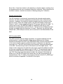
Figure 5-1. Z-World Microcontroller
A Z-World CM7200 microcontroller was used for Rev. A. The specifications are
as follows:
Size
Microprocessor
SRAM
EPROM
I/O
1.8” x 2.05”
Z180 running at 9.216 MHz
32 K
128K flash EPROM
2 Serial Ports
2 DMA Channels
2 Programmable Timers
One of the main reasons that this microcontroller was chosen was the support it
offered for programming in Dynamic C, which is a variant of traditional C. This
along with the vast library support offered by Z-World has helped speed up
development time.
The microprocessor used in Rev. B is the PIC17C756A processor. It has a clock
speed of 33 MHz and is widely used in industry. The main features of the PIC
chip as listed in the user manual are as follows:
Speed
Size
Approx Price
I/O
Timers
A/D converter
Brown-out
33 MHz
1.65” x 2.34” (68 pin PLCC)
$10.00
2 USART interfaces
4 + watchdog timer
12 channel 10-bit ADC
Yes
15
reset
SRAM
EPROM
902 bytes
None
One of the main advantages of using the PIC micro-controller is that it is much
less expensive than the Z-World processor. This makes it more suitable for
applications such as the ACN where the cost of the final product is important.
Additionally, the PIC17C756A has a 10-bit A/D converter which can be used to
take in data directly from the accelerometer. This eliminates the need for an
external ADC and reduces valuable board space requirements leading to a less
expensive, more compact final product. Just as with the Z-World processor, the
PIC chip uses C, a widely used programming language.
Functionality
As mentioned earlier, the Rev. A microcontroller receives input from the A/D
converter to a specific memory location (0x4104). The micro-controller then
assigns a value of ‘1’ to this address. This assignment serves as instruction to
the ADC to hold the voltage sample that it currently sees on its X-axis input.
Following this, a value of ‘0’ is written to the address 0x40C1, which initiates
analog to digital conversion. When the conversion is completed, the ADC sends
an interrupt signal to the microcontroller. It should be noted that the value on the
data bus will hence represent the acceleration reading at that particular instant of
time. After the interrupt signal, a value of ‘1’ is reassigned to the address 0x4104.
This tells the ADC to release the held value of voltage. The acceleration reading
acquired by the micro-controller is then stored in the circular data buffer. It is
compared with preceding values to ascertain whether a crash has occurred or
not. If a crash is detected, the data buffer is written out through the
microcontroller’s serial I/O channel; if no crash has occurred, the above loop is
repeated. The ‘C’ code for algorithm is shown in the file “crastest.cpp,” included
in Appendix C at the end of this report.
The microcontroller continuously logs acceleration values from the accelerometer
every millisecond. It monitors the data in 40 millisecond pieces to determine if a
crash has occurred. It also updates the vehicle’s location from the GPS unit
every second. The software implemented for this is primarily interrupt-driven.
Both the A/D unit and the GPS unit generate interrupts when the microcontroller
needs to read a value. In the event that the microcontroller detects that a crash
has occurred, it proceeds to wake up the wireless modem from sleep mode, and
instructs it to begin emergency transmissions.
16
Crash Site Location Subsystem
GPS System
System Description
GPS is one of the only systems available today that can pinpoint one’s exact
position on the earth anytime, in any weather, anywhere. Twenty-four GPS
satellites continuously orbit the earth at a height of 11,000 nautical miles. These
satellites transmit signals that can be detected and used by anyone with a GPS
receiver to determine one’s location with great precision. Consequently, the GPS
system is an integral part of a crash notification system, as it is needed to
determine the location of the vehicle during a crash.
Various companies were researched before a GPS receiver was selected.
These companies include Motorola (www.motorola.com), Trimble
(www.trimble.com) and SiRF (www.sirf.com). Important considerations in the
purchase of the GPS receivers include their accuracy, locking time for a signal
and their ruggedness to vibrations, g-force and so on. All three companies have
a host of GPS products that could be used for this application.
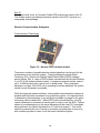
After much consideration, the Trimble ACEII GPS core module was chosen for
Rev. A. Since the ACEII is a core module, it is designed for OEM applications.
The specifications of this GPS module are as follows [Trimble, 1999]:
Figure 5-2. Trimble ACE-II GPS Unit
Channels
Update rate
Accuracy
Acquisition (typical)
Reacquisition after signal loss
Velocity
Operating temp
8-channel continuous tracking receiver
NMEA @ 1 Hz
25 m (50%) without S/A
Cold start: < 130 seconds (90%)
Warm start < 45 seconds (90%)
Hot start: < 20 seconds (90%)
< 2 seconds (90%)
515 m/sec maximum
-40 C to +80 C
17
Power consumption
I/O protocols
Primary: 5 V DC, +/- 5%
GPS board only; 155 mA, 0.78 watts
With antenna: 180 mA, 0.9 watts
TSIP (binary data)
NMEA 0183 v2.1 (ASCII data)
TAIP (ASCII data)
The GPS board is capable of outputting coordinates using various I/O protocols.
For our application, we will be using the NMEA protocol, as this protocol has
been standardized. One issue of concern here is the power consumption for this
unit. However, since the unit will be running off the car battery, this is not a major
concern. The acquisition times as well as the accuracy of this unit are
reasonable.
Functionality
The GPS unit is triggered by the microcontroller as soon as the car is turned on.
Within minutes, the GPS receiver locks onto the satellites and is able to pinpoint
the location of the car. Thereafter, the GPS unit updates the position of the
vehicle every second as long as the car is on. As a result, even if the GPS
antenna is damaged and the satellite lock is lost during a crash, the
microcontroller will have the position of the car to within a second before the
crash.
For testing purposes in Rev. A, the GPS output is read into a computer using RS232. However, as the GPS actually outputs TTL logic levels, once the GPS unit
is embedded into the system, no interface will be required between the GPS unit
and the microprocessor. The ‘C’ code for this operation is shown in the file
“CDPD_GPS.cpp,” included in Appendix C at the end of this report.
Antennas
A major concern related to the usage of GPS is its antenna. While special care
can be taken to ensure to crashworthiness of the antenna, there is always the
possibility that the antenna may be destroyed in a crash, thereby rendering the
system useless. To combat any such issues, it was decided that the GPS unit
should automatically update the vehicle location every second. As a result, even
if the GPS antenna is lost in a crash, the system will still be able to transmit the
last known position – which, given the sample rate, will be to within a second
before the crash. Note that two antennas are required for the system: one fore
the GPS, and one for CDPD communication. For Rev. A, the two antennas
received from the GPS and CDPD vendors were used in their modified form.
18
Rev. B
To achieve lower costs, a Conexant Zodiac GPS receiver was used in Rev. B.
The Zodiac receiver provides performance similar to the ACE-II receiver in a
comparably sized package.
Wireless Communication Subsystem
Communication Technology
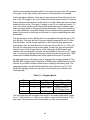
Figure 5-3. Novatel CDPD wireless modem
There are a number of possible wireless technologies that can be used for the
transmission of the vehicle’s location. These technologies include Radio
Frequency (RF), cellular and Cellular Digital Packet Data (CDPD) modems
among others. Rev. A, uses a CDPD modem manufactured by Novatel Wireless.
It is a 0.6 W full duplex wireless modem. It supports maximum transfer rates of
up to 19,200 bps and uses a mere 8 mA in sleep mode. This is important
because in a crash, if the ACN unit is operating on backup batteries, the system
should use as little power as possible.
While this approach seems sufficient, other possible communication means are
possible and should be considered for a production system. An important issue
in determining the technology to use will be the available coverage for the given
technology versus related cost. While CDPD performs satisfactorily, it would
require consumers to purchase a monthly plan in order to use the ACN. Cellular
seems to be advantageous in this sense because with the new E911 standards
being enforced, any carrier that detects a 911 call must accept it. This would
save the consumer the cost of having to purchase a monthly plan of some sort
with a cellular provider in order to use the crash notification system.
19
Antenna
The cellular antenna is of even greater concern than the GPS antenna, for if this
antenna is lost, no transmissions will be possible. Multiple antennas for the
cellular unit, possibly in the front and the back of the car would be advantageous,
as this would give maximum antenna survivability in a crash. However, there are
other issues related to the number and location of antennas. Wires must be run
from each antenna to the crash notification box, and an excessive number of
antennas would intensify the associated labor, thereby reducing the ease of
installation of the system. Moreover, aesthetics is also a very important issue.
The presence of antennas in safe but obscure locations might actually have an
adverse affect on the marketability of the product as far as the consumer is
concerned. More studies need to be conducted in this area to determine the
consumer’s preferences.
Power Requirements
Rev. B
The ACN power system consists of a power conditioning system of the various
filters and regulators required to convert the 12V DC from the car battery into the
necessary DC voltages vital to the internal circuitry. The power system also
includes a back-up battery pack complete with its own charger and a mechanism
for switching between primary and back-up power consumption modes.
All of the circuitry relies on 5V DC with the exception of the CDPD modem for
which 3.6V DC must be supplied. In addition, a 5V analog reference is needed
for the A/D converter onboard the microcontroller. To provide each of these
required voltage levels, a voltage regulator is used. Each regulator is supported
by an EMI (electromagnetic interference) filter and bypass and bulk capacitors.
An LM2940 linear voltage regulator provides the 5V DC supply, while an LM4040
provides the 5V analog reference. An LT1098 sources the 3.6V DC supply.
The back-up battery system is composed of 5AA NiCd batteries and the
supporting charge system. Each battery has a cell voltage of 1.2V giving the total
battery pack a voltage of 6V. The 12V input from the car battery and the battery
pack outputs are both connected through power diodes to the to the inputs of the
three regulators. When the 12V from the car battery is removed, the battery pack
diode becomes forward biased and continues delivering power to the regulators.
Specifically, Schottky diodes are used such that there will be a minimal voltage
drop across the diodes.
A p-MOS switch, installed between the battery pack and its diode, is the means
for switching battery pack power into and out of the rest of the circuit. The p-MOS
20
switch is closed when presented with 0V at its gate and open when 5V is present
at the gate. In this way, battery pack power is conserved when not needed.
Under operating conditions, there are two circumstances that would result in the
loss of the 12V supply to the circuit. Either the car has been turned off, or the car
battery has been disconnected as the result of a crash. When the microcontroller
senses the loss of the 12V supply, it checks to see if it is a valid crash state. If it
is not, the microcontroller leaves the p-MOS switch open and the battery pack
does not supply power to the circuit (system shutdown). If the microcontroller is
in a valid crash state, the p-MOS switch is closed and the battery pack provides
power to the circuit so that there is still power to continue transmitting the crash
coordinates.
The actual control of the p-MOS switch is accomplished through the use of a Dtype flip-flop. The clock and the D input are directly connected to port D of the
microcontroller. A state change operation in the D-type flip-flop requires two
occurrences. First, the data bit at the D input must be set (0V for on, 5V for off).
Second, the clock must receive a rising edge. On start-up, the microcontroller
sets the output of the D-type flip-flop to 0V, closing the p-MOS switch, and
checks to be sure that back-up power will be available in the event of 12V supply
loss. To prevent any leakage current from flowing into the microcontroller, 10kΩ
resistors are installed between the flip-flop inputs and the port D terminals.
As stated previously, the battery pack is supported by a charging network. The
MAXIM 1640 charging chip is employed to PWM (pulse width modulate) a 1mH
inductor to provide a constant current level for charging the battery pack. The
charging chip has a two-bit interface with the microcontroller at port C. This
allows the charging mode to be set by the microcontroller as outlined in the
following table:
Table 5-1. Charging Modes
D1
0
0
1
D0
0
1
0
Mode
Off
Top-Off
Pulse-Trickle
1
1
Fast Charge
Output Current (A)
0
VSET/(13.3Rsense)
VSET/(13.3Rsense)
12.5% Duty Cycle
VSET/(13.3Rsense)
The only mode that will be used in this design is the pulse-trickle mode, where
VSET= 1.145V and Rsense= 0.56Ω so the output current is 154mA with a 12.5%
duty cycle. This mode can be set during start-up of the microcontroller.
21
Conclusion
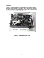
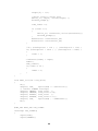
Figure 5-4 shows a photograph of the completed Rev. A prototype. Figure 5-5
presents a overall schematic of the system. Table 5-1 provides cost estimates
for the Rev. A system. A similar calculation of costs for Rev. B estimated Mobile
Unit costs in quantities of 1000 at $400-450 per unit.
Figure 5-4. Completed ACN Rev. A unit
22
Figure 5-5. Basic Schematic of ANJEL Mobile Unit, Rev. A
23
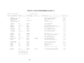
Table 5-2. Cost for ANJEL Mobile Unit, Rev. A
ACCEL Bill of Materials
acn_design_b1.sch
============================================================================================================================
Count ComponentName
RefDes
PatternName
Value
Description
Cost ($)
------ --------------- --------------- --------------- --------------- ----------------------------------------------------1 CM7200
U1
CM7200 Core module (Z180)
99.00
1 EXPEDITE_MODEM H2
IDC26M
Novatel Expedite Modem
230.00
1 ANTENNA CABLE
Modem Antenna Cable
19.99
1 GPS_ACEII
U3
IDC8M_2MM
GPS Unit
160.00
1 MAGMOUNT ANTENNA
GPS Unit Antenna
45.00
1
1
2
1
1
1
1
1
2
74HCT02
74HCT32
LMC662
LP339NA
MAX232
74HCT259
74HCT374
74HCT541
74LVX4245
U9
U13
U22, U25
U19
U2
U12
U8
U24
U20, U23
DIP14
DIP14
DIP8
DIP14
DIP16
DIP16
DIP20
DIP20
SOIC_24
Quad 2-Input NOR
Quad 2-Input OR
Dual Operational OpAmp
Ultra-Low Power Dual Comparator
RS-232 Transciever
8-Bit Addressable Latch
Octal D-Type Register
Octal Buffer/Line Driver
3.3V/5V Level Shifter
0.39
0.41
3.26
1.40
3.31
0.85
0.83
1.05
3.34
1
1
1
1
1
3
1
1
V33ZA2
LT1086
LM2940
NJM7809
LM4040
EMI_FILTER
IND
1N5404
U30
U15
U16
U17
U14
L1, L2, L3
L5
D1
V33ZA2
TO-220
TO-220
TO-220
TO-92
SMT
IND400
267_03
MOV - 26 V
3.6V/1.5A Low Drpt. Regulator
5V/1A Low Drpt. Regulator
9V/1.5A Regulator
5V Precision Reference
10000pf/50V EMI Filter
High Current Toroid
400V/3A Silicon Rectifier
0.54
3.75
2.45
0.63
3.47
2.10
7.75
0.05
1
1
1
1
1
1
ADC0809CCNA
ADXL250_SOP
SMP04
LM34
MX7528
MXO45
U4
U7
U5
U21
U26
U31
DIP28
SOIC_14
DIP16
TO-92
DIP20
DIP8
2 CAP100
29 CAP200
C2, C3
CAP100
C4,
CAP200
C5, C6, C7, C8,
C9, C10, C11, C12,
C13, C14, C15, C16,
C17, C18, C19, C20,
C21, C24, C25, C26,
24
10000pF
275 uH
8 Bit uP Compatible A/D
Dual Axis Accelerometer
Sample & Hold
Temperature Sensor
DAC Unit
Crystal Oscillator (1 MHz)
10 pF
0.1 uF
10 pF/100V Ceramic Capacitor
0.1 uF/50V Ceramic Capacitor
6.90
23.94
8.15
8.44
7.11
2.78
0.38
3.48
5 POLCAP
2
2
1
6
CAP_SMT_10UF
CAP_SMT_20UF
CAP_SMT_33UF
CAP_SMT_100UF
3 RES400
1 RES500
24 TEST_POINT
C29, C31, C35, C37,
C39, C42, C43, C45
C32, C34, C41
CAP100RP
C44, C49
C48, C50
CAP_SMT_B
C27, C33
CAP_SMT_C
U27
CAP_SMT_D
C22, C23, C30, CAP_SMT_G
C36, C46, C47
R6, R7, R8
RES400
R1
RES500
TP1, TP2, TP3, TEST_POINT
TP4, TP5, TP6,
TP7, TP8, TP9,
TP10, TP11, TP12,
TP13, TP14, TP15
TP16, TP17, TP18
TP19, TP20, TP21
TP22, TP23, TP24
1 uF
10
20
33
100
10k
400
uF
uF
uF
uF
1 uF/16V Tantalum
1.20
10uF/16V Alum Elec. SMT
20uF/16V Alum Elec. SMT
33uF/16V Alum Elec. SMT
100uF/35V Alum Elec. SMT
0.62
0.72
0.42
4.80
Resistor 1/4W, 5%
Resistor 1/4W, 5%
Test Points
0.18
0.06
3.52
2.49
3.63
3 JUMPER
1 CM7000
H3, H4, H5
U1
IDC8M_2MM
CONN40M
2mm 8 pin Header
40 Pin Connector for CM7200
1
1
1
1
1
H1
IDC26F
26 Pin Header for External Box
26 Pin Connector for External Box
Receptacle for outer box
Plug for outer box
Cable clamp for outer box
1.66
2.07
30.40
58.64
6.42
Heat Sink – TO220
Backup battery (1.2 V, 600 mAHr)
0.96
18.00
26PIN_HEADER
26PIN_CONN
93F1233
91F8568
93F1233
3
6
SUB-TOTAL FOR ACN UNIT
3
1
1
1
1
906-3174
EG1957
226-1011
APPP-001
EG1500
Square post receptacle
3 pos switch
Switch knob
Cigarette Adapter plug
Rocker switch (Power)
SUB-TOTAL FOR DEV UNIT
TOTAL COST FOR ACN PROTOTYPE
25
786.54
10.89
5.07
4.55
2.25
1.78
24.54
811.08
ADDITIONAL COSTS INCLUDE PCB FABRICATION, RAW MATERIAL AND OTHER MECHANICAL COSTS (WASHERS, SCREWS, ETC.)
26
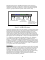
6. BASE STATION SYSTEM DESCRIPTION
In the event of a crash, the Mobile Unit will automatically notify the Base Station
of the crash via a wireless communications link. The functions of the Base
Station system are to (1) receive the simulated emergency call from the Mobile
Unit, (2) retrieve GPS data and crash severity as transmitted by the Mobile Unit,
and (3) display the location and severity of the simulated crash using
computerized maps for Emergency Response Team dispatch. Design concerns
include how best to present crash location and severity to the Base Station
operators, and how to ensure that large numbers of calls can be handled
simultaneously.
The discussion below will detail the Crash Notification Message Content,
approaches for Crash location mapping, the wireless web communication
strategy, and the software implementation.
Message Content
After detecting a crash, the Mobile Unit must transmit a message to the Base
Station which describes the crash location and severity. Knowledge of the crash
location allows the EMS center to dispatch EMS crews to rescue the crash
victim. Knowledge of the crash severity provides the EMS center with an early
snapshot of the seriousness and potential injury consequences of the accident.
The message to the Base Station should include both these data facets as well
as information detailing the time of the crash and a description of the car. Crash
location can be as straightforward as the GPS location longitude and latitude.
Crash severity should be provided for each crash sensor, and can be either the
delta-velocity or the crash pulse along each axis. It should be noted that while
inclusion of the crash pulse requires transmission of a longer message, the crash
pulse typically provides sufficient information to infer whether the car struck a
tree or another car (which may require additional EMS personnel). Inclusion of
crash severity for each axis allows the Base Station to distinguish between
frontal and the potentially more serious side impacts.
Crash Location
The Crash Location is the single most important data facet transmitted by the
Mobile Unit. In order to extract meaning from the GPS messages sent from the
Mobile Unit, the form of the data (i.e.: binary, ASCII, delimited, continuous, etc)
and the interface it would require (i.e.: modem, serial port, etc) must be clearly
defined. Current GPS devices provide several different options for GPS
coordinate output. The most widely used format, however, is that set by the
National Marine Electronics Association (NMEA). Of the three versions of the
NMEA standards that were found, the NMEA 0183 was the most recent and
workable. This standard, originally set for marine instrumentation, dictates both a
27
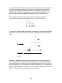
data and interface protocol. The NMEA transmissions consist of strings of
printable ASCII characters, carriage returns, and line feeds. Comma delimited
“sentences”, such as the one in Figure 6-1, are sent in succession through the
serial port, typically at 4800 baud. [Trimble, 1999; Conexant, 1999]
$GPGLL,3744.953,N,12225.319,W,182220,
device
time
37 degrees
type
18:22:20
44.953 minutes
A = valid
string North of equator
122 degrees V=invalid
type
25.319 minutes
indicates NMEA sentence
Checksum
West of prime meridian
(cumulative XOR sum
that the base station should
get if sentence is intact)
Figure 6-1. An NMEA 0183 sentence
A dollar sign indicates the start of each new sentence. It is followed by two letters
indicating the transmitting device (in this case GP indicates a Global Positioning
device) and then three more letters representing the sentence type. Each
sentence type has specific fields of known length, separated by commas that
remain in place even when a field is left empty. The GLL sentence shown here
carries information about latitude in the second and third comma separated fields
and longitude in the fourth and fifth fields. Initially, the first latitude field looks as
if it is divided into two sections at the decimal point, when in fact, the division
occurs after the second digit. This makes it read “37 degrees and 44.953
minutes.” The field directly following that indicates whether it is north or south of
the equator (in this case, ‘N’ is indicative of north). The longitude fields behave in
a similar way with the only major difference being that the separation comes after
the third digit. So, for example, the longitude in fig. 6-1 reads “122 degrees and
25.319 minutes west of the Greenwich meridian.”
Crash Severity
One of the parameters most crucial to predicting crash victim injury level is crash
severity. Crash severity is a direct measure of the mechanical forces which lead
to human injury. The most important measure of impact severity is the crash
acceleration / deceleration time history – frequently referred to simply as the
crash pulse. If the crash pulse is known, both delta-V and other impact severity
measurements such as average acceleration level can be calculated.
Measurement of the crash pulse is a key instrumentation requirement of the
majority of full systems laboratory crash tests.
28
Crash severity is computed by the Mobile Unit by analysis of the crash pulse
read by the onboard crash sensors. It is this crash severity, in fact, which is
evaluated to determine whether to initiate the emergency call from the Mobile
Unit to the Base Station. Initial tests of the Mobile Unit have included the crash
location alone. Future systems will include the delta-V and/or the crash pulse as
read from each crash sensor. In these future systems, the Base Station operator
will be presented with a display, not only of where the collision took place, but
also with a separate display which shows the crash severity. Knowing the crash
severity, the operator will then have an early warning of the expected level of
injuries at the crash site.
Other Information
The message may also contain supplemental information to better identify the
car to EMS personnel. Fields such as the car VIN, make, model, model year,
and car color should be considered for future systems. It should be noted that
many of these fields can be determined from the VIN. If VIN is available from the
Mobile Unit message, future systems may be able to tie into state Vehicle
Registration databases to identify the owner of the vehicle to expedite notification
of family members.
Crash Location Mapping
Upon receipt of an emergency message from the field, the Base Station will
present a map to the operator showing the location of the crash site. Numerous
commercial GIS mapping products, e.g., ArcView, exist for providing this
function. However, these packages tend to be relatively expensive. As a less
expensive alternative, several consumer mapping products were investigated for
their ability to provide this function. None of these packages are of course
designed for Automated Crash Notification. However, they do provide a
database of street-level maps for integration into a Base Station software
package was written especially for this project.
Of these consumer products, the most promising programs for the Base Station
application were Street Atlas, Version 8.0 by DeLorme and Mappoint 2002 by
Microsoft. Both products provided the street level detail required for the Base
Station operator to direct EMS teams to a crash site, and both products were
capable of being controlled by an external program. Street Atlas is the mapping
product used by the APRS-SA, shareware amateur packet radio location server.
Mappoint 2002 provides a suite of Active-X controls which allow external
program access to mapping display functions.
29
Wireless Communication Subsystem Design
One key enhancement of this system over existing ACN concepts is Mobile Unitto-Base Station communication over the wireless web. Existing ACN systems
are typically based upon circuit-switched communication in which the wireless
network assigns a dedicated frequency to the call between the car and the Base
Station. There are only a limited number of these frequencies. When they are
expended, as many mobile phone users have experienced, the result is that
phone calls do not connect. In the Rowan system, on the other hand, each car
has a unique IP address and wireless communication is conducted using packet
switching as shown in Figure 6-2. In packet-switching, the signal is divided up
into individual packets of data, tagged with the address of the destination, and
transmitted over a common channel shared with other users to the destination
computer which reassembles the message. The result is a continuous Web
connection between the Mobile Unit and the Base Station which avoids the dialup delays which are inherent in circuit-switched designs. Unlike the circuitswitched design which has the potential for phone call contention problems, the
number of accidents which can be handled by a Web based ACN Base Station
is, in general, limited primarily by the bandwidth of the Base Station Internet
connection.
ACN Server
(Base Station)
CDPD (Wireless IP)
ACN Clients
(Mobile Units)
Figure 6-2. Automated Crash Notification via Wireless Web
30
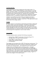
Base Station
A Research Prototype Base Station was developed which implements the
functional requirements described above. As shown in Figure 6-3, the Research
Prototype consisted of a Dell Dimension 600 MHz Pentium III running Windows
98 equipped with a high speed Internet connection. In the event of a crash, the
Mobile Unit and Base Station will communicate using wireless Cellular Digital
Packet Data (CDPD) technology over analog cellular networks. CDPD is a new
wireless Web access technology with widespread coverage in the eastern United
States. CDPD allows a direct TCP/IP link to be established between the Mobile
Unit and Base Station. Using CDPD, the Base Station is designed as a Web
Server, and the Mobile Unit reports a crash to the Server via a wireless Internet
connection. This approach allows the Base Station to monitor multiple vehicles
involved in crashes without the requirement for banks of dedicated phone lines.
When the Base Station receives a message from a Mobile Unit, the Base Station
displays the crash location and severity on a commercially available mapping
product.
Figure 6-3. Base Station: Research Prototype
The system will use Cellular Digital Packet Data (CDPD), sometimes referred to
as a Wireless IP connection, to transmit data between the Mobile Unit and the
Base Station. CDPD is a cutting edge wireless communications protocol which
31
allows direct connection of remote devices to the Internet. In addition to CDPD,
the Mobile Unit has been designed for adaptation to other wireless
communications options, including CDMA (Code Division Multiple Access) Data,
GSM (Global System for Mobile Communications), and emerging third
generation wireless protocols, e.g. GPRS (General Packet Radio Service) and
W-CDMA (Wideband Code Division Multiple Access).
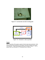
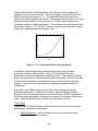
Software Implementation
The Research Prototype Base Station was implemented using the APRS-SA
Packet Radio Location Software. APRS-SA is a shareware software package
which automatically plots the location of a transmitted GPS string on maps
displayed under Street Atlas 8.0. Figure 6-4 shows a map displayed by the Base
Station running APRS-SA during a tracking test of the Mobile Unit near Rowan
University.
Figure 6-4. Sample Base Station Display
Normally the APRS-SA client software receives GPS strings from an APRS
server via the TCP/IP protocol. In setting up APRS-SA, the user is given the
option to select their APRS Server of choice. For the prototype Base Station, our
approach was to develop an APRS Server look-a-like that received messages
from the Mobile Units from a UDP port and served those messages to the APRSSA client from a TCP/IP port. The messages, which were passed to APRS-SA,
were formatted by our program to look like messages which would normally be
received via packet radio. This approach allowed the APRS-SA program to
believe that it was receiving packet radio messages when in actually it was
receiving messages from a Mobile Unit.
32
The UDP protocol was selected for the wireless communications link between
the Mobile Unit and the Base Station instead of the more typical TCP/IP. The
UDP protocol does not require verification of the transmitted message packets,
and hence is a faster protocol than TCP/IP. This approach removes the
computational burden of verification on the limited computing resources of the
Mobile Unit, and allows the Mobile Unit to transmit repeatedly to the Base Station
without having to pause after each transmission and wait for an
acknowledgement.
The Base Station software was initially written as a Perl script, and later rewritten
as a Java application. The TCP/IP port was set as 9110, and the UDP port was
9111. The code for both versions is provided as an appendix to this report.
Future Work
The long-term objective of the ACN system is to connect the Mobile Units with
existing or expanded 911 systems. However, this effort will require coordination
with existing 911 system operators and careful attention to how best to present
crash information graphically to operators who are more accustomed to receiving
voice-only calls. The Base Station developed here will provide an early
evaluation of possible 911 operator user interfaces. The Base Station may also
be suitable for limited field testing of the system for captive fleets such as the
State Police or NJDOT vehicles.
33
7. TESTING
To evaluate the performance of the ANJEL system, the Mobile Unit was
subjected to a battery of tests during development. The tests included both nonimpact vehicle tracking test as well as low-severity impact tests. This section
describes the test strategy, test procedures, test apparatus, and test results.
Tracking Test
To check the communication between the Mobile Unit and the Base Station, the
completed prototype was tested in tracking mode. In this test, the Mobile Unit
and associated antennas were mounted in a car, and the Mobile Unit was
switched to its special diagnostic-tracking mode. When in tracking mode, the
Mobile Unit automatically reads the GPS and transmits its location every second.
Note that tracking mode is a research diagnostic only: this mode will not be
included in the production prototype. During the test, the car with installed
Mobile Unit was driven on a 10-mile circuit around Rowan University. From the
continuously updated map on the Base Station, we were able to track the student
team as they drove from street to street, and were able to even identify which lot
they parked in upon their return.
Low-Severity Impact Testing Objectives
The ANJEL Mobile Unit was tested in an impact test for two purposes:
(i)
(ii)
To check if the unit can detect a crash,
To ensure the system can survive a crash.
The goal was to evaluate the performance of the Mobile Unit in low-severity
crashes. For this project, low severity was defined as that impact speed at which
the airbag would normally deploy – approximately 12-15 mph. Higher severity
crashes, such as the NHTSA full-barrier 30 mph crash tests are expected to
result in peak decelerations of 30G or higher. Although the contractual
requirements of the current project are limited to evaluation of the Mobile Unit at
low-severity crashes, it is recommended that follow-on projects test the unit in
higher-severity crash tests.
Micro-drop Test
A micro-drop tower design was chosen as the first impactor because of the
simplicity of its design and ease of fabrication. The micro-drop tower, shown in
figure 7-1, was constructed by cantilevering a rope and pulley system from the
top of the Rowan Drop Tower. The Rowan Drop Tower, normally used in aircraft
seat crash testing, allows freefall drops from heights up to 6 meters. The Mobile
Unit enclosure was fixed to a wooden platform which could be hoisted to the
34
desired drop height via a rope-pulley system. During free fall, the platform and
attached Mobile Unit was constrained by four guide cables which passed through
four eye hooks attached to the corners of the platform.
Figure 7-1. Micro-drop Tower Apparatus
Instrumentation
The fixture holding the Mobile Unit during testing was instrumented with an
external accelerometer as a check against the internal Mobile Unit
accelerometer. The major challenge was determining a location for the
accelerometer so it would not get damaged. A second concern was how the
accelerometer on a moving system would be connected to a stationary data
acquisition system. The accelerometer required a constant power source and a
cable for transmitting data back to the A/D board. The cable was mounted in a
manner to avoid tangling during the drop tests.
Experimental Setup
The accelerometer was connected to a signal-conditioning unit through the use
of an umbilical cable. The signal-conditioning unit provided the required
35
excitation voltage to the accelerometer. The signal-conditioning system also
provided signal filtering and amplification prior to input to the data-acquisition
board. To implement the data acquisition system a PC was used with the
DasyLab data acquisition software.
Procedure
The experimental procedure was drop the plate with accelerometer, from various
heights on to different surfaces at the base. The plate was dropped from three
different heights: six feet, eleven feet, and seventeen feet. Three different
densities of foam, ranging from very soft to very dense, were used for the impact
surface. A total of eighteen drops were performed. To evaluate test
repeatability, two drops were performed for each height onto each of the foams.
During testing, the accelerometer plate was pulled up to the required height, and
the data acquisition system was started. The plate was then allowed to freefall
onto the foam. The acceleration was recorded for each drop and plotted versus
time.
Results
As shown in Figure 7-2, the drop tower was able to produce realistic
accelerations when tested with the Mobile Unit enclosure. However, while the
absolute acceleration levels were realistic, the results of the test were not entirely
representative of an actual crash. For example, Figure 7-3 shows the results of a
1999 Dodge Intrepid frontal crash test. Comparison of the two types of tests
shows that while the acceleration levels are similar the pulse shapes are quite
different. This would suggest that the way the forces are applied to the test
articles differs in some manner. Moreover, in the drop test, the impact speed is
limited to a terminal velocity of approximately 20 miles per hour – which is at the
lower range of real world injury-producing automotive crashes. Consequently, a
second impactor was explored to attempt to produce more “real world” impact
conditions.
36
G’
Time (s)
Figure 7-2. Drop tower results.
Intrepid_35.Occ
Intrepid_30.Occ
Intrepid_25.Occ
0
-5
-10
G’
-15
-20
-25
-30
-35
-40
0.000
0.025
0.050
0.075
0.100
0.125
0.150
Time (s)
Figure 7-3. 1999 Dodge Intrepid crash pulses in Full-frontal barrier
collisions at 25, 30, and 35 mph impact speeds
37
Mini-Sled Impactor System
To produce higher speed impacts, a bench-scale pneumatically driven sled was
designed and evaluated for possible Mobile Unit testing. To accelerate the
Mobile Unit enclosure, the casing was mounted on a carriage placed between
two guiding rails as shown in Figure 7-4. A pneumatic cylinder was selected to
generate sufficiently high forces to rapidly accelerate the Mobile Unit at target
speeds up to 35 mph. Once the ACN unit had been accelerated to sufficiently
high speeds, it was crashed into a stationary wall at the end of the slide. The
design and construction of the required apparatus is described below:
Figure 7-4. Concept Model of the Benchscale Impactor
Air Cylinder
In the design of the impactor, the biggest challenge was discovering how to
accelerate the Mobile Unit until it reached a speed of about 35-mph. An air
cylinder was used to accomplish this task. In choosing an air cylinder there were
two selection factors: the bore size of the cylinder, and the stroke length of the
piston. In the current design, the stroke length was fixed at 12 in, and the bore
38
size was adjusted accordingly. The major factor affecting the bore size would be
the force to accelerate the load of the carriage. Using Newton’s second law
(F=ma), with an assumed Mobile Unit mass of 7lbm and an acceleration of
12454.28in/s2 (30 G’s), the required force was found to be 225.6 lbf. In other
words, the air cylinder must be able to produce a force of at least 225 lbf.
The next task was accounting for any losses in the system. The work
requirements for the pneumatic cylinder were computed as follows:
m = 7lb
V = 546.72 in s
W = Fx = 1 2 mV 2
W = 2707.453lb ⋅ in
To account for frictional and other losses in the system, a cylinder work effiency
of 50% was assumed. The process was then re-analyzed assuming polytropic
work:
= 1 .4
k
W p2v2 − p1v1
=
2
1− k
d
2π
2
110 psia 2
3πd
2707.453lb ⋅ in
=
2
d
2π
2
= 3π d 2
2
=
v
1
v
2
p
1
p
2
= 110
=
p
psia
1
v
v
1
2
k
2 1.4
2
d
2
3
110
2
π
π
∗
−
∗
d
psia
2
1 − 1.4
d = 2.475
However, in addition to accelerating the carriage up to 30g and overcoming
frictional losses inside the piston, the cylinder must also ensure that the air can
be evacuated prior to the next stroke (any backflow would prevent the process
from being polytropic, a key assumption in the analysis above). Consequently, a
larger 3-inch bore diameter cylinder was used to ensure adequacy over the test.
Figure 7-5 shows the air cylinder used for the apparatus.
39
Figure 7-5. Air cylinder with a 3” bore diameter
Despite the conservative design described above, initial testing of the apparatus
revealed insufficient acceleration of the Mobile Unit. To improve the impactor
performance, the inside of the front plate was bored out to enhance air escape
from the non-pressurized side of the cylinder. This allowed the cylinder to let out
the maximum amount of air, and completed the construction of a fast acting
cylinder.
Figure 7-6. Test stand with mounted piston
40
Figure 7-7. Rails mounted to test stand
Figure 7-8. Carriage on rail system
41
Test Stand and Rails
The test stand is one of the most integral parts of the impactor setup. It is
approximately 11 feet long, thereby allowing for 10-foot rails and a 1-foot wide
cylinder. As shown in Figure 7-7, the test stand holds the cylinder in place and
absorbs the recoil from firing. During testing, the test stand is constrained so that
the platform does not slide along the floor. Aluminum was chosen as the
material of construction. In order to ensure that the box experiences the proper
acceleration forces, it is necessary to guide and support the box with as little
interference as possible from the rails. Owing to its simplicity and ease of
operation, a dry rail system was used. For better lubrication, the rails were
polished to a smooth finish. To further reduce friction, Teflon pads were mounted
on the inside of the carriage brackets.
Carriage
As shown in Figure 7-8, the carriage is supported by two brackets on either side.
A common base connects the two brackets. This platform is approximately 12
inches long, and as wide as the rails dictate it to be. to reduce the friction
between the support brackets and the polished rails, “felt” is glued to the inside.
A wall is attached to the rear of the carriage so the ACN does not come in direct
contact with the piston rod. Moreover, at the end of the rails, there will be a wall
so the carriage will not experience a “metal on metal” collision.
Instrumentation
The data acquisition system consisted of the following components:
•
•
•
•
•
Analog Device: ADXL150 single axis accelerometer (Figure 7-9)
Metraplex Series 300 signal-conditioning system
Iotech DBK11a screw terminal card
DasyLab data acquisition software
PC Workstation
The carriage was instrumented with an ADXL150 single axis accelerometer. The
ADXL150 accelerometer was used to measure the acceleration experienced by
the Mobile Unit during the impact. This accelerometer was connected via an
umbilical cable to the Metraplex signal conditioning system. The signal
conditioning system provides power for the accelerometer and amplifies the
return signal. The output from this device will then be fed to the Iotech DBK11A
screw terminal card. This is the device that will receive the conditioned, amplified
signal, and in turn connect with the computer via a parallel port, sending the data
to DasyLab. This data was then imported into Matlab for display. Figure 7-10
shows a block diagram of the complete system.
42
Figure 7-9. Accelerometer mounted to testing plate
Data from
Accelerometer
Crash Test
Simulator
With
accompanying
Accelerometer
Power
Supply
Power to
Accelerometer
DBK11 ScrewTerminal Card
PCDaisy
Lab,
Matlab
Figure 7-10. Schematic for data acquisition
Results
After construction of the system, a series of twelve tests were conducted. Tests
were conducted with and without Teflon pads, and with and without the Mobile
Unit Enclosure. A table documenting all the tests is shown in Table 7-1. An “X”
denotes the use of the part, an “O” denotes the lack of the part.
43
Table 7-1. List of Mini-Sled Tests Performed
Trial
Teflon
Pads
ACN
Box
1
O
O
2
O
O
3
O
O
4
X
O
5
X
O
6
X
O
7
X
X
8
X
X
39
X
X
10
O
X
11
O
X
12
O
X
44
G’s
G’s
Time (s)
Time (s)
(b) With Teflon Pads.
(a) Without Teflon Pads.
Figure 7-11. Acceleration Pulses without the Mobile Unit Enclosure
G’s
G’s
Time (s)
Time (s)
(b) With Teflon pads
(a) Without Teflon Pads.
Figure 7-12. Acceleration Pulses with the Mobile Unit Enclosure
45
Graphs were obtained of the deceleration-time history of the carriage at the
impact point at the end of the rails. The first two graphs were taken without the
Mobile Unit Enclosure (Figure 7-11). The same tests were performed twice –
first with the Teflon padding, then without. These show that only about 8 g’s total
acceleration was obtained. Note that the use of Teflon pads produced only
moderate increases in peak acceleration. The procedure was then repeated with
the ACN box (figure 7-12). Figure 7-12 shows that similar results were obtained.
In all cases, peak deceleration was below 10 G.
5
0
-5
-10
-15
G’s
-20
-25
-30
-35
-40
0
0.005
0.01
0.015
0.02
0.025
0.03
0.035
0.04
Time (s)
Figure 7-13. Acceleration Pulse of the Air Piston
In addition to these impact tests performed on the rails, tests were also
performed on the air cylinder piston. Figure 7-13 shows that the peak
acceleration of the air cylinder piston was about 35 g’s. The peak was attained
early in the test when air cylinder pressure was at its highest. As the piston shaft
extended, the acceleration dropped back to zero as the cylinder air pressure
dropped. The entire event was observed to take place in approximately 35
milliseconds.
After tests on the Mobile Unit enclosure itself were completed, a test was
performed with the Rev. A Mobile Unit in place. When the Mobile Unit was
plugged into the PC and slammed into the wall, the word “CRASH” appeared on
the screen when appropriate, indicating the success of the system in detecting a
crash. Peak deceleration during the test was observed to be 9 Gs.
Future Work
Testing of the a Mini-Sled Impactor System showed the potential for improved
performance, especially in three areas:
•
Rails Modifications. If an air cushion were used to carry the system,
friction could be greatly reduced.
46
•
Carriage Modifications. Bearings and rollers/wheels should be added to
facilitate motion of the Mobile Unit.
•
Air Cylinder Modifications. To improve the speeds achieved, more air flow
should be allowed to leave the piston on the outstroke.
47
8. CONCLUSIONS
This project has developed a Low-Cost Automated Crash Notification System for
eventual field-testing on New Jersey highways. The system was developed in
response to national studies which show that nearly half of all traffic crash
fatalities occur before the crash victim reaches a trauma center. Many of these
deaths can be attributed to the inability of EMS personnel to locate and reach the
victim during the so-called “Golden Hour” after the accident when emergency
medical treatment is most effective. The goal of this project was to dramatically
reduce EMS response time by developing and testing an advanced in-vehicle
system that automatically transmits the location and severity of a crash to EMS
personnel. Specific accomplishments of the project include:
•
The project has designed, developed, and tested a low cost functional
system that combines wireless communications and Global Positioning
Systems with a network of inexpensive sensors for crash detection. The
project has developed two Mobile Unit prototypes which have been
demonstrated to communicate vehicle location to a remote Base Station
via a Wireless Web communications link.
•
The project has developed a Base Station based upon commercially
available mapping software which has been successfully demonstrated to
communicate via wireless modem with Mobile Units in the field, receive
vehicle coordinates from the Mobile Unit, and automatically indicate
Mobile Unit location on the Base Station system.
•
Two impactors were developed for testing of the Mobile Unit: (a) a Drop
Tower and (b) a Pneumatic Benchscale Impactor. Of the two the Drop
Tower was found to be the more promising. The Drop Tower was found
capable of producing up to 100 G’s and produced crash pulse shapes
which were observed to be similar to actual rigid barrier crash tests with
production passenger cars.
•
In low severity impact tests, the research team has successfully tested the
Mobile Unit at severities up to 9 G. These tesst were designed to evaluate
the survivability of the electronics to impact as well as testing the ability of
the system to detect and report collisions of this magnitude.
48
9. RECOMMENDATIONS
This project has successfully demonstrated the feasibility of a Low-Cost
Automated Crash Notification System. The performance of both a Mobile Unit
prototype and a prototype Base Station has been successfully tested in a series
of laboratory low-severity impact tests. Although system performance has shown
unusual promise, it must be emphasized that the systems tests have been
conducted solely in a controlled laboratory setting. Prior to development of a
production system, the following additional tasks are recommended:
•
Field Testing. Future work should include a second research phase
which will perform operational field testing of the ACN system. A fleet test
would evaluate the performance of the system in both crash and noncrash modes, and would provide important consumer acceptance
feedback from the motorists. A fleet of 1000 ACN-equipped cars could be
expected to incur approximately 10 collisions per year for evaluation of the
system under crash conditions. The location of the cars should be chosen
to produce a fleet mix representative of the New Jersey’s mix of urban and
rural highways. Captive fleets such as those maintained by the New
Jersey Department of Transportation or the New Jersey State Fleet would
be ideal for such a field test.
•
Higher-severity impact testing. Although the system has been
demonstrated to be crashworthy in low-severity tests, we recommend that
follow-on projects should conduct additional laboratory performance
testing of the system at the higher impact severities attainable in staged
crash tests and HyGe sled tests.
•
Integration of ACN into existing New Jersey Emergency Response
Systems. One of the most challenging and important questions
confronting deployment of an Automated Crash Notification system is
determining how to integrate an ACN system into existing 9-1-1 systems.
Follow-on research should actively consult with the representatives of the
emergency response community to address this issue.
•
Lower Cost Wireless Communication. New 3rd Generation Wireless
communications protocols will be introduced to the market in the coming
months which should be actively investigated in follow-on studies.
Currently, the Wireless Modem accounts for half the cost of the Mobile
Unit. These newer wireless protocols have the potential to tremendously
wireless communication performance and further reduce the costs of the
wireless link between the Mobile Unit and the Base Station.
49
10. REFERENCES
1. National Highway Traffic Safety Administration, 1999 Fatality Analysis
Reporting System, U.S. Department of Transportation (1999).
2. National Highway Traffic Safety Administration, “Traffic Safety Facts 1999”,
U.S. Department of Transportation (2000).
3. Thomas, S.G., “Smart cars need fewer brains and more old-fashioned
common sense”, U.S. News & World Report (February 14, 2000)
4. Champion, HR, Augenstein, JS, Cushing, B, Digges, KH, Hunt, R, Larkin, R,
Malliaris, AC, Sacco, WJ, and Siegel, JH, “Automatic Crash Notification: the
Public Safety Component of the Intelligent Transportation System”, AirMed,
(March/April 1998)
5. Preziotti, G., Kanianthra, J., and Carter, A., “Enhancing Post-Crash Vehicle
Safety through Automatic Collision Notification”, Proceedings of the 17th
International Technical Conference on the Enhanced Safety of Vehicles,
Amsterdam (June 2001)
6. Mentzer, S. Sisame User’s Manual, National Highway Traffic Safety
Administration (1999)
7. Trimble Navigation Limited, ACE II GPS System Designer Manual (June
1999)
8. Conexant Systems, Zodiac GPS Receiver Family Designers’ Guide (February
1999)
50
Appendix A:
SOURCE CODE FOR THE BASE STATION
PROTOTYPE
A.1 Base Station in Java
Function. The following stand-alone Java server received UDP messages from
the Mobile Unit and served these messages from a TCP/IP socket to an APRSSA client.
import java.net.*;
import java.io.*;
public class ACN_Server
{
public final static int MAX_PACKET_SIZE=65507;
public static void main (String args[])
{
System.out.println ("Base Station Server\n");
String hostname="localhost";
int port=8080;
byte[] buffer = new byte[MAX_PACKET_SIZE];
//*** Setup Datagram Socket.
try
{
DatagramSocket soc = new DatagramSocket (port);
DatagramPacket thePacket =
new DatagramPacket (buffer, buffer.length);
//*** Read keyboard messages and send them to the UDP Socket.
BufferedReader in = new BufferedReader (new
InputStreamReader(System.in));
while (true)
{
soc.receive (thePacket);
51
String s = new String(thePacket.getData(), 0,
thePacket.getLength());
System.out.println (thePacket.getAddress()
+ " at port " + thePacket.getPort()
+ " says " + s);
// reset the length for the next packet
thePacket.setLength(buffer.length);
}
}
catch (Exception e)
{
System.err.println (e);
}
}
}
52
A.2 Simulated Mobile Unit in Java
Function. The following code was developed to allow the Base Station to be
tested from a simulated Mobile Unit. The simulated Mobile Unit was a Java
program running on a separate PC. This program transmitted UDP messages
containing GPS coordinates to the Base Station Server.
import java.net.*;
import java.io.*;
public class Key2UDP
{
public static void main (String args[])
{
System.out.println ("Mobile Unit Simulator\n");
String hostname="150.250.105.127";
int port=8080;
// Address of ACN-Server
//*** Setup Datagram Socket.
try {
InetAddress dest = InetAddress.getByName (hostname);
System.out.println ("Destination: " + dest);
DatagramSocket soc = new DatagramSocket ();
//*** Read keyboard messages and send them to the UDP Socket.
BufferedReader in = new BufferedReader (new
InputStreamReader(System.in));
while (true)
{
String msg = in.readLine();
if (msg.equals(".")) break;
byte msgbytes[] = msg.getBytes();
DatagramPacket theOutput =
new DatagramPacket (msgbytes, msgbytes.length,
dest, port);
soc.send (theOutput);
}
}
catch (Exception e)
{
System.out.println (e);
}
}
}
53
A.3 Base Station Server in Perl
#!/usr/bin/perl
`mode COM2: BAUD=19200 PARITY=N DATA=8 RETRY=N STOP=1`;
$COUNTER = 0;
$logfile = 'C:/acn/crash.log';
$crashfile = 'c:/acn/crash.txt'; # Set to '2' when an alert happens
$nemafile = 'c:/acn/gps.nmea'; # Logs all valid NEMA with GPS data
$chr10 = chr (10);
$chr13 = chr (13);
# Takes a TCP connection, echos it back - but several now!
use IO::Socket;
use IO::Select;
open (LOGGER, ">>$logfile") or &log ('WARNING - unable to log status
msgs');
open (NMEA, ">>$nemafile") or &log ('WARNING - unable to log NEMA
string');
$listener = IO::Socket::INET->new(Proto=>'tcp', LocalPort=>'9111',
Listen=>10, Timeout=>500)
# Normal connect timeout = 60
or die ('Can not open port 9111 for listening!');
$selector = new IO::Select ($listener);
&log ("STARTUP: Listening to port 9111 TCP for APRS systems");
# Set up UDP port, Add to selector here
$udp = IO::Socket::INET->new (LocalPort => '9110', Proto => 'udp',
Reuse=>1)
or die "Can not open UDP socket";
$selector->add($udp);
&log ("STARTUP: Listening to port 9110 UDP for Alerts");
while (@consready = $selector->can_read) {
for my $connection (@consready) {
if ($connection == $listener) { # Is it a new TCP connection?
my $newconn = $connection->accept;
# Say hi to our new friend
$newconn->autoflush(1);
print $newconn "# ROWAN ECE ACN PROJECT EXPERMENTAL SYSTEM /
APRS RELAY$chr13$chr10";
$newip = $newconn->peerhost;
$port = $newconn->peerport;
$time = scalar(localtime);
&log ("INFO: TCP APRS Connection from $newip port $port");
# Add new connection to selector
54
$selector->add($newconn);
alert?
} elsif ($connection == $udp)
{ # UDP connection - possible
$connection->recv ($udpdata, 250);
# Code to verify valid alert goes here
my @lines = split ('\n', $udpdata);
for my $line (@lines) {
$line =~ s/\r//go;
system ('echo', $line, '>', 'COM2');
} # End for line of lines
if ($udpdata =~
/\$\w\wGGA,(\d\d)(\d\d)(\d[\d\.]+),(\d+.\d+),(\w),(\d+.\d+),(\w),(\d).*/
io)
{ # Begin if valid GPS data
$hour = $1; $min = $2; $sec = $3;
$lat = $4; $ns=$5;
$long = $6, $ew=$7; $quality = $8;
$ns = uc ($ns); $ew = uc ($ew);
my $ip = $udp->peerhost;
my $port = $udp->peerport;
&log ("ALERT - Alert Recieved $time from $ip port
$port");
&log ("ALERT - $ip GPS Data $lat$ns $long$ew");
&log ("ALERT - $ip GPS Data Recorded $hour:$min:$sec
GMT");
&log ("ALERT - $ip GPS Quality Indicator: $quality");
# Code to write to MS's stuff goes here...
print NMEA $udpdata;
if ($udpdata !~ /[\n\r]$/) {print NMEA "\n";}
#
open (FLE, ">$crashfile") or &log ('WARNING - unable to
trigger MS crash system via file!');
#
print FLE "2\n"; close (FLE);
# Code to alert all TCP via APRS goes here
#
if (int ($lat) != $lat)
#
{$lat = sprintf ('%02d', int($lat))
#
. sprintf('%05.2f', ($lat - int($lat)) * 100/50*30);
}
#
else {$lat = sprintf ('%07.2f', $lat * 100);}
#
if (int ($long) != $long)
#
{$long = sprintf ('%03d', int($long))
#
. sprintf('%05.2f', ($long - int($long)) *
100/50*30); }
#
else {$long = sprintf ('%08.2f', $long * 100);}
$lat = sprintf ('%07.2f',$lat);
$long = sprintf ('%08.2f',$long);
my ($sec,$min,$hour,$mday,$mon,$year,$wday,$yday,$isdst) =
gmtime(time);
$zulu = sprintf ('%02d%02d%02dz', $mday, $hour, $min);
my $string1 =
"ALERT>APZ100,TCPIP*:/$zulu$lat$ns\\$long$ew" . "'TEST EXPERIMENTAL
CRASH REP. SYS.$chr10$chr13";
55
print "\n$string1\n";
#
my $string1 = "AL3RT>APZ100,TCPIP*:!$lat$ns\\$long$ew" .
"'TEST EXPERIMENTAL CRASH REP. SYS.$chr10$chr13";
>peerhost);
my @aprssystems = $selector->can_write (1);
for my $wrcon (@aprssystems) {
if (($wrcon != $listener)&&($wrcon != $udp))
{&log ("ALERT - Notifying APRS at ", $wrcon-
print $wrcon "# ROWAN ECE ACN PROJECT EXPERMENTAL SYSTEM / APRS
RELAY$chr13$chr10";
print $wrcon $string1;
} # End if not TCP or UDP listeners
} # End For my wrcon of aprssystems
} # End if GGA NEMA string
else { &log ("WARNING - Wierd UDP string from " . $udp>peerhost. ":" . $udp->peerport);
&log ("WARNING - $udpdata");
my @aprssystems = $selector->can_write (1);
for my $wrcon (@aprssystems) {
if (($wrcon != $listener)&&($wrcon != $udp))
{&log ("WARNING - Notifying APRS at ", $wrcon>peerhost);
$udpdata =~ s/[$chr13$chr10]//go;
print $wrcon "# $udpdata$chr13$chr10";
}
} # End If
} # End For
} # End else wierd string
else { # For TCP connections
$connection->recv ($a, 1);
if ($a ne undef) { # Got one in!
$donothing = 1;
} # End if $a not equal to the undefined value
else { # Close connection
my $temp = $connection->peeraddr;
my $ip = $connection->peerhost;
my $left = $selector->count - 1 - 2 ;
&log ("INFO: Closing $ip port" , $connection->peerport);
remain.");
$selector->remove ($connection);
close $connection;
&log ("INFO: $ip:$port gone - $left APRS client(s)
} # End else close connection
} # End else character or close
} # End for
56
} # End while consready
print "\nI exited wrong - timeout waiting for users, maybe?\n";
close LOGGER;
close (NMEA);
sub log {
$time = scalar (localtime);
print "$time: @_\n";
print LOGGER "$time: @_\n";
}
57
APPENDIX B:
SISAME MODEL OF A DODGE INTREPID
The following SISAME model was used to develop the crash detection algorithm
for the Mobile Unit.
________________________________________________________________
SISAME Input File
Run Information
RunID=INTREPIDFF Title=INTREPID 1999 Full Frontal Model Weight Extraction
DimSys=Metric
DelTOut=.0001 FinTOut=.15
Model Information
VehID=INTREPID Make=DODGE
Wt=1749 IniVel=40.23
MassID=OccComp
Wt=1331.278
Model=INTREPID
Year=1999
Descr=Occupant Compartment
MassID=Engine
Wt=267.7219
Descr=Engine
MassID=Wheels
Wt=150
Descr=Front Wheels/Suspension
SprID=Occ-Bar Descr=Occ-Bar
NegMass=OccComp PosMass=.Barrier
StaType=SI SU=15410.1 ST=0
X=
0
39.47368
78.94737
197.3684
236.8421
276.3158
394.7368
434.2105
473.6842
592.1053
631.5789
671.0526
F=
0
9266.408
26253.13
114329.7
105060.7
89819.73
128010.6
152992.9
179145
317113.6
218785.2
203735.7
DynType=AM MSlp=.02251986 MMax=243.0128
SprID=Radiator Descr=Radiator
NegMass=Engine PosMass=.Barrier
StaType=SI SU=1028.647 ST=0
X=
0
32.14286
64.28571
160.7143
192.8571
225
321.4286
353.5714
385.7143
F=
0
0
0
403.2021
1381.185
2854.973
11635.49
22504.78
22504.78
DynType=AM MSlp=1.244783 MMax=22.17755
SprID=Wheels-Bar Descr=Wheels-Bar
NegMass=Wheels PosMass=.Barrier
StaType=SI SU=21114 ST=0
X=
0
39.28571
196.4286
235.7143
392.8571
432.1429
F=
0
.4361605
36.24468
76.82959
186.8221
249.3831
78.57143
275
471.4286
.4361605
186.8221
666.5682
58
118.4211
315.7895
513.1579
710.5263
61447.73
97692.63
188187
188647
157.8947
355.2632
552.6316
750
95652.23
119951.4
218022.6
173571.7
96.42857
257.1429
417.8571
0
4759.486
22504.78
128.5714
289.2857
450
0
7668.291
22683.99
117.8571
314.2857
510.7143
3.291417
186.8221
666.5682
157.1429
353.5714
550
13.88973
186.8221
666.5682
DynType=AM
MSlp=8.050754
MMax=3863.411
SprID=Firewall Descr=Firewall
NegMass=OccComp PosMass=Engine
StaType=SI SU=877.2985 ST=0 XSlk=92.60249
X=
0
21.78571
43.57143
108.9286
130.7143
152.5
217.8571
239.6429
261.4286
F=
0
0
0
0
0
0
768.7556
19880.03
38992.6
DynType=AM MSlp=0 MMax=1
65.35714
174.2857
283.2143
0
0
58105.17
SprID=Occ-Wheels Descr=Occ-Wheels
NegMass=OccComp PosMass=Wheels
StaType=SI SU=230.3747 ST=1066.072 XSlk=5.12806
X=
0
7.276681
14.55336
21.83004
36.38341
43.66009
50.93677
58.21345
72.76681
80.04349
87.32017
94.59685
F=
0
0
0
0
0
0
0
0
0
0
0
0
DynType=AM MSlp=0 MMax=1
SprID=Wheels-Eng Descr=Wheels-Eng
NegMass=Wheels PosMass=Engine
StaType=SI SU=62.11453 ST=293.0707 XSlk=21.9767
X=
0
8.851277
17.70255
44.25638
53.10766
61.95894
88.51277
97.36405
106.2153
F=
0
0
0
0
0
0
794.2044
1343.997
1632.624
DynType=AM MSlp=1.417269 MMax=420.6391
Output Information
OutClass=MassTS
Qty=AVD
Mass=*
Comments
59
26.55383
70.81022
115.0666
0
0
1632.624
87.14286
196.0714
305
0
0
76637.24
29.10672
65.49013
101.8735
0
0
0
35.40511
79.66149
123.9179
0
244.4115
1632.624
APPENDIX C:
SOURCE CODE FOR THE MOBILE UNIT PROTOTYPE
1.
A_DACN.cpp
//This program tests the A/D and outputs the value read to the
// serial port for reading with the hyper terminal
#define IBAUD0 4800/1200
// baud rate
#define IBAUD1 9600/1200
// with modem either 2400 or 1200
// without modem => 19200,9600, 4800, etc
#define TBUFSIZE 384
// size of transmit buffer
#define RBUFSIZE 384
// size of receive buffer
#define CS4 0x40C0
#define CS5 0x4100
char MODE = 4;
char NO_MODEM = 0;
char ECHO = 1;
// 8 data, no parity, 1 stop
// we don't want modem
// we do want character echo
main(){
unsigned int input,upper,lower,i;
int j,h;
int count;
char tbuf[TBUFSIZE];
// transmit buffer
char rbuf[RBUFSIZE];
// receive buffer
char buf[RBUFSIZE+1];
// dummy buffer for receiving a
//complete command
char buf2[RBUFSIZE+1];
char output[3];
char reference[16];
//allows serial port 0 to work.
#if ROM==0
reload_vec(14, Dz0_circ_int);
#endif
Dinit_z0(rbuf,tbuf,RBUFSIZE,TBUFSIZE, MODE, IBAUD0, NO_MODEM,
ECHO );
Dinit_z1(rbuf,tbuf,RBUFSIZE,TBUFSIZE, MODE, IBAUD1, NO_MODEM,
ECHO );
reference[0] = '0';
reference[1] = '1';
reference[2] = '2';
60
reference[3] = '3';
reference[4] = '4';
reference[5] = '5';
reference[6] = '6';
reference[7] = '7';
reference[8] = '8';
reference[9] = '9';
reference[10] = 'A';
reference[11] = 'B';
reference[12] = 'C';
reference[13] = 'D';
reference[14] = 'E';
reference[15] = 'F';
input=0;
for(;;){
// endless loop constantly monitoring for
// new command line
runwatch();
hitwd();
//hold value
outport(CS5+4 ,1);
//begin conversion to A/D
outport(CS4+3,0);
//wait for A/D to finish converting
for(i=0;i<1000;i++);
//read A/D
input = inport(CS4+3);
//release held value
outport(CS5+4 ,0 );
//compute hex values
upper = input/16;
lower = fmod(input,16 );
//assign hex values
output[0] = reference[upper];
output[1] = reference[lower];
output[2] = ' ';
//write value to serial port
Dwrite_z1( output, strlen(output) );
}
}
61
2.
CDPD_GPS.cpp
//This program sends data through the CDPD
//This program takes the serial data from GPS in from port 0
// and outputs it to port 1 for the CDPD to transmit.
#define IBAUD0 9600/1200
// baud rate
#define IBAUD1 9600/1200
// with modem either 2400 or 1200
// without modem => 19200,9600, 4800, etc
#define TBUFSIZE 384
// size of transmit buffer
#define RBUFSIZE 384
// size of receive buffer
char MODE = 4;
char NO_MODEM = 0;
char ECHO = 1;
// 8 data, no parity, 1 stop
// we don't want modem
// we do want character echo
main(){
int
int
char
char
char
i,j,h;
count;
tbuf[TBUFSIZE];
rbuf[RBUFSIZE];
buf[RBUFSIZE+1];
//
//
//
//
transmit buffer
receive buffer
dummy buffer for receiving a
complete command
char buf2[RBUFSIZE+1];
//allows serial port 0 to work.
#if ROM==0
reload_vec(14, Dz0_circ_int);
#endif
// communication with Dynamic C is lost when the Z1 port is
// initialized
Dinit_z0(rbuf,tbuf,RBUFSIZE,TBUFSIZE, MODE, IBAUD0,
NO_MODEM, ECHO );
Dinit_z1(rbuf,tbuf,RBUFSIZE,TBUFSIZE, MODE, IBAUD1,
NO_MODEM, ECHO );
for(;;){
runwatch();
hitwd();
// endless loop constantly monitoring
// for new command line
if( Dread_z0(buf,ENTER) != 0 ){
string terminated with CR
Dwrite_z1( buf, strlen(buf) );
62
// wait for
}
}
3.
}
crastest.cpp
//physical crash test code
//ACN Rowan University
// # define sets named constants
#define IBAUD 19200/1200
// baud rate
// with modem either 2400 or 1200
// without modem => 19200,9600, 4800, etc
#define TBUFSIZE 384
// size of transmit buffer
#define RBUFSIZE 384
// size of receive buffer
char MODE = 4;
char NO_MODEM = 0;
char ECHO = 1;
// 8 data, no parity, 1 stop
// we don't want modem
// we do want character echo
#define CS4 0x40C0
#define CS5 0x4100
#define ticks 461
//#define ticks 921
// (18.432 MHz/20)* 0.001
// (18.432 MHz/20)* 0.001
void PRT0_init(int tc);
int status;
main()
{
unsigned int input,upper,lower;
char tbuf[TBUFSIZE];
// transmit buffer
char rbuf[RBUFSIZE];
// receive buffer
int circbuffer[50];
int runningtotal;
int index;
int crash;
int i;
// declare an array coordinate of size 1 greater than buffer
char coordinate[RBUFSIZE+1];
int time_index;
int maxruntotal;
int minruntotal;
int maxruntotal_bk;
int minruntotal_bk;
char output[7];
char reference[16];
// fill reference array with some values
63
reference[0] = '0';
reference[1] = '1';
reference[2] = '2';
reference[3] = '3';
reference[4] = '4';
reference[5] = '5';
reference[6] = '6';
reference[7] = '7';
reference[8] = '8';
reference[9] = '9';
reference[10] = 'A';
reference[11] = 'B';
reference[12] = 'C';
reference[13] = 'D';
reference[14] = 'E';
reference[15] = 'F';
//runningtotal = 0;
runningtotal = 6375;
maxruntotal = runningtotal;
minruntotal = runningtotal;
status = 0x0000;
coordinate[0]='c';
coordinate[1]='r';
coordinate[2]='a';
coordinate[3]='s';
coordinate[4]='h';
coordinate[5]=' ';
coordinate[6]='\0';
PRT0_init(ticks);
// Initializes Port 1 of the Z180 for writing
Dinit_z1(rbuf,tbuf,RBUFSIZE,TBUFSIZE, MODE, IBAUD,
NO_MODEM, ECHO );
input = 0;
index = 0;
time_index = 0;
crash = 0;
for (i=0; i<50; i++)
{
circbuffer[i] = 128;
}
runwatch();
while(1)
{
hitwd();
//hold value
64
outport(CS5+4 ,1);
//begin conversion to A/D
outport(CS4+1,0);
//wait for interrupt
while(status != 0x0100);
//read A/D value
input = inport(CS4+1);
status = 0x0000;
//release held value
outport(CS5+4 ,0 );
//place algorithm here
runningtotal = runningtotal + input circbuffer[index];
if (runningtotal > maxruntotal)
{
maxruntotal = runningtotal;
}
if (runningtotal < minruntotal)
{
minruntotal = runningtotal;
}
if (time_index == 2000)
{
// Reduce values to under 255
maxruntotal_bk = maxruntotal;
minruntotal_bk = minruntotal;
maxruntotal = maxruntotal / 100;
minruntotal = minruntotal / 100;
upper = minruntotal/16;
lower = fmod(minruntotal,16 );
//assign hex values
output[0] = reference[upper];
output[1] = reference[lower];
output[2] = ' ';
upper = maxruntotal/16;
lower = fmod(maxruntotal,16 );
//assign hex values
output[3] = reference[upper];
output[4] = reference[lower];
output[5] = ' ';
65
output[6] = '\0';
//write value to serial port
Dwrite_z1( output, strlen(output) );
Dz1send_prompt();
time_index = 0;
}
if (crash == 1)
{
Dwrite_z1( coordinate, strlen(coordinate));
Dz1send_prompt();
}
maxruntotal = maxruntotal_bk;
minruntotal = minruntotal_bk;
//if( (runningtotal < 110 ) || (runningtotal > 139) )
if( (runningtotal < 5610 ) || (runningtotal > 7089) )
{
crash = 1;
}
}
circbuffer[index] = input;
index++;
time_index++;
if( index == 50 )
{
index = 0;
}
}
void PRT0_init(int load_value)
{
DI();
outport( TCR,
inport(TCR) & '\B11101110');
// inhibit TIMER0 interrupt
outport( TMDR0L, load_value
);
outport( TMDR0H, load_value >> 8);
outport( RLDR0L, load_value
);
outport( RLDR0H, load_value >> 8 );
outport( TCR,
inport(TCR) | '\B00010001');
EI();
}
#INT_VEC PRT0_VEC ISR_readAD
interrupt ISR_readAD()
{
inport(TCR);
inport(TMDR0L);
66
}
4.
status = 0x0100;
fullprog_mod.c
//ACN Rowan University
//this program is the first complete alpha prototype program for
//ACN
//Z1 writes Z0 reads
void PRT0_init(int tc);
void crashtransmission();
#define IBAUD 19200/1200
// baud rate
// with modem either 2400 or 1200
// without modem => 19200,9600, 4800, etc
#define TBUFSIZE 384
// size of transmit buffer
#define RBUFSIZE 384
// size of receive buffer
char MODE = 4;
char NO_MODEM = 0;
char ECHO = 1;
// 8 data, no parity, 1 stop
// we don't want modem
// we do want character echo
#define CS4 0x40C0
#define CS5 0x4100
#define ticks 921 // ((18.432mhz/20)* 0.001)
char buf[RBUFSIZE+1];
// dummy buffer for receiving a complete command
int status;
main(){
unsigned int input,upper,lower;
int i;
int j;
char tbuf[TBUFSIZE];
// transmit buffer
char rbuf[RBUFSIZE];
// receive buffer
int circbuffer[50];
int runningtotal;
int index;
char coordinate[RBUFSIZE+1];
status = 0x0000;
runningtotal = 0;
index = 0;
//allows serial port 0 to work.
#if ROM==0
reload_vec(14, Dz0_circ_int);
67
#endif
//initialize interrupt
PRT0_init(ticks);
//initialize serial ports
Dinit_z1(rbuf,tbuf,RBUFSIZE,TBUFSIZE, MODE, IBAUD,
NO_MODEM, ECHO );
Dinit_z0(rbuf,tbuf,RBUFSIZE,TBUFSIZE, MODE, IBAUD,
NO_MODEM, ECHO );
input = 0;
j = 0;
while(1){
runwatch();
hitwd();
//hold value
outport(CS5+4 ,1);
//begin conversion to A/D
outport(CS4,0);
//read buffer for new coordinates
if( Dread_z0(buf,ENTER) != 0 ){
while(j<RBUFSIZE+1){
coordinate[j] = buf[j];
j = j+1;
}
}
//wait for interrupt
while(status != 0x0100);
//read A/D value
input = inport(CS4);
//return status register to normal and awaiting
// the next interrupt
status = 0x0000;
//release held value
outport(CS5+4 ,0 );
//place algorithm here
runningtotal = runningtotal + input circbuffer[index];
if((runningtotal<110 ) || (runningtotal>139) ){
crashtransmission();
}
circbuffer[index] = input;
68
index++;
if (index == 50){
index = 0;
}
}
}
//this is the initialization function for the programable
// interrupt
void PRT0_init(int load_value){
DI();
outport( TCR,
inport(TCR) & '\B11101110');
// inhibit TIMER0 interrupt
outport( TMDR0L, load_value
);
outport( TMDR0H, load_value >> 8);
outport( RLDR0L, load_value
);
outport( RLDR0H, load_value >> 8 );
outport( TCR,
inport(TCR) | '\B00010001');
EI();
}
//this points the interrupt vector to the interrupt handler
#INT_VEC PRT0_VEC ISR_readAD
//this is the interrupt handler
interrupt ISR_readAD(){
inport(TCR);
inport(TMDR0L);
}
status = 0x0100;
//this function calls the CDPD and transmits the gps coordinates
void crashtransmission(){
//disable all interrupts
DI();
//wake up CDPD
outport(CS5+1,1);
//begin and continously transmit
while(1){
Dwrite_z1( buf, strlen(buf) );
}
}
69
70