1
AlliedWare PlusTM OS
Overview of | Quality of Service Features on x900-12,
x900-24, and SwitchBlade x908 Switches
Introduction
This How To Note describes the main features of QoS on switches running the
AlliedWare Plus OS. The main features include:
C613-16120-00 REV A
z
Prioritisation and marking
Right at the point of ingress into the QoS process, packets classified to particular class
maps can have values written to one or more of their associated “markers”. The markers
can be externally visible fields (DSCP value, 802.1p value) and/or internally visible fields
(bandwidth class and queue number). These markers are explained in "Packet markers" on
page 4.
z
Policing
Packets belonging to any given class map can be assigned a colour (bandwidth class) based
on whether they are inside or outside the bandwidth limits set for that class map. The
packets are marked with the colour that was applied to them, and at various points in the
QoS process, decisions on the packets' fate can be made on the basis of what colour they
have been marked with.
z
Remarking
After policing, remarking can update packets’ QoS markers depending on how well the
flow conforms to its bandwidth limits. For example, if a flow exceeds its bandwidth
requirements, QoS can update the packets’ DSCP values.
z
Per-port control over egress queue parameters
Queue lengths, scheduling process, relative weights, etc can be set on all queues on a perport basis.
z
Highly configurable default class map
All the parameters that can be set on a normal class map can also be set on the default
class map (the catch-all class map that matches all traffic that does not explicitly match any
other class map).
www.alliedtelesis.com
z
Ability to see the current state of egress queues
There are commands that enable you to see statistics relating to every egress queue on
every port.
Each of these features is discussed in much more detail later on in this document.
Contents
Introduction .............................................................................................................................................. 1
Which products and software version does this Note apply to? ................................................. 3
The process flow and methodology of the QoS system ................................................................ 3
Packet markers ................................................................................................................................. 4
Outline of the QoS processing flow ...................................................................................................
Initial mapping to an egress queue, based on 802.1p value ....................................................
Classification ......................................................................................................................................
Premarking .........................................................................................................................................
Policing ................................................................................................................................................
Limiting or remarking (dropping non-conformant packets) ...................................................
Queue shaping ..................................................................................................................................
Scheduling ..........................................................................................................................................
Details of the component processes, and how to configure them ............................................
QoS elements: policy maps, class maps, policers, matches ..................................................
Diagram of the overall QoS process flow ................................................................................
Enabling QoS globally ....................................................................................................................
Initial mapping to queue based on tag .......................................................................................
Classification ....................................................................................................................................
Premarking .......................................................................................................................................
Policing ..............................................................................................................................................
Remarking ........................................................................................................................................
Queue shaping—queue sets, RED, and tail-drop ....................................................................
Scheduling ........................................................................................................................................
5
5
6
6
7
7
8
9
10
10
11
12
12
13
13
16
22
23
27
Egress bandwidth limiting .................................................................................................................... 29
Policing Examples ...................................................................................................................................
1: Policing separate traffic types on separate ports ...............................................................
2: Policing one traffic type on combined ports .......................................................................
3: Policing one traffic type on separate ports, and another traffic type on the same
ports combined .......................................................................................................................
4: Policing combined traffic types on separate ports .............................................................
5: Policing combined traffic types on combined ports ..........................................................
30
30
32
33
35
37
Fabric QoS .............................................................................................................................................. 38
Mapping the queues in the switching instances to queues in the fabric ............................ 39
Scheduling the queues within the fabric ................................................................................... 40
Page 2 | AlliedWare Plus™ OS: Overview of QoS
Which products and software version does this
Note apply to?
z
Products: SwitchBlade x908, x900-12XT/S, and x900-24 series switches
z
Software versions: AlliedWare Plus version 5.2.1-0.1 and above
The process flow and methodology of the QoS
system
Before discussing the details of the various processes that comprise the QoS system, it is
desirable to first get a picture of what the processes are, and the order in which they are
applied to the packets passing through the system.
Therefore, this section discusses what the QoS system is really trying to do to packets, and
how it keeps track of what it has decided about any given packet.
The QoS system does the following things:
z
decides which egress queue to send a packet to
z
decides whether to drop the packet or attempt to forward it
z
updates markers in the packet for downstream devices to use
z
controls the relative priorities of the egress queues
In general, the main aim of all the processes in the QoS system is to work out which egress
queue a particular packet should be put into.
There are several factors that can affect this choice of egress queue, so packets need to be
put through several processes, so that each of the competing factors has its opportunity to
exert its influence on the final choice of egress queue.
In some cases, the system can decide to simply discard certain packets at some steps in the
process.
Additionally, the QoS system often has an obligation to update certain fields within a packet,
to indicate to downstream devices how they should deal with the packet when it gets to
them.
So, we have this multi-stage process, and the eventual fate of a packet will depend on the sum
total of the various decisions that were made about it at various stages in the process. In
order to keep track of the outcomes of those decisions, a packet needs to be marked so that
at any point in the process it is possible to know the net effect of the decisions that have been
made on it so far.
Page 3 | AlliedWare Plus™ OS: Overview of QoS
Packet markers
There are four items that are used to mark packets as they pass through the QoS system.
z
z
Two markers that are carried within fields of the packet itself:
z
802.1p: The 802.1p or User Priority field in the VLAN tag of an Ethernet frame. This
is a 3-bit number, so it can have a value in the range 0-7.
z
DSCP: The Differentiated Services Code Point within the TOS field of an IP packet
header. This is a 6-bit number, so it can have a value in the range 0-63.
Two items that are just used within the switch chip. These are not fields within the packets,
but are extra parameters that the packets carry with them as they pass through the QoS
system:
z
Bandwidth Class: This parameter can take on the values green, yellow, or red.
Essentially it is an indicator of whether the packet is deemed to have been within the
acceptable bandwidth limit set for any particular traffic flow, or whether the packet's
traffic flow had already overflowed its acceptable limit by the time this particular
packet arrived.
A value of green indicates that the flow was within the acceptable limit when the
packet arrived, a value of yellow indicates that the flow was slightly outside its
acceptable limit when the packet arrived, and a value of red means that the flow was
well outside the limit when the packet arrived.
z
Egress Queue: This indicates the egress queue that the packet is currently slated to be
placed into, if and when it finally negotiates its way through all the steps in the QoS
process and lines up in one of the queues at its eventual egress port.
Page 4 | AlliedWare Plus™ OS: Overview of QoS
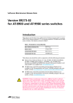
Outline of the QoS processing flow
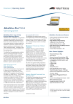
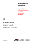
Let's look at each QoS process in the order that they are applied to a packet. The following
figure gives a quick view of the QoS features we are about to discuss.
Packet
Ingress port
Ingress
Tagged: priority mapped to queue
Untagged: mapped to default queue
Classification using ACLs
Premarking
Policing
Remarking
Limiting (dropping non-conformant)
Egress
Queue shaping
Queue emptying and egress
QoS4.eps
Initial mapping to an egress queue, based on 802.1p
value
Immediately after ingress, a VLAN-tagged Ethernet frame can be assigned to the appropriate
egress queue on the basis of the value of its VLAN Tag User Priority. This means that
incoming frames that already carry meaningful priority information can be forwarded on the
basis of that information. The mapping of the User Priority value to an egress queue is
configurable, so the administrator can decide, for example, to send frames with a Priority
value of 7 to queue 3 and frames with a Priority of 2 to queue 7.
Untagged frames don't have a VLAN Tag User Priority, so these frames can be assigned to a
default queue of the administrator's choice.
The net effect of this process is to set a value on the Egress Queue marker that the packet is
carrying.
Page 5 | AlliedWare Plus™ OS: Overview of QoS
Classification
Classification is simply a method of dividing the incoming traffic into traffic flows so that
packets of one type can be treated differently to packets of another type. To do this, you
create class maps and if desired ACLs. Incoming packets are inspected and may be classified
on a very broad range of criteria.
The classification process does not update any of the four marker values on the packet, but
does dictate the path that the packet will subsequently take through the QoS system.
Premarking
The “pre” part of premarking means this process happens before any bandwidth policing
takes place. The “marking” part refers to attaching QoS information to packets.
One possible use for this is to apply a DSCP value to a traffic stream. For example, packets
coming from a database server could require assured forwarding treatment, and so could be
marked with DSCP=18 at ingress to the switch.
Recall that packets can be marked in four ways:
z
the VLAN tag user priority
z
the Differentiated Services Code Point (DSCP)
z
the bandwidth class the packet is assigned to
z
the egress queue the packet is assigned to.
A packet can have new values assigned for each of these marking values by the premarking
process. There are two mutually exclusive methods available for premarking:
z
setting the new values explicitly for all packets that match a certain class map, or
z
looking up the mark-dscp map and applying the map’s values to the packets. The mark-dscp
map is a user-defined table that maps particular DSCP values to particular sets of 802.1p,
DSCP, bandwidth class, and egress queue values. See "Premarking" on page 13 for a table
that shows the mark-dscp map structure.
If premarking uses the mark-dscp map, there are two ways to choose the DSCP value to use
in looking up entries in the mark-dscp map:
z
use the existing DSCP value of the packet (different packets within the class map may well
have different DSCP values)
z
specify a single DSCP value that QoS will use for look-ups for all packets that match the
class map.
Whichever of these two criteria is used, the value is used to index the mark-dscp map.
Page 6 | AlliedWare Plus™ OS: Overview of QoS
Policing
Policing involves measuring the bandwidth used by a policer and comparing the measurement
to the bandwidth limits that have been set for the policer.
The policing process allocates a temporary bandwidth class value to packets. It is important
to note that the policing process does not overwrite the bandwidth class value that the
packet is already carrying around with it. Instead, an extra, temporary, bandwidth class
marker is attached to the packets.
When traffic first enters the switch, it is all marked with bandwidth class green, simply
because it has not been policed yet. Packets can be assigned a new bandwidth class at the
Premarking stage, but this is not done on the basis of actual measurement of bandwidth use.
At the policing stage, a policer's bandwidth usage is constantly monitored to see how well it
conforms to the limits set for it, and the individual packets within the flow are assigned to a
temporary bandwidth class depending on the policer's conformance to its limits at that time.
So, while a policer is still within its bandwidth limit, all the packets that have been classified to
that policer are marked with a temporary bandwidth class of green. If a policer starts to
exceed its limit, then the packets in that policer are given a temporary bandwidth class of
yellow. If it starts seriously exceeding its limits, then the packets’ temporary marking is
bandwidth class red.
The actual algorithms used to determine whether a policer is slightly exceeding its bandwidth
limit or seriously exceeding the limit are described later in this document.
Limiting or remarking (dropping non-conformant
packets)
Based on the temporary bandwidth class assigned to a packet at the policing stage, one of
two actions can be taken:
z
the packet can be dropped if it is was assigned to bandwidth class red by the policing
process, or
z
the packet can be remarked with new QoS property values.
The first of these two actions is straightforward; the user can choose to simply drop packets
if the policer exceeds the bandwidth limits set for it to the extent that packets are assigned
to bandwidth class red.
Remarking is a little more complex as it is not done solely on the basis of the bandwidth class
that the packet has been assigned to; the packet's current DSCP value, and its temporary
bandwidth class are used to determine the new values for all four QoS properties for the
packet (that is, new values for the DSCP, VLAN tag user priority, bandwidth class, and egress
queue can be specified). The new values are taken from the user-configurable policed-dscp
map.
Page 7 | AlliedWare Plus™ OS: Overview of QoS
Queue shaping
Each egress port has eight egress queues, which are numbered 0-7 with 7 being the highest
priority queue. Unfortunately, the queues are of a limited length, so packets cannot be added
to them indefinitely; if the switch is congested, the queues may fill up and no more packets
can be added. In this case, packets will inevitably be dropped from the end of the queues,
even if they are high-priority packets. Queue shaping is a general term to describe how the
egress queues can be managed to prevent the indiscriminate dropping of packets from the
tails of the egress queues.
Queue shaping can use Random Early Detection/Discard (RED). RED is a congestion
avoidance mechanism that allows some packets to be dropped before the average egress
queue exceeds the allocated maximum queue length. Lower priority packets are dropped
when severe congestion occurs, with progressively more and higher priority packets dropped
until congestion is eased. This is useful for TCP flows, because the sender will slow the rate
of transmission when it detects a packet loss. Note that using RED on UDP traffic flows is
not recommended because UDP does not reduce the rate of transmission and will simply
retransmit the dropped packets, which will add to the congestion.
The Random Early Discarding of packets from egress queues will typically be configured to
drop more packets with bandwidth class red than those with bandwidth class yellow, and to
drop even less of the packets with bandwidth class green.
RED curves are not the only queue shaping mechanism available. You can instead choose to
use a relatively simple tail-drop scheme. Using this method, you nominate a queue length at
which any further packets will be dropped. This is done for each of the three bandwidth
classes. Obviously, the queue-length threshold for bandwidth class red should be set at a
relatively low value, with the other bandwidth classes having progressively higher values.
Page 8 | AlliedWare Plus™ OS: Overview of QoS
Scheduling
In addition to managing the way in which packets can be dropped when the egress queues for
a given port start to fill up, you can also configure the method that is used to allocate
bandwidth to each of the queues to transmit packets onto the line.
There are two ways that the queues can be scheduled for transmission:
z
Strict Priority Scheduling
Higher-priority queues are emptied before any packets are transmitted from lowerpriority queues. This means that queue 7 must be totally empty before any packets from
queue 6 are transmitted, and so on.
z
Weighted Round-Robin Scheduling
The queues share bandwidth on the basis of user-defined weights. Using this method,
packets from a lower-priority queue can be transmitted even when packets are waiting in
a higher-priority queue. The weights can be configured to ensure that more packets per
second are sent from the higher-priority queues than from the lower-priority queues.
To allow for flexibility in scheduling, it is possible to use different scheduling methods for
different queues. For a given port, you can create up to three groups of egress queues, one
that uses Strict Priority Scheduling and two separate groups that each use Weighted RoundRobin Scheduling. For example, consider this case:
z
queues 7, 6 & 5 are configured to use Strict Priority Scheduling
z
queues 4, 3 & 2 are in Weighted Round-Robin group 1
z
queues 1 & 0 are in Weighted Round-Robin group 2
Queues 7, 6 & 5 will be emptied using Strict Priority, that is, queue 7 will be emptied before
any packets from queue 6 can be transmitted and queue 6 must be completely emptied
before any packets from queue 5 are transmitted.
When queues 7, 6 & 5 are all completely empty, queues 4, 3 & 2 will be emptied concurrently
based on their respective weights.
Queues 1 & 0 will be emptied only when there are no packets awaiting transmission in any of
the other queues.
Page 9 | AlliedWare Plus™ OS: Overview of QoS
Details of the component processes, and how to
configure them
QoS elements: policy maps, class maps, policers,
matches
Some aspects of QoS are configured globally, such as default mapping of CoS to egress queue.
However, most aspects are configured on a per-port basis, mostly as part of the port’s policy
map.
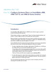
The policy map contains QoS settings for a port, and is made of class maps—one class map
for each type of traffic you want to control on the port. Class maps have match commands to
specify what traffic the class map applies to, and policers to set the bandwidth parameters for
that type of traffic. Class maps can also have other settings, such as whether to premark
traffic.
The following figure summarises these configuration elements.
Port
policy-map
class-map
match
class-map
policer
match
match
class-map
match
policer
match
qos-elements.eps
The default class map
Packets that do not match any configured class map are matched by the default class map.
These packets can still be subjected to premarking, policing and remarking. To configure
these features for the default class map, simply go into policy map class map mode for the
default class map, by using the following commands:
awplus(config-cmap)#policy-map <name>
awplus(config-pmap)#class default
Page 10 | AlliedWare Plus™ OS: Overview of QoS
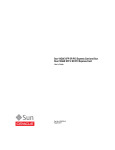
Diagram of the overall QoS process flow
The following figure summarises the QoS process flow and the commands to configure each
stage. The following sections describe the configuration in detail.
From L2 switch
Tagged packets: set egress queue
based on 802.1p, using
mls qos map cos-queue
Marker updated:
Egress Queue
Untagged packets:
set egress queue based on
mls qos queue and CoS
based on mls qos cos
Markers updated:
Egress Queue, CoS
When using trust dscp alone,
packets must have a DSCP value
for QoS to use to look up the map.
When using trust dscp and set dscp
together, set dscp specifies
the look-up value.
trust dscp (& set dscp)
set dscp, cos, etc
Use user-specified
values
Markers updated:
CoS, DSCP,
Bw Class, queue
none
Look up
mark-DSCP map
Markers updated:
CoS, DSCP,
Bw Class, queue
class-map
premarking
setting
Policing
Marker updated:
Temporary Bw Class
policed-dscp-transmit
policer
exceed-action
setting
Look up
policed-DSCP map
Markers updated:
CoS, DSCP,
Bw Class, queue
Routing
Red Curves
Egress Queuing
drop
Drop
red
packets
green and yellow packets
QoS1.eps
Page 11 | AlliedWare Plus™ OS: Overview of QoS
Enabling QoS globally
Before configuring QoS, you need to enable it by entering the following command in global
configuration mode:
awplus(config)#mls qos enable
Initial mapping to queue based on tag
When packets arrive at a port, they are assigned to an egress queue. This is done by the
switch associating an egress queue marker with the packet. For tagged packets, the switch
decides the initial queue setting by looking at the packet’s CoS value (802.1p User Priority
field). For untagged packets, there is a default queue setting, which you can change.
Of course, this is just an initial egress queue value—the QoS processing can change it at the
Premarking (page 13) or Remarking (page 22) stages.
Tagged
packets
For tagged packets, the default mapping of packet CoS value to egress queue is:
CoS:
0
1
2
3
4
5
6
7
Queue:
2
1
1
3
4
5
6
7
To change this mapping for a CoS value, enter the following command in global configuration
mode:
awplus(config)#mls qos map cos-queue <cos> to <queue>
You need to enter this command for every CoS that you want to re-map.
To see the mapping, use the following command:
awplus#show mls qos maps cos-queue
Untagged
packets
For untagged packets, the switch determines the queue by looking at the value of the mls
qos queue command. This is an interface-mode command, so the queue is set on a per-port
basis. The default value is 2.
To change this, first enter interface mode for the desired port and then specify the desired
queue number. Use the following commands:
awplus(config)#interface <port-number>
awplus(config-if)#mls qos queue <0-7>
For example, to set the initial queue to 5 for untagged packets received on port1.0.1, use the
commands:
awplus(config)#interface port1.0.1
awplus(config-if)#mls qos queue 5
Untagged packets are also assigned a CoS value, 0 by default. To change this, first enter
interface mode for the desired port and then specify the desired CoS. Use the following
commands:
Page 12 | AlliedWare Plus™ OS: Overview of QoS
awplus(config)#interface <port-number>
awplus(config-if)#mls qos cos <0-7>
The value you change the CoS to is not used to look up the initial egress queue setting; the
mls qos queue command still determines the queue for untagged packets.
Classification
The process of assigning packets to class maps requires a two stage configuration.
First, create a class map by entering the following command:
awplus(config)#class-map <name>
Then, specify the parameters for classifying traffic, by using the match command. You can
match on an ACL or on a number of other parameters, as the following table shows:
Match command parameter
What it matches on
access-group
IP or MAC hardware ACL
cos
Class of Service (802.1p value)
eth-format
Ethernet format
inner-cos
Inner CoS
inner-tpid
Inner Tag Protocol Identifier
inner-vlan
Inner VLAN ID
ip-dscp
IP DSCP value
ip-precedence
IP precedence value
mac-type
MAC type
protocol
Protocol
tcp-flags
TCP flags
tpid
Tag Protocol Identifier
vlan
VLAN ID
For detailed information about ACLs and the match commands, see the Note How To
Configure Hardware Filters on SwitchBlade x908, x900-12XT/S, and x900-24 Series Switches.
Premarking
Premarking happens after ingress, before the traffic has been policed.
There are two mutually exclusive methods available for premarking:
z
setting the new values explicitly for all packets that match a certain class map, or
z
using the mark-dscp map to apply new values to the packets.
Page 13 | AlliedWare Plus™ OS: Overview of QoS
Setting new values explicitly
To explicitly set new values for a particular class map, first create the class map (if necessary),
by entering the following command:
awplus(config)#class-map <name>
Then simply enter the following commands:
awplus(config)#policy-map <name>
awplus(config-pmap)#class <name>
awplus(config-pmap-c)#set cos <0-7>
awplus(config-pmap-c)#set queue <0-7>
awplus(config-pmap-c)#set bandwidth-class {green|yellow|red}
awplus(config-pmap-c)#set dscp <0-63>
You can set one or more of the above values. The effect is that all packets that match the
class map and policy map are marked with the values specified with these commands.
Using the mark-dscp map
The data structure that drives the premarking process is the mark-dscp map. This is a single
global table which can be thought of as a table of 64 rows—one row for each DSCP number.
In each cell of the table there are four new marker values that will be applied to packets:
802.1p, DSCP, bandwidth class and egress queue. The following table shows the structure of
the mark-dscp map.
DSCP
0
New marker values
802.1p = ...
new-dscp = ...
new-bandwidth-class = ...
new-queue = ...
1
802.1p = ...
new-dscp = ...
new-bandwidth-class = ...
new-queue = ...
2
802.1p = ...
new-dscp = ...
new-bandwidth-class = ...
new-queue = ...
.
.
.
63
802.1p = ...
new-dscp = ...
new-bandwidth-class = ...
new-queue = ...
Page 14 | AlliedWare Plus™ OS: Overview of QoS
Note that there is just a single mark-dscp map for the whole switch—separate class maps do
not have separate mark-dscp maps.
The configuration required to use the mark-dscp map is a little more complex than the
configuration for setting the values explicitly.
1. First, write entries into the mark-dscp map table.
This is a matter of specifying the DSCP, CoS, queue, and/or bandwidth class to associate
with the given pair of DSCP and bandwidth class values. To do this, enter the command:
awplus(config)#mls qos map mark-dscp <0-63> to [new-dscp <0-63>] [new-cos
<0-7>] [new-queue <0-7>] [new-bandwidth-class {green|yellow|red}]
Use this command to populate those entries of the map that you will be using. For
example, to ensure that traffic that arrives with a DSCP of 34 gets marked to bandwidth
class green, queue 4 and CoS 4, enter the command:
awplus(config)#mls qos map mark-dscp 34 to new-cos 4 new-queue 4
new-bandwidth-class green
In this example, we do not change the DSCP value—it stays as 34.
2. Set the class map to use the mark-dscp map.
Enter the commands:
awplus(config)#policy-map <name>
awplus(config-pmap)#class <name>
awplus(config-pmap-c)#trust dscp
The trust dscp command indicates that this class map will use the mark-dscp map for premarking.
Note that you can’t use the command trust dscp at the same time as the commands set
cos, set queue, or set bandwidth-class. This is because you can’t combine using the
mark-dscp map with explicitly setting premarking values.
3. Decide how the class map will choose the DSCP value to use in looking up entries in the
mark-dscp map.
There are two choices:
z
use the DSCP value that is present in each packet. This means that values marked into
a packet will depend on the DSCP value already present in the packet at ingress.
This choice requires no further configuration—the default behaviour is to use the
DSCP value present in each packet.
z
specify a single DSCP value that QoS will use for look-ups for all packets that match
the class map.
To configure this choice, use the set dscp command.
Note that the meaning of the set dscp command changes when you use the command
trust dscp on a class map. When trust dscp has been configured, set dscp specifies
the DSCP value for QoS to use to perform look-ups into the mark-dscp map. If trust
dscp has not been configured on the class map, the set dscp command specifies the
DSCP value that will be marked into all packets that match the class map (as described
in "Setting new values explicitly" on page 14).
Page 15 | AlliedWare Plus™ OS: Overview of QoS
Example
For the class map called “example”, if you want to take all traffic with a DSCP of 34, 36 or 38
and premark it to CoS 4, queue 4; CoS 5, queue 5; and CoS 6, queue 6 respectively, then
enter the following commands:
awplus(config)#mls qos map mark-dscp 34 to new-cos 4 new-queue 4
awplus(config)#mls qos map mark-dscp 36 to new-cos 5 new-queue 5
awplus(config)#mls qos map mark-dscp 38 to new-cos 6 new-queue 6
awplus(config)#policy-map example
awplus(config-pmap)#class example
awplus(config-pmap-c)#trust dscp
If instead you want to treat all traffic in the class map as if it had a DSCP of 34, enter the
following commands:
awplus(config)#mls qos map mark-dscp 34 to new-cos 4 new-queue 4
new-bandwidth-class green new-dscp 34
awplus(config)#policy-map example
awplus(config-pmap)#class example
awplus(config-pmap-c)#trust dscp
awplus(config-pmap-c)#set dscp 34
Policing
Policing is the process of counting the number of packets that the switch processes and
determining their level of conformance with their bandwidth limits. The AlliedWare Plus OS
enables you to police ports and different types of traffic separately or in combination.
Policing is performed on a per-policer basis for a class map. Policers are one of:
z
“ordinary” policers, which count the amount of traffic in a single class map in a single policy
map on a single port
z
aggregate policers, which combine the traffic belonging to a given class map across every
policy map and port that use that class map.
Both ordinary and aggregate policers can be either single-rate or twin-rate. With the
AlliedWare Plus OS, you explicitly select whether to use a single-rate or twin-rate policer.
The following sections summarise the policing options, and tell you how to configure them.
For details of the policer algorithms, see the Advanced QoS White Paper in the White Papers
library at www.alliedtelesis.com/resources/literature/literature.aspx?id=3.
For configuration examples with ordinary and aggregate policers, see "Policing Examples" on
page 30.
Page 16 | AlliedWare Plus™ OS: Overview of QoS
Applying ordinary policers to class maps
Ordinary policers are used when policing traffic in a single class map in a single policy map on
a single port. You create them in policy map class configuration mode, which means they are
attached to that policy map and class map at the time they are created. They do not have a
name, because they are identified by the policy map and class map.
The following commands give an example of a single-rate policer that monitors VLAN 2
traffic in the class map called “vlan2” in the policy map called “vlan2” on port 1.0.20:
awplus(config)#class-map vlan2
awplus(config-cmap)#match vlan 2
awplus(config-cmap)#policy-map vlan2
awplus(config-pmap)#class vlan2
awplus(config-pmap-c)#police single-rate 10000 512 1024 exceed-action drop
awplus(config-pmap-c)#interface port1.0.20
awplus(config-if)#service-policy input vlan2
Applying aggregate policers to class maps
Aggregate policers are used when policing traffic across multiple class maps, policy maps or
ports. You create them in global configuration mode and then attach them to the required
class maps. They are identified by a name.
The following commands give an example of a single-rate aggregate policer that has a CIR of
10Mbps with a CBS of 512 bytes and PBS of 1024 bytes. The aggregator policer operates on
any traffic arriving on ports 1.0.1 and 1.0.2 with a source address of 192.168.x.x or
172.20.1.x.
awplus(config)#access-list 3001 permit ip 192.168.0.0/16 any
awplus(config)#access-list 3002 permit ip 172.20.1.0/24 any
awplus(config)#mls qos aggregate-police examplePolicer
single-rate 10 512 1024 exceed-action drop
awplus(config)#class-map cmap1
awplus(config-cmap)#match access-group 3001
awplus(config)#class-map cmap2
awplus(config-cmap)#match access-group 3002
awplus(config)#policy-map pmap1
awplus(config-pmap)#class cmap1
awplus(config-pmap-c)#police aggregate examplePolicer
awplus(config-pmap)#class cmap2
awplus(config-pmap-c)#police aggregate examplePolicer
awplus(config)#interface port1.0.1-1.0.2
awplus(config-if)#service-policy input pmap1
To see the settings of aggregate policers, use the command:
awplus#show mls qos aggregate-policer
Page 17 | AlliedWare Plus™ OS: Overview of QoS
Single-rate policing
Both ordinary and aggregate policers can be single-rate. Single-rate policing uses three
parameters:
z
average bandwidth (in kbps)
z
minimum burst size (in bytes)
z
maximum burst size (in bytes)
With this combination, the algorithm used to determine the temporary bandwidth class to
assign to a packet is:
If the data rate for the policer is below the average bandwidth, or is slightly above the
average bandwidth, but the accumulation of total bits that have exceeded the average
bandwidth has not yet reached the minimum burst size, then the bandwidth class is green.
If the data rate for the policer is above the average bandwidth, and the accumulation of
total bits that have exceeded the average bandwidth has exceeded the minimum burst size
but not yet reached the maximum burst size, then the bandwidth class is yellow.
If the data rate for the policer is above the average bandwidth, and the accumulation of
total bits that have exceeded the average bandwidth has exceeded the maximum burst
size, then the bandwidth class is red.
For a more detailed explanation of the algorithm, see the Advanced QoS White Paper in the
White Papers library at www.alliedtelesis.com/resources/literature/literature.aspx?id=3.
An example of configuring a policer to do single-rate policing would be:
awplus(config-pmap-c)#police single-rate <average-bandwidth>
<minimum-burstsize> <maximum-burstsize>
exceed-action {drop|policed-dscp-transmit}
An exceed action of drop means that the switch simply drops red packets. An exceed action
of policed-dscp-transmit means that the switch remarks packets after policing.
Page 18 | AlliedWare Plus™ OS: Overview of QoS
Twin-rate policing
Both ordinary and aggregate policers can be twin-rate. Twin-rate policing uses four
parameters:
z
minimum bandwidth (in kbps)
z
maximum bandwidth (in kbps)
z
maximum burst size (in bytes)
z
minimum burst size (in bytes)
With this combination, the algorithm used to determine the temporary bandwidth class to
assign to a packet is:
If the data rate for the policer is below the minimum bandwidth, or is slightly above the
minimum bandwidth, but the accumulation of total bits that have exceeded the minimum
bandwidth has not yet reached the minimum burst size, then the bandwidth class is green.
If the data rate for the policer is above the minimum bandwidth, and the accumulation of
total bits that have exceeded the minimum bandwidth has exceeded the minimum burst
size, or if the data rate is above the maximum bandwidth, and the accumulation of total
bits that have exceeded the maximum bandwidth has not yet reached the maximum burst
size, then the bandwidth class is yellow.
If the data rate for the policer is above the maximum bandwidth, and the accumulation of
total bits that have exceeded the maximum bandwidth has exceeded the maximum burst
size, then the bandwidth class is red.
For a more detailed explanation of the algorithm, see the Advanced QoS White Paper in the
White Papers library at www.alliedtelesis.com/resources/literature/literature.aspx?id=3.
An example of configuring a policer to do twin-rate policing would be:
awplus(config-pmap-c)#police twin-rate <minimum-bandwidth>
<maximum-bandwidth> <minimum-burstsize> <maximum-burstsize>
exceed-action {drop|policed-dscp-transmit}
Page 19 | AlliedWare Plus™ OS: Overview of QoS
Counting policed packets
To see the count of policed packets:
1. Turn on the QoS counters enhanced mode by entering global configuration mode and
using the command:
awplus(config)#platform enhancedmode qoscounters
2. Restart the switch
3. Return to privileged exec mode and use the command:
awplus#show mls qos interface <name> policer-counters
Counting packets for ordinary policers
For each class map, the output shows the total (aggregate) number of bytes, and the number
of bytes of each colour. It also shows the number of bytes dropped by the policer. Dropped
bytes will equal red bytes if the policer has an exceed action of drop, otherwise it will always
be zero. That is, the dropped bytes counter only counts the packets that are dropped by the
policer, not packets that are dropped by later mechanisms such as RED curves.
The following figure shows output for the example from "Applying ordinary policers to class
maps" on page 17.
Interface:
Class-map:
Aggregate Bytes:
Green Bytes:
Yellow Bytes:
Red Bytes:
Dropped Bytes:
Class-map:
Aggregate Bytes:
Green Bytes:
Yellow Bytes:
Red Bytes:
Dropped Bytes:
Page 20 | AlliedWare Plus™ OS: Overview of QoS
port1.0.20
default
0
0
0
0
0
vlan2
0
0
0
0
0
Counting packets for aggregate policers
If a packet is processed by an aggregate policer, it is counted in the output for every port that
the aggregate policer applies to, not just for the port that received the packet.
The following figure shows output for the example from "Applying aggregate policers to class
maps" on page 17.
For port1.0.1:
Interface:
Class-map:
Aggregate Bytes:
Green Bytes:
Yellow Bytes:
Red Bytes:
Dropped Bytes:
Aggregate name:
Class-map:
Aggregate Bytes:
Green Bytes:
Yellow Bytes:
Red Bytes:
Dropped Bytes:
port1.0.1
default
0
0
0
0
0
examplePolicer
cmap1 cmap2 (port1.0.1)
cmap1 cmap2 (port1.0.2)
0
0
0
0
0
For port1.0.2:
Interface:
Class-map:
Aggregate Bytes:
Green Bytes:
Yellow Bytes:
Red Bytes:
Dropped Bytes:
Aggregate name:
Class-map:
Aggregate Bytes:
Green Bytes:
Yellow Bytes:
Red Bytes:
Dropped Bytes:
Page 21 | AlliedWare Plus™ OS: Overview of QoS
port1.0.2
default
0
0
0
0
0
examplePolicer
cmap1 cmap2 (port1.0.1)
cmap1 cmap2 (port1.0.2)
0
0
0
0
0
Remarking
Remarking happens after the traffic has been policed. It sets the packet’s QoS markers
depending on how well the flow conforms to its bandwidth limits.
Remarking is performed by looking up the policed-dscp map and assigning values to the four
markers (802.1p, DSCP, egress queue, and bandwidth class). The policed-dscp map is similar
to the premarking mark-dscp map, except that the new values can also depend on the
temporary bandwidth class from the policing stage. The following table shows the map
structure.
Bandwidth class Green
Yellow
Red
802.1p = ...
802.1p = ...
802.1p = ...
new-dscp = ...
new-dscp = ...
new-dscp = ...
DSCP
0
new-bandwidth-class = ... new-bandwidth-class = ... new-bandwidth-class = ...
1
new-queue = ...
new-queue = ...
new-queue = ...
802.1p = ...
802.1p = ...
802.1p = ...
new-dscp = ...
new-dscp = ...
new-dscp = ...
new-bandwidth-class = ... new-bandwidth-class = ... new-bandwidth-class = ...
2
new-queue = ...
new-queue = ...
new-queue = ...
802.1p = ...
802.1p = ...
802.1p = ...
new-dscp = ...
new-dscp = ...
new-dscp = ...
new-bandwidth-class = ... new-bandwidth-class = ... new-bandwidth-class = ...
new-queue = ...
new-queue = ...
new-queue = ...
802.1p = ...
802.1p = ...
802.1p = ...
new-dscp = ...
new-dscp = ...
new-dscp = ...
.
.
.
63
new-bandwidth-class = ... new-bandwidth-class = ... new-bandwidth-class = ...
new-queue = ...
new-queue = ...
new-queue = ...
To add values to the policed-dscp map, enter the command:
awplus(config)#mls qos map policed-dscp <0-63> [bandwidth-class {green|
yellow|red}] to [new-dscp <0-63>] [new-cos <0-7>] [new-queue <0-7>]
[new-bandwidth-class {green|yellow|red}]
To set QoS to remark values, specify an exceed action of policed-dscp-transmit in the
policer. Do this by entering one of the commands:
awplus(config-pmap-c)#police single-rate <average-bandwidth>
<minimum-burstsize> <maximum-burstsize>
exceed-action policed-dscp-transmit
awplus(config-pmap-c)#police twin-rate <minimum-bandwidth>
<maximum-bandwidth> <minimum-burstsize> <maximum-burstsize>
exceed-action policed-dscp-transmit
Although the keyword is named exceed-action, setting it to policed-dscp-transmit
makes QoS remark all matching traffic, not just excessive traffic.
Page 22 | AlliedWare Plus™ OS: Overview of QoS
Queue shaping—queue sets, RED, and tail-drop
A queue set defines how the switch determines what traffic to drop when a port’s queues
become congested. The queue set applies to one or more of the port’s queues, and specifies
the queue size thresholds at which the port starts to drop traffic from that queue.
You can use up to four different queue sets across the switch.There are two steps involved in
configuring queue sets:
1. configure the queue set parameters
2. apply the queue set to the desired port
There are two options for how each queue set drops excess traffic:
z
random-detect mode
z
tail-drop mode
In random-detect mode, the switch uses RED to shape queues. In tail-drop mode, the switch
simply drops excess traffic from the end of queues. Both modes are color-aware—you can
configure different thresholds for different bandwidth classes.
The following sections describe how to configure random-detect and tail-drop mode, but
first you need to consider the default settings.
Default
settings
If you do not configure queue shaping:
z
10/100/1000M ports use tail-drop mode with settings from queue set 1 (which gets a
default description of “1G Defaults”)
z
10G ports use tail-drop mode with settings from queue set 2 if there are also 1G ports
present, or otherwise settings from queue set 1 (the used queue set gets a default
description of “10G Defaults”)
Don’t customise the default queue sets unless you want to change the settings on
all ports of that type.
You can check which are the default queue sets and their current settings, by using the
command:
awplus#show mls qos queue-set
The following table shows the values for the default queue set for each port speed. These
settings apply to each egress queue and each bandwidth class—green, yellow and red traffic
all have the same values. The unused queue sets are empty, so all their values are 0.
Port speed
Setting
Value
1G
Minimum threshold
100 KB
Maximum threshold
125 KB
Drop probability
50%
Averaging factor
9
Page 23 | AlliedWare Plus™ OS: Overview of QoS
Port speed
Setting
Value
10G
Minimum threshold
1 MB
Maximum threshold
1 MB
Drop probability
50%
Averaging factor
9
Note that by default ports only use the maximum threshold, because they are in tail-drop
mode. The other settings are random-detect mode settings. Having defaults means that you
can change to random-detect mode without having to configure a queue set (see "Applying
RED curves to ports" on page 25).
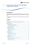
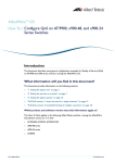
Random-detect mode—using RED
What RED
curves are
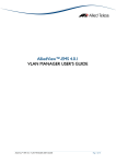
The fundamental entity in the switch’s RED curve structure is a single set of minimum
threshold—maximum threshold—drop probability values. These three values define a
“curve” such as the one shown in the following figure.
100%
Drop Probability
Drop
0%
Minimum
threshold
Maximum
threshold
QoS2.eps
z
Minimum threshold defines the length that the queue must reach before the packets
start being dropped.
z
Maximum threshold defines the length that the queue must reach before the shaper
stops dropping randomly, and just drops all further packets.
z
Drop probability defines the percentage of packets that are being dropped at the point
when the length of the queue reaches the maximum threshold value. Effectively, the drop
probability defines how quickly the rate of dropping packets must increase as the queue
length grows from the minimum threshold to the maximum threshold.
Page 24 | AlliedWare Plus™ OS: Overview of QoS
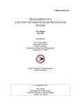
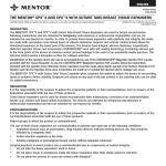
These fundamental curves are collected into RED curve groups. A group is a collection of
three curves, one for each of the three possible bandwidth classes, as shown in the following
figure.
100%
Drop 3
Drop 2
Drop 1
Drop
Probability
%
BW
Class 3
BW
Class 2
BW
Class 1
0%
Start 3
Stop 3
Start 2
Stop 2
Start 1
Stop 1
MAX queue length
Queue Length (bytes)
QoS3.eps
Additionally, one other parameter is defined on each RED curve group. This parameter is the
averaging factor. The averaging factor influences how the queue length is calculated. If the
averaging factor is 0, then the queue length value that the shaper uses in its calculation of
whether a certain packet should be dropped is the exact current length of the queue. But, if
you increase the averaging factor, then the shaper starts calculating an average length of the
queue over a certain time period, and uses this averaged value in its “should-I-drop-thepacket” calculation.
Applying
RED curves
to ports
To apply a set of RED curves to the egress queues on a given port, use the commands:
awplus(config)#interface <interface-name>
awplus(config-if)#mls qos queue-set <1-4> random-detect
If you enter this command without configuring the RED curve settings (see "Configuring RED
curve settings" on page 25), the switch uses the default queue set values. These are described
in "Default settings" on page 23.
Configuring
RED curve
settings
RED curve groups are defined in queue sets, so you can have up 4 different sets of RED
behaviour on the switch.
The commands for configuring the queue sets start with:
awplus(config)#mls qos queue-set <1-4> ...
After this, you can use the command to configure the averaging factor, the thresholds and the
drop probability. You can configure the queue-set parameters for all 8 egress queues, or for
any subset of the egress queues. Configuring a subset lets you configure different queue
shaping settings for different queues on a port.
Page 25 | AlliedWare Plus™ OS: Overview of QoS
Specifying which queues to act on
To specify which queues to configure, use the optional queues parameter:
awplus(config)#mls qos queue-set <1-4> queues ...
Specify the desired queues as a space-separated list. For example:
awplus(config)#mls qos queue-set <1-4> queues 1 3 4 ...
To configure all queues, leave out the queues parameter.
If you do not configure RED curve settings on all the queues in a queue set, the unconfigured
queues use the default settings—see page 23.
Specifying the thresholds
To specify the maximum and minimum thresholds for each bandwidth class, use the
command:
awplus(config)#mls qos queue-set <1-4> [queues <list>] threshold
<minimum-green-threshold> <maximum-green-threshold>
<minimum-yellow-threshold> <maximum-yellow-threshold>
<minimum-red-threshold> <maximum-red-threshold>
Each threshold is a value from 1-16000000 bytes.
Specifying the drop probability
To specify the drop probability for each bandwidth class, use the command:
awplus(config)#mls qos queue-set <1-4> [queues <list>]
drop-probability <green-drop-prob> <yellow-drop-prob> <red-drop-prob>
Each drop probability is a value from 0-15. The drop probability is 100% for a setting of 0 and
halves for each integer value increase. The following table shows probability values for drop
values of 0 to 7.
Drop value
0
1
2
3
4
5
% drop probability
100%
50%
25%
12.5%
6.25%
3.125% 1.562
6
7
...
0.781
...
Specifying the averaging factor
Dropping is based on the average queue length, which is calculated as:
New Average Queue Length =
n
n
(1 - 1/(2 )) * (Current Average Queue Length) + 1/(2 ) * (Current Queue Length)
where n is the averaging factor. If n is small, the average queue length follows the actual
queue length quickly and is more likely to cause global TCP synchronisation. A large value for
n means the average queue length follows the actual queue length slowly. This may prevent
global TCP synchronisation, but will drop more packets. The recommended averaging factor
is 9.
Page 26 | AlliedWare Plus™ OS: Overview of QoS
To specify the averaging factor, use the command:
awplus(config)#mls qos queue-set <1-4> [queues <list>]
averaging-factor <0-15>
Tail-drop mode
By default, ports use tail-drop mode and the default queue-set for that port type (see
"Default settings" on page 23). If you need to explicitly set a port to tail-drop mode, or if you
want to change the queue-set, use the commands:
awplus(config)#interface <interface-name>
awplus(config-if)#mls qos queue-set <1-4> taildrop
Tail-drop mode uses the same command as random-detect mode to set the maximum and
minimum thresholds for each bandwidth class:
awplus(config)#mls qos queue-set <1-4> [queues <list>] threshold
<minimum-green-threshold> <maximum-green-threshold>
<minimum-yellow-threshold> <maximum-yellow-threshold>
<minimum-red-threshold> <maximum-red-threshold>
However, when a queue-set is applied to a port for tail-drop mode, only the maximum
thresholds are used. The minimum thresholds are ignored. Any settings for averaging factor
and drop probability are also ignored.
Tail-drop mode results in the following actions:
z
If the green maximum threshold is exceeded, all packets will be dropped.
z
If the yellow maximum threshold is exceeded, all yellow and red packets will be dropped.
z
If the red maximum threshold is exceeded, all red packets will be dropped.
Scheduling
On each port, you can allocate the eight queues to the following three scheduling groups:
z
priority-queue—a group of queues that use strict priority scheduling
z
wrr-group 1—a group of queues that use weighted round robin (wrr) scheduling. Packets
are only transmitted from these queues if all queues in the priority-queue group are empty.
z
wrr-group 2—a second group of queues that use weighted round robin scheduling. Packets
are only transmitted from these queues if all queues in the priority-queue group and in
the wrr-group 1 are empty.
You can also configure egress rate limits for each queue, and limit how much of the port’s
packet buffer the queue can use. This last point is particularly important because it stops lowpriority queues from using up the whole packet buffer and thereby starving high-priority
queues.
The following sections describe how to configure all these aspects of scheduling. To configure
scheduling, first enter interface configuration mode for the desired port or ports.
Page 27 | AlliedWare Plus™ OS: Overview of QoS
Strict priority
scheduling
Then, to set queues to use strict priority scheduling, use the command:
priority-queue <queue-list>
Specify the queues as a space-separated list. For example, to put queues 3, 5, and 6 into the
strict-priority group of queues, use the command:
awplus(config-if)#priority-queue 3 5 6
Weighted
round robin
To put queues into one of the weighted round robin groups, use the command:
wrr-queue group <1-2> weight <6-255> queues <queue-list>
This configures a set of queues in the wrr1 or wrr2 group of queues, and sets their weights in
that group. The weight specifies the number of bytes transmitted from the queue in
proportion to the values for other queues in the same wrr group. For example, a queue with
a weight of 30 would transmit twice as many bytes as a queue with a weight of 15.
To put queues 2 and 7 into the wrr1 group, and give them a weight of 30 in that group, use
the command:
wrr-group 1 weight 30 queues
2 7
To put queue 5 into the wrr1 group, and give it a weight of 15 in that group, use the
command:
awplus(config-if)#wrr-group 1 weight 15 queues 5
Egress rate
limits
It is also possible to set an egress rate limit on a queue, using the command:
wrr-queue egress-rate-limit <bandwidth> queues <queue-list>
You can specify bandwidth in kilobits (e.g. 2000 or 2000k), megabits (e.g. 2m), or gigabits (e.g.
2g).
Although this command begins with the keyword wrr-queue, you can use it to configure
queues that are members of the strict-priority group of queues.
For more information, see "Egress bandwidth limiting" on page 29.
Packet buffer
pool
Each port has a dedicated pool of packet buffers that the egress queues use for queuing
packets. Theoretically, any one of the queues on a given port could use up that port's whole
buffer pool, although there is a mechanism in place to prevent this. If the mechanism did not
exist, a single queue could use the whole buffer pool, for example, if a port were
oversubscribed by a high-bandwidth high-priority stream and a high-bandwidth low-priority
stream. The high-priority stream would get more access to the egress bandwidth than the
low-priority stream, so the queue holding the low-priority traffic would grow progressively
longer. In the end, the low-priority stream would consume the entire buffer pool on the port,
thereby starving the high-priority stream of any packet-queuing resource. This would be
highly undesirable.
To avoid this problem, there is a limit on the percentage of the available buffer pool that any
given queue can consume. By default, each queue is limited to 12%, but you can change this
by using the following command:
wrr-queue queue-limit <1-100> <1-100> <1-100> <1-100> <1-100> <1-100>
<1-100> <1-100>
Page 28 | AlliedWare Plus™ OS: Overview of QoS
The first of these numbers is the percentage limit for queue 0, the second number is the limit
for queue 1, and so on.
For example, to give queue 0 less of the buffer space and queues 3 and 4 more, you could use
the command:
wrr-queue queue-limit 6 12 12 17 17 12 12 12
You can use this command to configure queues that are members of the strict-priority group
of queues, even though it begins with the keyword wrr-queue.
Viewing
queue
settings
To see the configured settings for each queue, use the command:
awplus#sh mls qos interface
Egress bandwidth limiting
The total bandwidth that can be transmitted from a set of egress queues on a port is
configurable using the interface mode command:
awplus(config-if)#egress-rate-limit <bandwidth-limit>
This means that the maximum bandwidth is not necessarily set for the port as a whole, but
for a set of the egress queues on the port.
The bandwidth limits can only be specified in multiples of 650 kbps. Whatever value you
configure will be rounded up to the nearest multiple of 650 kbps.
It is important to understand the relationship between a queue’s wrr-queue egress-ratelimit command and a port’s egress-rate-limit command. These two commands actually
control two different aspects of the egress scheduling process.
The model to consider is this: the process of putting packets onto the wire “pulls” packets
out of egress queues and puts them out the port. However, the queues can resist a “pull” and
effectively tell the “pulling” process, “sorry, I have hit my bandwidth limit and cannot give you
any packets right now”.
The port’s egress-rate-limit command sets the rate at which the port “pulls” packets from
the egress queues. The queue’s wrr-queue egress-rate-limit command sets the rate at
which a queue will allow packets to be pulled out of it.
Therefore, the port’s egress-rate-limit command sets the maximum rate at which data can
leave the port.
The queue’s wrr-queue egress-rate-limit command can do two things:
z
ensure that data is able to leave some queues more quickly than others.
z
possibly set a maximum limit on the egress rate from the port. If the sum of the egress
rates on all the queues is less than the total egress limit set by the port’s egress-ratelimit command, then in fact the maximum rate at which packets can exit the port will be
the sum of the egress rates on the queues.
Page 29 | AlliedWare Plus™ OS: Overview of QoS
Policing Examples
Policing is the process of counting the number of packets that the switch processes and
determining their level of conformance with their bandwidth limits. The AlliedWare Plus OS
enables you to police ports and different types of traffic separately (with “ordinary” policers)
or in combination (with aggregate policers).
This section describes a number of different policing scenarios.
1: Policing separate traffic types on separate ports
In this scenario, various types of traffic are separately policed on one or more ports. On each
port, the policer separately counts packets that match each class map.
This scenario uses ordinary policers.
Use this type of scenario when you need to police according to traffic type and user.
For example, this scenario would let a company limit the total bandwidth used by employees
on streaming video and web browsing, to ensure that VoIP and critical database applications
could always function. This scenario would also prevent one employee from using all the
available bandwidth for the restricted traffic types.
The following figure shows this scenario.
match
match access-group
match
match <parameter>
policer 1
police single-rate or
class-map 1
class <map-name>
police twin-rate
policy-map
policer 2
match
class-map 2
service-policy input <policy-name>
ACL
port
port
port
class <map-name>
match
policer-1.eps
Page 30 | AlliedWare Plus™ OS: Overview of QoS
Use the following commands to configure this policing scenario:
mls qos enable
class-map cm1
match access-group 3000
class-map cm2
match access-group 3001
policy-map pm1
class cm1
police twin-rate 1000 200 5000 1000 exceed-action drop
class cm2
police single-rate 3000 200 4000 exceed-action drop
interface port1.3.1-1.3.3
service-policy input pm1
The restricted traffic types are identified by ACLs (which could match, for example, by
address or TCP/UDP port).
Page 31 | AlliedWare Plus™ OS: Overview of QoS
2: Policing one traffic type on combined ports
In this scenario, one type of traffic is collectively policed on several ports. The policer counts
all the packets that match the type’s class map on any of the ports.
This scenario uses an aggregate policer.
Use this type of scenario when you need to police all traffic of a certain type, even if it goes
over more than one port.
This configuration is useful in a situation like scenario 1, except that instead of setting the
bandwidth limits on a per-port basis, you want to set the bandwidth limit on a per port-group
basis. For example, you could use this if groups of user ports on the switch were connected
to different departments of the business, and the company policy gave each department a
collective limit on the amount of certain traffic types that they could send.
ACL
match
match access-group
match
match <parameter>
class-map
class <name>
policy-map
aggregate
police aggregate <name>
policer
service-policy input <policy-name>
The following figure shows this scenario.
port
port
port
policer-2.eps
Use the following commands to configure this policing scenario:
mls qos enable
mls qos aggregate-police aggr1 twin-rate 1000 200 5000 1000
exceed-action drop
class-map cm1
match access-group 3000
policy-map pm1
class cm1
police aggregate aggr1
interface port1.3.1-1.3.3
service-policy input pm1
The restricted traffic type is identified by an ACL (which could match, for example, by TCP/
UDP port).
Page 32 | AlliedWare Plus™ OS: Overview of QoS
3: Policing one traffic type on separate ports, and
another traffic type on the same ports combined
In this scenario, one type of traffic is collectively policed on several ports, while another type
of traffic is individually policed on those ports. For the first traffic type, the policer counts all
the packets that match that type’s class map on any of the ports. For the second traffic type,
the policer separately counts packets that match that type’s class map on each port.
This scenario uses an aggregate policer and an ordinary policer. The switch aggregates traffic
over all the ports if the traffic matches the class map with the aggregate policer.
Use this type of scenario when you need to police, for example, realtime traffic to an overall
collective limit, but want to provide different levels of web-browsing bandwidth to different
users connected to the switch.
For example, you could have a VoIP phone and a PC connected to each of the user ports on
the switch, and the uplink port connected to an ISP that has contracted to accept x Mbps of
VoIP traffic. Each user can make only one phone call at a time (having only one phone), so
there is no point in applying individual VoIP bandwidth limits on each port. But, the overall
VoIP traffic needs to be limited to the level of the service contract.
However, for web browsing, any given user could potentially take up a large amount of
bandwidth, so to provide a fair service, each user's bandwidth needs to be individually
policed. (Also, maybe the system could police different users’ bandwidth to different levels).
The following figure shows this kind of scenario.
match
match access-group
match
match <parameter>
aggregate
policer
class-map 1
class <map-name>
police aggregate <name>
policy-map
policer
police single-rate or
police twin-rate
match
class-map 2
service-policy input <policy-name>
ACL
port
port
port
class <map-name>
match
policer-3.eps
Page 33 | AlliedWare Plus™ OS: Overview of QoS
Use the following commands to configure this policing scenario:
mls qos enable
mls qos aggregate-police aggr1 twin-rate 1000 200 5000 1000
exceed-action drop
class-map cm1
match ip-dscp 35
class-map cm2
match access-group 3000
policy-map pm1
class cm1
police aggregate aggr1
class cm2
police single-rate 3000 200 4000 exceed-action drop
interface port1.3.1-1.3.3
service-policy input pm1
The VoIP traffic is identified by having a DSCP value of 35, and the web traffic by matching an
ACL (which could match on TCP port).
Page 34 | AlliedWare Plus™ OS: Overview of QoS
4: Policing combined traffic types on separate ports
In this scenario, two types of traffic are collectively policed on a per-port basis. The policing is
done on several different ports. On each port, the policer counts all packets that match
either type’s class map.
This scenario uses multiple aggregate policers.
Use this type of scenario when you need to police some particular traffic types on a per-port
basis, but not set an overall bandwidth limit on ports.
For example, this would be useful if you want to give all users unlimited bandwidth for traffic
that is going to most addresses within the LAN, but put a limit on the level of traffic they can
send to addresses that are out on the Internet, and also put a limit on the amount of traffic
they can send to some particular internal service (such as an internally hosted on-line game
that is used during lunchbreaks). So, there would be an aggregate bandwidth limit collectively
applied to the traffic destined to the Web proxy server, and traffic associated with the on-line
game, but default traffic (i.e. traffic to all other internal addresses) would have no limit
applied.
The following figure shows this scenario.
ACL
match
match access-group
match
match <parameter>
aggregate
policer 1
class-map 1
class <map-name>
policy-map 1
police aggregate <name>
match
class-map 2
service-policy
input <name>
port
class <map-name>
match
match
match
class-map 1
aggregate
policer 2
match
policy-map 2
port
class-map 2
match
policer-4.eps
Page 35 | AlliedWare Plus™ OS: Overview of QoS
Use the following commands to configure this policing scenario:
mls qos enable
mls qos aggregate-police pol1 twin-rate 1000 4000 256000 1000000
exceed-action drop
mls qos aggregate-police pol2 single-rate 3000 750000 1000000
exceed-action drop
class-map cm1
match access-group 3008
class-map cm2
match access-group 3009
policy-map pm1
class cm1
police aggregate pol1
class cm2
police aggregate pol1
policy-map pm2
class cm1
police aggregate pol2
class cm2
police aggregate pol2
interface port1.0.1
service-policy input pm1
interface port1.0.2
service-policy input pm2
The web and gaming traffic are identified by ACLs (which could match on the
destinationaddresses of the servers).
We used the same class maps on each port in this example. This works because the ports
use different aggregate policers. If you used the same policer on multiple ports, you would
have to use different class maps, or else the policer would aggregate the traffic across your
ports.
Page 36 | AlliedWare Plus™ OS: Overview of QoS
5: Policing combined traffic types on combined ports
In this scenario, two types of traffic are collectively policed on multiple ports collectively. The
policer counts all the packets that match either type’s class map on any of the ports.
This scenario uses an aggregate policer.
For example, consider a situation in which the switch has an uplink port connected to an ISP,
and the service contract with the ISP stipulates that they will undertake to deliver a total of
x Mbps of realtime traffic, y Mbps of interactive session traffic, and z Mbps of best-effort
traffic. The switch needs to police its aggregate traffic to these stipulated service levels. So,
the traffic arriving via all the inward-facing ports needs to be collectively policed to the levels
stipulated in the contract, and then delivered to the ISP via the uplink port.
However, there are probably multiple different types of traffic that come under the heading of
“realtime” traffic, and different marking (DSCP, CoS, queue) that needs to be applied to each
of those component traffic types. These different component traffic types need to be put into
different class maps, and the “realtime” policing needs to be applied collectively to all those
class maps.
Similarly, policing needs to be applied collectively to multiple class maps if there are multiple
separate types making up the “interactive session” traffic, and the different component types
need different marking.
The following figure shows this scenario.
match
match access-group
match
match <parameter>
aggregate
policer
class-map 1
class <map-name>
policy-map
police aggregate <name>
match
class-map 2
service-policy input <policy-name>
ACL
port
port
port
class <map-name>
match
policer-5.eps
Page 37 | AlliedWare Plus™ OS: Overview of QoS
Use the following commands to configure this policing scenario:
mls qos enable
mls qos aggregate-police pol1 twin-rate 1000 4000 256000 1000000
exceed-action drop
class-map cm1
match vlan 10
class-map cm2
match vlan 20
policy-map pm1
class cm1
police aggregate pol1
class cm2
police aggregate pol1
interface port1.0.1-1.0.3
service-policy input pm1
Two different realtime services are identified by their VLANs.
Fabric QoS
The discussion so far in this How To Note has revolved around the QoS processes that
occur within a single switching instance in x900 or SwitchBlade x908 switches. Examples of a
single switching instance are:
z
the set of base ports in an x900
z
a single XEM module
But, if traffic passes from one switching instance to another (for example, packets ingress a
SwitchBlade x908 via a port in one XEM, and egress via a port in another XEM), then a new
factor comes into play. This new factor is the switching fabric that passes packets between
switching instances.
This fabric has 4 priority queues, rather than the 8 queues that exist within the switching
instances. Therefore, it is not possible to maintain a one-to-one mapping between the queues
in the fabric and the queues in the switching instances.
The following fabric queueing aspects are configurable:
z
the mapping of the queues in the switching instances to the queues in the fabric
z
the scheduling of the queues within the fabric
In most networks, the default mapping and scheduling work, so you can ignore the fabric
queue settings. However, in some networks, you need to tweak these settings to achieve a
consistent end-to-end QoS processing when packets are passing from one switching instance
to another.
Let us consider each of these processes in turn.
Page 38 | AlliedWare Plus™ OS: Overview of QoS
Mapping the queues in the switching instances to queues
in the fabric
By default, the mapping of the egress queues of the switching instances to the queues in the
fabric is:
Switching instance egress queue
Fabric queue
0
0
1
0
2
1
3
1
4
2
5
2
6
3
7
3
To alter this mapping, enter global configuration mode and use the command:
awplus(config)#mls qos map input-queue q0 q1 q2 q3 q4 q5 q6 q7
The values qn specify which fabric queue q the nth egress queue of the switching instances
maps to—q0 is the fabric queue number for switching instance queue 0, and so on. For
example, the following command:
awplus(config)#mls qos map input-queue 1 2 0 0 0 3 1 3
creates the following mapping:
Switching instance egress queue
Fabric queue
0
1
1
2
2
0
3
0
4
0
5
3
6
1
7
3
When the packet reaches the port that it will actually egress, it goes into the egress queue
that the standard QoS system had assigned it to. In other words, the fabric queue does not
affect the final egress queue.
Page 39 | AlliedWare Plus™ OS: Overview of QoS
Scheduling the queues within the fabric
The queues within the fabric can be grouped into one set of strict-priority queues and one
set of weighted round-robin queues.
Like the queues in the switching instances, the strict-priority queues in the fabric are all
prioritised above the queues in the WRR set.
By default, all the queues in the fabric are in the strict-priority group.
To assign queues to the strict-priority or WRR group, enter global configuration mode and
use the command:
mls qos input-queue [<queue-list>][priority|wrr weight <1-30>]
Specify the queues as a space-separated list of numbers from 0 to 3. For example, to assign
queues 0 and 1 to the WRR group, and give them both a weight of 12, use the command:
awplus(config)#mls qos input-queue 0 1 wrr weight 12
For example, to put queues 2 and 3 into the strict-priority group of queues, use the
command:
awplus(config)#mls qos input-queue 2 3 priority
USA Headquarters | 19800 North Creek Parkway | Suite 200 | Bothell | WA 98011 | USA | T: +1 800 424 4284 | F: +1 425 481 3895
European Headquarters | Via Motta 24 | 6830 Chiasso | Switzerland | T: +41 91 69769.00 | F: +41 91 69769.11
Asia-Pacific Headquarters | 11 Tai Seng Link | Singapore | 534182 | T: +65 6383 3832 | F: +65 6383 3830
www.alliedtelesis.com
© 2007 Allied Telesis, Inc. All rights reserved. Information in this document is subject to change without notice. Allied Telesis is a trademark or registered trademark of Allied Telesis, Inc. in the United States and other countries.
All company names, logos, and product designs that are trademarks or registered trademarks are the property of their respective owners.
C613-16120-00 REV A