1
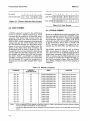
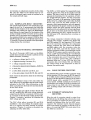
·nTABLE
1-1.
2-1.
2-2.
2-3.
2-4.
2-5.
2-6.
3-1.
3-2.
,
TABLES
TITLE
PAGE
Specifications ..........................
DC Interface Characteristics ...........
User-Configured Jumpers ..............
Gain Resistor Values ...................
iSBXTM BUS Pin Assignment ..........
Connector Jl Pin Assignment ..........
Compatible Jl Connector Details .......
I/O Port Addresses ....................
WRITE Commands ....................
1-2
2-2
2-4
2-5
2-5
2-7
2-7
3-1
3-2
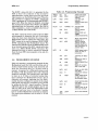
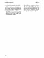
TABLE
3-3.
5-1.
5-2.
5-3.
5-4.
5-5.
TITLE
PAGE
Programming Example .................
Power Supply Voltage Requirements ...
ADC Offset and Range Adjustment
Test Input ..... . . . . . . . . . . . . . . . . . . . . ..
Voltage Source Input Required
for ADC Offset and
Range Adjustment ...................
Replaceable Parts ......................
Manufacturer Codes ....................
3-3
5-2
5-2
5-2
5-3
5-4
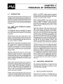
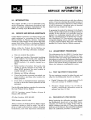
ILLUSTRATIONS
FIGURE
1-1.
2-1.
2-2.
2-3.
2-4.
2-5.
2-6.
TITLE
PAGE
iSBX 31FM Analog Input
Multimodule™ Board .................
Board Dimensions (Inches) .............
Mounting Clearances ...................
Voltage Gain Resistor Location ........
Single Ended Input Configuration .. . ..
Differential Input Configuration .......
Mounting Technique ...................
1-1
2-2
2-3
2-4
2-8
2-8
2-9
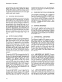
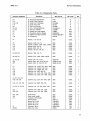
FIGURE
3-1.
3-2.
4-l.
5-l.
5-2.
TITLE
PAGE
Channel Selection Byte Format ........
Data Format ...........................
iSBX 311 ™ Board Functional Block
Diagram .............................
iSBX 31FM Analog Input Multimodule™
Board Parts Location Diagram .......
iSBX 311 ™ Analog Input Multimodule™
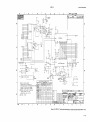
Board Schematic Diagram ...........
3-2
3-2
4-3
5-5
5·7
v