1
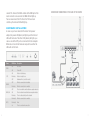
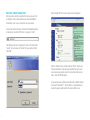
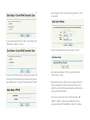
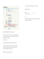
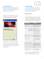
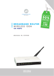
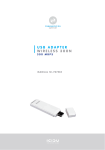
BROADBAND ROUTER
WIRELESS 150N
150 MBPS
MANUAL NI-707517
ENGLISH
C O N T E N T S O F T H E PA C K A G E
5
T E C H N I C A L S P E C I F I C AT I O N S
5
R A N G E O F A P P L I C AT I O N S
5
H A R D W A R E I N S TA L L AT I O N
6
R O U T E R C O N F I G U R AT I O N
8
WPS
14
CE/FCC
15
WA R R A N T Y
18
3
ENGLISH
BROADBAND ROUTER
WIRELESS 150N
150 MBPS
Thank you for buying this 150N router. If you want to
interconnect several PC’s for shared Internet access,
you will need an additional component to connect
the PCs. This router allows you to set up a wireless
network, quickly and efficiently.
C O N T E N T S O F T H E PA C K A G E
Before starting the installation first check that all necessary
parts are present. The box should contain:
-
Wireless Router 150N
Power adapter 9V~ 850mA
CD with full manual
User manual
T E C H N I C A L S P E C I F I C AT I O N S
802.11n wireless protocol
Supports: IEEE 803.3, IEEE 803.3u, IEEE 802.11b,
and IEEE 802.11g
Supports: WEP/WPA/WPA2/802.1X data encryption
Supports: 64/128/152 bit WEP encryption security
Maximum wireless data transfer speed: 150Mbps
Aerial 3dBi
Web Based Management
Supports: Dynamic IP, Static IP, PPPoE
1 x WAN, 4 x LAN RJ-45 UTP ports
Built-in NAT and DHCP server
Supports: VPN pass through
Independent of operating system
R A N G E O F A P P L I C AT I O N S
This router allows you to set up a wireless broadband Internet connection on multiple computers. On top of a shared
Internet connection, you can also set up a network between
4
5
several PCs. Connect the ADSL modem to the WAN port of the
router and after a few seconds the WAN LED will light up.
You can now connect the PCs. Once the PCs have been
started up, the relevant LED will light up.
OVERVIEW OF CONNECTIONS AT THE BACK OF THE ROUTER
H A R D W A R E I N S TA L L AT I O N
As soon as you have connected the router to the power
adapter, the power LED (Green) will light up and the link/act
LEDs will flash once. The other LEDs (Green) will light up as
soon as one of the UTP ports are connected to the computer.
When data is transferred from one computer to another the
LEDs will start to flash.
LED INDICATORS
Name
PWR
SYS
WLAN
WAN, 1-4
WPS
6
LED Action
Description
OFF
No Power
ON
Power ON
ON
Router is starting up
Flashing
Router is ready to use
OFF
Hardware Error (reset the router)
OFF
Wireless connection is disabled
Flashing
Wireless connection is enabled
OFF
There is no network connection between computer and router
ON
There is a network connection between computer and router
Flashing
There is data activity on the network
Flashing1
Wireless connection is enabled
Flashing2
Error
On
There is a network connection
7
R O U T E R C O N F I G U R AT I O N
After you have correctly connected the router, you can start
to configure it. For some providers you will need addition
information, such as your username and a password.
After clicking “OK” the router setup screen is displayed.
Start up the Internet browser and enter the following address
in the address bar http://192.168.1.1 and press “Enter”
The following screen is displayed. To access the router enter
“admin” for username and “admin” for password and then
click “OK”
Click on “Quick Setup” and then click on “Next”. Select your
Internet connection, and after your provider has given you a
username and password, which is needed for cable connections, select the PPPoE option.
If you already have an ADSL connection with an ADSL modem
then select ‘Dynamic IP”. The IP address is automatically allocated by your provider which the router will then use.
8
9
After clicking on “Next” the “Quick Setup - Wireless” screen
is displayed.
If you have Dynamic IP click on “Next” to go directly to the
“Quick Setup – Wireless” screen
If there is nothing you want to change, click on “Next”.
If you have a PPPoE connection, enter your username in the
“Account name” field and the password you were given by
your provider in the “Password” field. Then click on “Next”.
After you have clicked on “Finish” you will return to the
“Router status” screen.
Now that the router has been set up it is important that the
wireless function of the router is protected. If you do not
protect the router then the people around you will be able to
use your Internet connection.
In the main screen of the router, click the “Wireless” Ä
“Wireless Settings” option and the following screen is
displayed. Enable the “Enable Wireless Security” function.
10
11
Use this space to write down your router’s settings.
Wireless Settings
SSID
: ……………………………..
PSK Passphrase: ……………………………..
NB
To get the most out of your router, please see the complete
manual on the CD-ROM.
Select WPA-PSK/WPA2-PSK for security type.
For the “PSK Passphrase” function enter your own network
key and make a note of the key as you will need it to make a
wireless client connection
with the router.
After you have entered all the details, click on “Save”.
The following message appears: “Selecting the incorrect
country may cause interference with other devices and
violate the applicable law” Click “OK”.
Click ‘OK’ again to restart the router.
12
13
W P S C O N F I G U R AT I O N
WPS (Wi-Fi Protected Setup) function allows you to add a new
wireless device to an existing network quickly. WPS can only
be used if the router also supports this feature.
C E M A R K WA R N I N G
This is a class B product. In a domestic environment, this
product may cause radio interference, in which case the user
may be required to take adequate measures.
NATIONAL RESTRICTIONS
Push the button on the router and on the adapter and wait
until the following screen appears. Then click “Finish”.
The WPS connection can also be established by making the
connection in the software utility. This will also enable you to
use a PIN code. For more information on WPS, please read the
full manual on the CD.
This device is intended for home and office use in all EU countries (and other countries following the EU directive 1999/5/EC)
without any limitation except for the countries mentioned below:
COUNTRY RESTRICTION
REASON/REMARK
Bulgaria
None
General authorization required for
outdoor use and public service
France
Outdoor use limited to Military Radiolocation use.
10 mW e.i.r.p. within the Refarming of the 2.4 GHz band has
band 2454-2483.5 MHz been ongoing in recent years to
allow current relaxed regulation.
Full implementation planned 2012
Italy
None
If used outside of own premises,
general authorization is required
Luxembourg
None
General authorization required for
network and service supply(not for
spectrum)
Norway
Implemented
This subsection does not apply for
the geographical area within a
radius of 20 km from the centre of
Ny-Ålesund
Russian Federation
None
Only for indoor applications
Please don’t use the product outdoors in France S’il vous
plaît ne pas utiliser le produit à l’extérieur en France.
14
15
F C C S TAT E M E N T
This equipment has been tested and found to comply with the
limits for a Class B digital device, pursuant to part 15 of the
FCC Rules. These limits are designed to provide reasonable
protection against harmful interference in a residential installation. This equipment generates, uses and can radiate radio
frequency energy and, if not installed and used in accordance
with the instructions, may cause harmful interference to radio
communications. However, there is no guarantee that interference will not occur in a particular installation. If this equipment does cause harmful interference to radio or television
reception, which can be determined by turning the equipment
off and on, the user is encouraged to try to correct the interference by one or more of the following measures:
-
-
Any changes or modifications not expressly approved by the
party responsible for compliance could void the user’s authority to operate the equipment.
F C C R F R A D I AT I O N E X P O S U R E
S TAT E M E N T:
This device has been tested for compliance with FCC RF
Exposure (SAR) limits in the typical laptop computer
configuration and this device can be used in desktop or
laptop computers. This device cannot be used with handheld
PDAs (personal digital assistants). This device and its
antenna must not be co-located or operated in conjunction
with any other antenna or transmitter. SAR measurements
are based on a 5mm spacing from the body and that
compliance is achieved at that distance.
Reorient or relocate the receiving antenna.
Increase the separation between the equipment
and receiver.
Connect the equipment into an outlet on a circuit
different from that
to which the receiver is connected.
Consult the dealer or an experienced radio/ TV
technician for help.
This device complies with part 15 of the FCC Rules. Operation
is subject to the following two conditions:
1)
2)
16
This device may not cause harmful interference.
This device must accept any interference received,
including interference that may cause undesired
operation.
17
WA R R A N T Y
Unless specified otherwise, all items sold under the ICIDU
name are covered by a two-year warranty. No warranty or
support is provided for the software and rechargeable
batteries that are provided. Claims under warranty can
be made only via the dealer from whom the item was
purchased.
Specifications can be changed without notice.
All ICIDU products comply with current European safety and
environmental standards and legislation. For further details,
visit our website www.icidu.com
ICIDU is a registered trademark. All other brand names and rights in
connection with them are and remain the property of the rightful owner.
© Copyright 2009 ICIDU
All rights expressly reserved
18