1
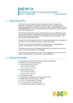
USER MANUAL
27999-01A
18 MONTH “BRONZE MEDAL” WARRANTY
SUN-CO, Inc., through a manufacturer’s warranty, warrants your tanning unit to be free of structural
defects in material and workmanship, under normal use, for its lifetime. SUN-CO, Inc. will, at its discretion, repair any structural defect which materially affects the performance of the tanning unit, or
replace the tanning unit.
For eighteen (18) months following the purchase date of your tanning unit, SUN-CO, Inc. will provide
replacements for parts that prove to be defective in material or workmanship, with the following exceptions: gas springs are warranted against manufacturer’s defects for a period of one (1) year; ballasts are
warranted against manufacturer’s defects for a period of six (6) months; fluorescent lamps, lamp
starters and cracked or broken endcaps are warranted against manufacturer’s defects for a period of
ninety (90) days; blue and clear filter glass (for face tanners) are warranted against manufacturer’s
defects for a period of thirty (30) days; acrylics are warranted against manufacturer’s defects for a period of ninety (90) days following the purchase date of your tanning unit.
SUN-CO, Inc. also extends to you a two (2) year parts warranty on all T-Max® remote system components. External voltage transformers (buck-boosters) are covered by a one (1) year parts and labor
warranty, provided you send back the defective transformer.
Labor costs associated with repair or replacement work covered by this warranty will be reimbursed
for repair or replacement work required to be performed for a period of thirty (30) days following the
purchase date of your tanning unit. Normal wear and tear, damage from misuse or abuse, damage
incurred in transit or damages resulting from unauthorized repairs or modifications are not covered
by this warranty. Warranty coverage does not include cosmetic abnormalities such as scratches, nicks,
dents, or other cosmetic changes that do not materially interfere with the function of the tanning unit.
THIS 18 MONTH “BRONZE MEDAL” WARRANTY IS EXPRESSLY MADE IN LIEU OF ANY
OTHER WARRANTIES, EXPRESS OR IMPLIED, INCLUDING ANY IMPLIED WARRANTIES OF
MERCHANTABILITY AND FITNESS FOR A PARTICULAR PURPOSE, WHICH ARE HEREBY DISCLAIMED. No one has the authority to change or modify this 18 Month “Bronze Medal” Warranty in
any respect. To obtain service under this 18 Month “Bronze Medal” Warranty, contact SUN-CO, Inc. at
1-800-382-8932. Proof of purchase, including serial number, is required.
IN NO EVENT SHALL YOUR DISTRIBUTOR OR THE MANUFACTURER BE LIABLE AT LAW OR
IN EQUITY FOR ANY LOSS, LIABILITY, DAMAGE OR EXPENSE IN AN AMOUNT IN EXCESS OF
THE PURCHASE PRICE RECEIVED, OR FOR LOSS OF USE OR PROFITS, LOSS OF TIME, INCONVENIENCE, RENTAL OR SUBSTITUTE PRODUCTS, LOSS OF BUSINESS, LOSS OF INCOME, OR
ANY OTHER INCIDENTAL, INDIRECT, SPECIAL OR CONSEQUENTIAL DAMAGES. Some states
do not allow the exclusion or limitation of incidental or consequential damages, and the above limitation or exclusion will not apply to residents of some states. This 18 Month “Bronze Medal” Warranty
gives you specific, legal rights and you may have other rights which may vary from state to state.
All warranty service must be performed by an authorized service person using only ETS authorized
replacement parts. Use of non-authorized parts may void your warranty. All labor charges must be
authorized by SUN-CO, Inc. prior to the start of repairs and must not exceed the established rates and
time allotment policies established by SUN-CO, Inc. If your tanning unit must be returned for service,
all freight charges shall be at your expense. Contact SUN-CO, Inc. at 1-800-382-8932 for the authorized
Service Center nearest you. This warranty is serial number specific and only applies to tanning units purchased through SUN-CO, Inc. This warranty is extended to the individual or legal entity whose name
appears on the original sales document and may not be transferred to any other individual or legal entity. This warranty is void if the tanning unit is modified in any manner from its original design.
Record this information for ease of service:
Date of purchase:
Bench serial number:
Canopy serial number:
27999-01A
To obtain warranty service contact your place of purchase. Proof of purchase, including serial number, is
required for verification.
1
Welcome
Congratulations on your purchase of this technologically advanced sun tanning unit. It has been
designed to provide years of dependable service.
Please read all the instructions in this booklet before installing and using the unit. Always be sure to
observe all safety precautions.
Contents
Safety Information . . . . . . . . . . . . . . . . . . . . . . . . . . . . . . . . . . . . . . . .2
Installation . . . . . . . . . . . . . . . . . . . . . . . . . . . . . . . . . . . . . . . . . . . . . .3
Unpacking and Inspection . . . . . . . . . . . . . . . . . . . . . . . . . . . . . .3
Tools Required . . . . . . . . . . . . . . . . . . . . . . . . . . . . . . . . . . . . . .3
Pre-Installation Planning . . . . . . . . . . . . . . . . . . . . . . . . . . . . . . .4
Hardware Inventory . . . . . . . . . . . . . . . . . . . . . . . . . . . . . . . . . . .5
Assembly Procedures . . . . . . . . . . . . . . . . . . . . . . . . . . . . . . . . . .6
Electrical Connections . . . . . . . . . . . . . . . . . . . . . . . . . . . . . . . .13
Remote Connections . . . . . . . . . . . . . . . . . . . . . . . . . . . . . . . . .14
27999-01A
Operation . . . . . . . . . .
Before You Tan . . .
Exposure Times . .
Using Your Sunbed
....
....
....
...
.
.
.
.
.
.
.
.
.
.
.
.
.
.
.
.
.
.
.
.
.
.
.
.
.
.
.
.
.
.
.
.
.
.
.
.
.
.
.
.
.
.
.
.
.
.
.
.
.
.
.
.
.
.
.
.
.
.
.
.
.
.
.
.
.
.
.
.
.
.
.
.
.
.
.
.
.
.
.
.
.
.
.
.
.
.
.
.
.
.
.
.
.
.
.
.
.
.
.
.
.
.
.
.
.
.
.
.
.
.
.
.
.
.
.
.
.
.
.
.
.18
.18
.18
.19
Care and Maintenance . . . . . . . .
Cleaning After Use . . . . . . .
Thorough Periodic Cleaning
Mechanical Inspection . . . .
Replacing Lamps . . . . . . . .
.
.
.
.
.
.
.
.
.
.
.
.
.
.
.
.
.
.
.
.
.
.
.
.
.
.
.
.
.
.
.
.
.
.
.
.
.
.
.
.
.
.
.
.
.
.
.
.
.
.
.
.
.
.
.
.
.
.
.
.
.
.
.
.
.
.
.
.
.
.
.
.
.
.
.
.
.
.
.
.
.
.
.
.
.
.
.
.
.
.
.
.
.
.
.
.
.
.
.
.
.
.
.
.
.
.
.
.
.
.
.
.
.
.
.
.
.
.
.
.
.
.
.
.
.
.
.
.
.
.
.
.
.
.
.
.21
.21
.21
.21
.22
Troubleshooting . . . . . . . . . . . . . . . . . . . . . . . . . . . . . . . . . . . . . . . . .24
2
Safety Information
LABELING NOTICE: Labels are affixed on all systems to inform the user of possible dangers. Regulations are stated in 21 CFR, Section
1040.20, and require that all products manufactured after September 8, 1986 which use sunlamps must display the following:
Ultraviolet radiation. Follow instructions. Avoid overexposure. As with natural sunlight, overexposure can cause
eye and skin injury and allergic reactions. Repeated exposure may cause premature aging of the skin and skin
cancer. WEAR PROTECTIVE EYEWEAR; FAILURE TO MAY RESULT IN SEVERE BURNS OR LONGTERM INJURY TO THE EYES.
Medications or cosmetics may increase your sensitivity to the ultraviolet radiation. Consult physician before using sunlamp if you are
using medications or have a history of skin problems or believe yourself especially sensitive to sunlight. If you do not tan in the sun, you
are unlikely to tan from the use of this product. Children, the elderly, or fair skinned people who always burn easily and either never tan
or tan minimally should not use this equipment.
DANGER
To use, lie down under canopy and pull down as far as adjustment will allow. Do not use without clear plastic panels in place. Untanned
persons should not tan on consecutive days during their first week of tanning. Never tan more than once a day. Tanning normally appears
after the first few sessions and maximizes after approximately four weeks. Tan once or twice per week thereafter to maintain appearance.
Persons already having a base tan may begin at advanced levels corresponding to the extent of their base tan.
RECOMMENDED EXPOSURE TIMES IN MINUTES
Skin Type:
I Sensitive Skin
II Light
III Normal
IV Dark
MAXIMUM EXPOSURE TIME IS 14 MINUTES
Level 1/Week 1
1st-3rd Sessions
(Burns easily and severely and does not tan.)
(Burns easily and severely and tans minimally.)
(Burns moderately and tans average.)
(Burns minimally, tans easily and above average.)
2
3
4
Level 2
Level 3
Level 4
NOT RECOMMENDED FOR TANNING
5
8
11
6
10
14
8
11
14
Subsequent
Maximum
14
14
14
New lamps emit approximately 10% more ultraviolet radiation during the first 50 hours of operation. Recommended tanning times should
therefore be reduced by approximately 10% during that period.
WARNING: • Read the instructions booklet before using this sunlamp product. • All persons in the room should wear protective eyewear
when lamps are on. Recommended eyewear: provided eyeshields or equivalent eyewear as defined under 21 CFR 1040.20. Other types
of eyewear may not provide adequate protection. Failure to use protective eyewear may result in severe burns or other eye injury. If discomfort develops, discontinue use and consult a physician.
ONLY THE FOLLOWING LAMPS HAVE BEEN CERTIFIED FOR USE IN THE 30 XS-Power:
X-Power Wolff® Model XP71-T12-100W BI PIN
XS-Power Wolff® Model XSP71-T12-100W BI-PIN
XS-Power Dual Twister™ Voltarc® Model XSPDT71-T12-100W BI PIN
DISCONNECT POWER BEFORE ATTEMPTING TO CLEAN, RELAMP, OR ENGAGE IN THE MAINTENANCE OF THIS PRODUCT.
This product is in conformity with performance standards for sun lamp products under 21 CFR PART 1040.20 and
ANSI/UL Standard 482.
88465
27999-01A
THIS EQUIPMENT MUST BE EARTH GROUNDED.
3
installation
Unpacking and Inspection
Inspect these items, including the canopy
and bench, and make sure they are free
Your sunbed comes in two cardboard car- from any visible damage. Report the
tons, one for the bench and one for the extent of any damage to the transportation
canopy. Open the cartons and remove the company.
bench and canopy as follows.
Record the serial numbers of the canopy
The bench and canopy are each wrapped and bench in the area provided at the
in plastic. Pull back the plastic and, with back of this manual. This information will
a helper, grasp the bench and pull it from be required whenever you call customer
the carton bottom, leaving the plastic service.
wrap and the carton packaging. Do the
Tools Required
same for the canopy. Do not attempt to
lift either unit with the plastic still on as You will need the following tools to
assemble your sunbed.
it may slip.
27999-01A
Note! The cartons are reusable. You may
wish to save them for future use.
Utility Knife
As you unpack your boxes you should
find the following:
• Canopy unit
• Bench unit
#2 Phillips
• Pair of gas springs
Screwdriver
• Front skirt panel
• Bag containing necessary assembly
hardware, safety goggles, opening
handle and pillow
7/16” Wrench
• Gas spring cover panel
4
Installation - pre-installation planning
Pre-Installation Planning
Before you begin to assemble your sunbed, you should observe the following considerations.
WARNING
Shock hazard.
Disconnect power before
servicing.
• The 30 XS-Power requires a dedicated
circuit capable of providing 30 Amp
service at 220VAC. This unit must be
hardwired directly to a junction box.
We recommend connection by a professional electrician.
• IMPORTANT! Voltage must be below
230V AC or may require a Buck
Booster.
CAUTION
Use of a voltage source above 230V
AC may prevent proper operation of
the sunbed and could cause damage
and void the warranty.
CAUTION
Air from the room is used to cool
the sunbed. Maximum ambient
room temperature should be 80°F.
Place your sunbed no closer than
6” from any wall. Make sure nothing
obstructs the airflow into the
sunbed’s endcaps or out of the fan
openings. A poorly ventilated room
may cause the unit to become hot
and cause discomfort to the user.
CAUTION
Proper assembly of your sunbed
requires three people. Plan to have
a couple of helpers assist you.
27999-01A
Installation - hardware inventory
5
Hardware Inventory
Use the utility knife to cut open the hardware bag. Remove the hardware. Make
sure you have the following items.
Clevis Pin
3/8” x 2 1/64”
Quantity 2
Bridge Pin
Quantity 4
Nylon Floating
Bearing
Quantity 4
Clevis Pin
5/16” x 2 1/32”
Quantity 2
Retaining Ring
Quantity 2
10mm Clevis Pin
Quantity 2
Clevis Fork,
M10 Long
Quantity 4
Bronze Bushing
Quantity 2
Centering Spring
Quantity 4
#10 x 1/2” Screw,
Blue Head
Quantity 8
27999-01A
1/4-20 x 1/2”
Machine Screw
Quantity 8
1/4-20 Locknut
Quantity 8
#10 x 1” Screw,
Quantity 3
Safety Goggles
Quantity 1
6
Installation - assembly procedures
Assembly Procedures
Lower Clevis Fork Assembly
1. Insert the larger clevis pin (3/8” x 2
1/64”) through the hole directly below
the large hole in one of the stand
uprights, as shown.
STAND UPRIGHT
2. Slide a centering spring, a clevis fork
and then another centering
spring onto the clevis pin
and insert the pin the
rest of the way
through the upright.
3. Secure the clevis
pin by inserting
the straight portion
of a bridge pin
through the small
hole in the end of
the clevis pin.
4. Repeat for the other
stand upright. Make sure
the clevis forks point upwards
as shown.
BRIDGE PIN
CLEVIS PIN
CLEVIS FORK
CENTERING SPRING
27999-01A
Installation - Assembly Procedures
Stand Upright Assembly
1. Place the bench approximately where
it will remain, leaving room to work
behind it.
2. Make sure the clevis forks are pointed
up and secure each stand upright to
the rear of the bench pedestals using
four 1/4-20 x 1/2” machine screws
and four locknuts.
LOCKNUT
(others hidden)
27999-01A
STAND UPRIGHT
MACHINE SCREWS
7
8
Installation - Assembly Procedures
Canopy Installation
1. Place two nylon floating bearings into
each canopy arm.
2. Holding the canopy over the bench,
with the canopy arms inside the stand
uprights, insert clevis pins (5/16” x 2
1/32”) through the uprights and nylon
floating bearings to attach the canopy.
3. Secure the clevis pins by inserting the
straight portion of a bridge pin through
the small hole in the end of the clevis
pin.
27999-01A
Installation - Assembly Procedures
9
27999-01A
Install Gas Springs
3. Screw the upper clevis forks onto the
gas springs.
1. Have a helper hold the canopy in its
fully open position.
Do not lower the canopy yet!
2. Make sure the threaded holes in the
lower clevis forks face up (the large
holes above the clevis forks allow finger access). Slide the gas springs down
into the stand uprights, piston end up
as shown, and twist the gas springs
into the lower clevis forks until they
are snug.
10
Installation - Assembly Procedures
Attach Gas Springs
1. With the canopy still raised, slip the
bronze bushings into the hole in the
clevis brackets on the underside of the
canopy arms.
2. Line up both clevis forks and carefully
lower the canopy to engage the clevis
forks. Pay special attention when lowering the canopy that the clevis forks
do not damage the bronze bushings.
Bronze is excellent for smooth pivoting applications such as this, but
tends to be soft compared to the
steel clevis fork.
Clevis Bracket
3. Lock the clevis forks in place
with the 10mm clevis pins.
4. Secure the clevis pins with the
retaining rings.
NOTE: When this assembly is complete,
lift and lower the canopy a few times to
lubricate the gas springs for optimum performance.
27999-01A
Installation - Assembly Procedures
27999-01A
Attach Cover Panels
1. Put the gas spring cover panel in place
and secure with two blue-headed #10
x 1/2” screws in each end. The skirt
installs in the same way.
11
12
Installation - Assembly Procedures
Attaching Handle to Canopy
1. Install the handle by inserting the three
#10 x 1” Phillips head screws through
the handle and into the predrilled
holes on the canopy.
27999-01A
Installation - electrical connections
13
Electrical Connections
NOTE: Your sunbed is designed to accept
an input from a remote control device.
At the rear of the bed, insert canopy plug The remote control is optional. If you
(A) into bench socket (B). Connect power plan on using a remote system refer to
cord (C) as described in Pre-Installation Remote Connections.
Planning. Again, a professional electrician
is recommended. The Remote Control ATTENTION: Although the Remote
Bypass plug is already installed in one of Control Bypass plug provided with your
the remote control ports as shown. Your sunbed will work wherever a T-Max® tersunbed will not operate without the minator is called for in the series, the TRemote Control Bypass plug or a remote Max® terminator will not work as a
system connected. Your equipment is now bypass plug. A bypass plug is needed only
when your sunbed is operated without a
ready for use.
remote system connected.
Remote Control
Ports
27999-01A
Remote Control
Bypass plug
14
Installation - remote connections
Remote Connections
Your sunbed incorporates advanced circuitry
allowing it to connect and communicate with
most remote control systems. If a remote system is
to be used, first determine whether the remote system is a T-Max® System or a standard remote system operating with a control relay. Follow the
appropriate instructions for your system type.
REMOTE PORTS
WIRED
REMOTE
PORTS (RJ-22)
WIRELESS
REMOTE
PORT (RJ-11)
Three remote ports, located near the canopy
power cord allow connection to a remote system,
two RJ-22 (4-wire) ports and one RJ-11 (6-wire)
port. Both RJ-22 remote ports are identical,
allowing connection of multiple units in a “daisy
chain” configuration. The RJ-11 port is intended
for the T-Max® wireless remote system. A Remote
Control Bypass plug is already installed in one of
the RJ-22 remote ports to bypass the remote functionality, otherwise known as “stand-alone” operation. Your sunbed will not operate without the
Remote Control Bypass plug or a remote system
connected.
CAUTION
The T-Max® remote systems offer the ultimate
in sunbed control, while allowing the tanner
easy straightforward operation. Your sunbed is
configured to directly connect to this system,
including the new wireless remote system.
The circuitry inside your sunbed eliminates
the need for the T-Max® 1A or 3A when connecting to the T-Max® Manager series. Your
sunbed supports the auto addressing feature
of the latest T-Max® Manager models and the
following parameters: 5, 6, 7, 8, 9, 10, 15 and
23. See your T-Max® manual for descriptions
of these parameters and how they function.
T-Max® Wireless Remote System
The T-Max® AP-900 eliminates wires in your
salon, allowing easy setup without hiring an
electrician to run wires. It also protects your
investment from damage by isolating each
unit from one another. Your sunbed arrives
“wireless ready”, which means it connects
directly to the T-Max® wireless system. Older
tanning beds, and T-Max® managers, also utilize this system but require a T-Max “Power
Injector” (PI) to provide the needed power to
the wireless unit.
Remote System Hook-up Scenarios
Follow the diagrams on the next few pages to
see the many different scenarios for hooking
up your salon. If you need further assistance,
call T-Max® directly at (417) 338-5101.
27999-01A
The remote connection is not designed to supply
or accept high voltage, nor can it provide power
to an external timer. The sunbed’s remote interface circuitry operates on 5 volts, attempting to
connect it to any higher voltages will damage the
sunbed as well as void your warranty.
T-Max® Products
Installation - remote connections
Scenario 1 - T-Max® Manager Series with
Complete Wireless
Connect one AP-900 (with Power
Injector) to the Manager and one
AP-900 to each of the tanning
beds. Install as many beds as you like with
this configuration. Units that do not communicate with T-Max will need an AP-900 with
Power Injector and an additional 3A to operate.
You can place your sunbed at any location in the
series.
Scenario 2 - T-Max 3A with Wireless
Connect one AP-900 (with Power Injector) to the TMax® 3A and one AP-900 to the tanning bed in
single bed installations.
27999-01A
Scenario 3 - T-Max® Manager Series with
Wireless combo
Wireless can be easily added to an existing
salon already utilizing T-Max®. Connect one
AP-900 (with Power Injector) to the Manager
and one AP-900 to each wireless ready tanning bed. The rest of the salon may be
“daisy-chained” together and connected to
the Manager.
15
16
Installation - remote connections
Scenario 4 - T-Max® Manager
Series with Wireless combo 2
Connect one AP-900 (with Power
Injector) to the Manager and one
AP-900 to a wireless ready tanning bed.
The rest of the salon may be “daisychained” together and connected to the
wireless equipped tanning bed, eliminating
the need to wire the Manager to the tanning
beds.
Scenario 5 - T-Max® Manager Series with wires
As always, this tanning bed is fully compatible with a wired T-Max® system.
Simply connect the RJ-22 modular
cable(s), described in the T-Max®
Manager manual, into the remote port(s) located
on the canopy and follow the instructions that
came with your remote system.
Scenario 6 - Single Bed wired to T-Max® 3A
In single sunbed installations, the T-Max® 1A and
3A can offer the same control as the T-Max®
Manager, eliminating the need for a Manager. If
you’re using a 1A in this manner, it must have a
chip labelled “master” installed on its circuit
board. The remote control bypass plug must not be
used in this configuration. The 3A may be used as
a “master” with no modification.
After you have set the T-Max® 1A’s, or 3A’s, address
to “0” (refer to your T-Max® user’s guide) and the
sunbed’s address to “1”, simply connect the RJ-22
modular cables, described in the T-Max® user’s
guide, directly into either of the smaller ports located near the canopy power cord and either port on
the back of the T-Max® 1A or 3A.
27999-01A
NOTE: A T-Max® 1A with a
“master” chip can be substituted
for a 3A.
Installation - remote connections
Scenario 7 - Non T-Max® Remote System wired
to unit
Most non-T-Max® remote systems control the
sunbed by the use of a relay. The relay operates
the sunbed by connecting and disconnecting a
pair of wires leading from the sunbed. Refer to the
user’s manual provided with your remote system
to determine if it operates in this way. To connect
your sunbed to this type of system a remote interface kit is required. Contact your place of purchase
to obtain the kit. The illustration below details a
typical connection. Follow the instructions provided with the kit and from the remote’s manual to
make the necessary connections.
17
Setting the sunbed address manually
Before connecting your sunbed to the T-Max®
Manager or T-Max® 1A or 3A, the address of
your sunbed must first be set. Set the “id” manually as described below.
Setting the “id”
1. Make sure no cables are plugged into
your sunbed’s remote ports.
2. Remove and reapply power to the unit.
3. Press and hold the stop button, located
on the sunbed display, for three seconds
and release. The display should indicate
an “id” number from “oF” to “252”.
1-99
100-199
200-252
CAUTION
27999-01A
The remote connection is not designed to supply
or accept high voltage, nor can it provide power
to an external timer. The sunbed’s remote interface circuitry operates on 5 volts, attempting to
connect it to any higher voltages will damage the
sunbed as well as void your warranty.
4. If you are using a T-Max® 1A or 3A as a
“master” remote, the “id” of the sunbed
must be set to “1”. If you are using a TMax® Manager each sunbed must be
assigned a different “id”. To set the “id”
press the timer button, to count up, or
the body fan control button, to count
down, until the desired number is
achieved.
5. Press the stop button to return to the
normal display mode.
18
operation
Before You Tan
DANGER
Some medication may increase your sensitivity to ultraviolet light. It is recommended
that you consult a physician before using
this sunbed if taking any medication or if you
suspect that your skin might be especially
sensitive to sunlight.
Before using your sunbed, please note the
following important precautions.
• Your skin should be free of cosmetics,
tanning oils, or other body lotions
prior to tanning except for those
specifically made for use with tanning
devices. However, do not remove natural body oils by bathing or showering
immediately before tanning.
DANGER
Shock hazard.
Do not operate this device near
water or while you are wet.
Exposure Times
• Your hair should be free of gels,
mousses, sprays, or other hair products
prior to tanning. These products can
cause damage to the sunbed acrylic.
As an alternative, a shower cap or
towel can be worn to keep treated hair
away from the sunbed surfaces.
Follow the guidelines for skin type and
exposure times as shown in the table
below. Untanned persons should not tan
on consecutive days during their first week
of tanning. Never tan more than once a
day. Tanning normally appears after the first
few sessions and maximizes after approximately four weeks. Tan once or twice per
• This unit intended for individual use. week thereafter to maintain appearance.
Only one pair of eyewear is included. Persons already having a base tan may
begin at advanced levels corresponding to
the extent of their base tan.
RECOMMENDED EXPOSURE TIMES IN MINUTES
(Burns easily and severely and does not tan.)
(Burns easily and severely and tans minimally.)
(Burns moderately and tans average.)
(Burns minimally, tans easily and above average.)
2
3
4
Level 2
Level 3
Level 4
NOT RECOMMENDED FOR TANNING
5
8
11
6
10
14
8
11
14
Subsequent
Maximum
14
14
14
27999-01A
Skin Type:
I Sensitive Skin
II Light
III Normal
IV Dark
MAXIMUM EXPOSURE TIME IS 14 MINUTES
Level 1/Week 1
1st-3rd Sessions
operation - using your sunbed
19
Using Your Sunbed
When connected to the T-Max® Manager or T-Max® 1A or 3A.
A
B
C
D
E
F
G
A Face tanner control - Turns face tanners 1. Lift the canopy, lie down on the bench
on and off during use. Face tanner
lamps require one minute to relight.
(Units equipped with face tanner only)
B Body tanner control - Turns body lamps
(face up), lower the canopy toward your
body using the canopy handle. See Safety
Information for positioning instructions.
2. Put on your safety goggles.
on and off during use. (Units equipped 3. Assuming the remote system has been set
to allow a pre-tanning delay time, the timer
with face tanner only)
display (E) will repeatedly flash the delay
C Body fan control - Controls the speed of
symbol “dL” and then the remaining delay
the body fan during use.
time. Press the timer button (G) or wait
until the delay time has expired to begin
D Body fan speed indicator - Indicates
the tanning session. The lamps will turn on
speed of fan. (OFF - LOW - MED - HI)
and the timer will begin to count down.
E Timer display - Displays remaining time. 4. When the timer reaches 0 the lamps turn
F Stop button - Interrupts tanning session.
off. If you want to stop your session before
time expires, press the stop button (F).
G Timer button - Turns bed on. Timer dis- 5. Raise the canopy by using the outer edge,
play shows remaining time.
27999-01A
WARNING
Wear protective eyewear.
Failure to may result in severe burns or
longterm injury to the eyes.
do not push up on the acrylic shield. The
cooling fans run for a period of time after
the lamps shut off to aid in cooling the
sunbed. The timer will indicate “..” as a
reminder to clean the sunbed. After the
sunbed is cleaned press the timer button
and the display will return to “0”.
20
operation - using your sunbed
Using Your Sunbed
When used as a stand alone unit or when connected to a remote system using a control relay.
A
B
C
D
E
F
G
A Face tanner control - Turns face tanners 1. Lift the canopy, lie down on the bench
on and off during use. Face tanner
lamps require one minute to relight.
(Units equipped with face tanner only)
B Body tanner control - Turns body lamps
(face up), lower the canopy toward your
body using the canopy handle. See Safety
Information for positioning instructions.
2. Put on your safety goggles.
on and off during use. (Units equipped 3. Press the timer button (G) to begin the tanning session. The lamps will turn on and
with face tanner only)
the timer will begin to count down.
C Body fan control - Controls the speed of
4. If a tanning time less than the displayed
the body fan during use.
time is desired repeatedly press the timer
D Body fan speed indicator - Indicates
button (G) to decrease the remaining time.
5. When the timer reaches 0 the lamps turn
off. If you want to stop your session before
E Timer display - Displays remaining time.
time expires, press the stop button (F). You
will have ten seconds to restart with the
F Stop button - Stops tanning session.
remaining time, otherwise the timer will
G Timer button - Turns bed on. Timer disreset to 0.
play shows remaining time. If a lesser 6. Raise the canopy by using the outer edge
time is desired, press timer button until
of the canopy, do not push up on the
desired time is displayed.
acrylic shield. The cooling fans run for a
speed of fan. (OFF - LOW - MED - HI)
WARNING
27999-01A
Wear protective eyewear.
Failure to may result in severe burns or
longterm injury to the eyes.
period of time after the lamps shut off to
aid in cooling the sunbed.
care and maintenance
Cleaning After Use
Clean and disinfect your tanning bed’s
bench and canopy after each use. Use a
non-abrasive disinfectant cleaner that does
not contain ammonia or ammonia derivatives. Ammonia may damage the acrylic
shield. Spray the acrylic lightly with disinfectant and wipe dry with a clean soft cloth.
We recommend Australian Gold® pH
Neutral Disinfectant Cleaner.
Thorough Periodic Cleaning
Introduction
The cooling fans draw air through the bed
and over time will cause a dust buildup on
the lamps and reflectors. This will reduce
the tanning effectiveness of the bed. When
a dust buildup is observed, it is necessary to
thoroughly clean the inside of the bench
and canopy.
WARNING
27999-01A
Shock hazard.
Disconnect power before removing
any protective covers.
Cleaning the Canopy and Bench
Step 1 Remove the acrylic shields and
lamps as described in Lamp and
Acrylic Replacement.
Step 2
Step 3
Step 4
Step 5
21
With a soft cloth, wipe the entire
length of each lamp to remove
any film buildup.
Clean both sides of the acrylic
shields with a non-ammonia disinfectant cleaner.
Wipe the reflectors with a clean
damp cloth.
Re-install the lamps and acrylic
shields.
Mechanical Inspection
Your tanning bed has been built for years of
service. To ensure trouble-free operation
throughout its life, inspect the unit’s
mechanical integrity every 400-500 hours
of use.
• Inspect the unit’s fasteners verifying
that all are firmly in place.
• Inspect gas springs for signs of wear.
Gas springs that will not hold the
canopy in the full open position when
raised should be immediately replaced.
See Troubleshooting.
• Inspect the AC power cord and its
connections.
• Inspect the acrylic. Broken, cracked or
badly scratched acrylics should be
immediately replaced.
22
care and maintenance - replacing lamps
Replacing Lamps
Standing at the front of the unit, lift the
exposed edge of the acrylic slightly and
carefully begin sliding it toward you until
Introduction
it is removed from the sunbed. This might
To be assured of maximum tanning effecbe easier with the help of another person.
tiveness, change lamps after approximately 800-1000 hours of use. Tanning will
After changing the lamps, replace the
continue after this time but at a slower
acrylic shield by carefully aligning it with
rate. To ensure trouble-free operation of
the channels on the ends of the sunbed
your sunbed, replace the lamp starters
and sliding it into place. Close the hinged
whenever the lamps are replaced.
profile by pushing it back into place until
it snaps tight.
WARNING
Shock hazard.
Disconnect power before servicing.
Removing/Replacing Acrylic Shield
The acrylic shield in the bench and
canopy are secured in place by hinged
profiles which run the length of the bed,
both front and back. Simply pry up on the
inside edge of the profile, starting at the
center of the bed, until it releases its latching action (see figure at right). Continue to
pry up the profile across its entire length
until it swings back freely. Repeat for the
other profile. The long edges of the acrylic
shields are now exposed.
CAUTION
Be careful. The edges of the acrylic shield
may be sharp.
27999-01A
care and maintenance - replacing lamps
23
Removing/Replacing Lamps
Recommended Replacement Lamps
After removing the acrylic shield, replace We recommend using the lamps specified
lamps as follows.
below. Use of uncertified lamps is a violation of Federal regulations and will void
Step 1 Grasp the lamp at one end and your warranty. These lamps have an averat the middle and turn the lamp age life of 800-1000 hours of effective
one quarter turn. Gently remove tanning use. Lamps used longer than that
the lamp from its holders.
begin to lose their effectiveness even
though they continue to light.
Step 2 Reinstall the lamp by inserting
the pins located on the ends of
Recommended Replacement Acrylics
the lamp into the slots on top of Acrylics vary greatly over time in their
the lamp holders and turn the ability to effectively transmit UV light.
lamp a quarter turn. It should Acrylics sold by ETS have been life tested
click in place.
to ensure proper transmission throughout
their useful life.
ONLY THE FOLLOWING LAMPS HAVE BEEN CERTIFIED FOR USE IN THIS EQUIPMENT:
27999-01A
X-Power Wolff® Model XP71-T12-100W BI PIN
XS-Power Wolff® Model XSP71-T12-100W BI-PIN
XS-Power Dual Twister™ Voltarc® Model XSPDT71-T12-100W BI PIN
24
troubleshooting
Problem
Sunbed not tanning
Solution
1.
2.
3.
4.
Clean sunbed, see Thorough Periodic Cleaning.
Ensure supply voltage is between 208 and 230V AC.
Replace lamps if lamp hours are greater than 800hrs.
Replace acrylic.
Lamps fail to light and timer dis- 1. Make sure the unit is connected to a power source.
play is blank
2. Check source of AC power. Reset circuit breaker or replace fuse.
One or more lamps fail to light
1. Check that lamp is installed correctly.
2. Switch unlit lamp with a lamp that lights, if new lamp lights
and old lamp still does not, replace old lamp.
The canopy will not stay up
NOTE: Gas springs are manufactured to hold the canopy in its
fully open position as well as allow it to rest fully closed. If left
open for an extended period of time some creep down may
occur. This is considered normal. Keep the unit closed when
not in use. If the canopy will not stay fully open when raised...
1. Raise and lower the canopy a few times to lubricate gas spring
internal seals.
2. Replace gas springs.
The last minute of tanning time
does not count down from 59 seconds, but some time less than 59
seconds
If the timer button has been pressed to decrease tanning time
during the session, the time expired in the current minute is
subtracted from the last minute.
I forgot what address, or “id”, I set
my sunbed to
By holding the body fan button for 3 seconds the timer display
will briefly display three numbers; the installed timer software
version, a factory set timer code and then the sunbed’s “id”
number.
27999-01A
troubleshooting
Problem
25
Solution
Timer display is indicating Er 91
Timer software error. Disconnect and reapply power to the unit.
Timer display is indicating Er 92
Current sensor indicating unit is off when it should be on.
Contact servicer.
Timer display is indicating Er 93
Current sensor indicating unit is on when it should be off.
Contact servicer.
Timer display is indicating Er 94
Requested session time exceeds maximum time allowed.
Timer display changes to indicate 1. Bypass plug is not installed, see Electrical Connections.
a tanning time after the timer but- 2. A non-SunStar® bypass has been used. See Electrical
ton is pressed but lamps do not
Connections.
come on
3. If remote is being used, other than T-Max® Manager, the external timer may not be activated.
4. Remote wiring is incorrect, see the instructions provided with
the remote interface kit.
My bed is connected to the TMax® Manager remote system
and when the delay time has
expired the timer display starts
counting down but the bed lights
do not come on
The auto start feature of the remote system is disabled, see the
instructions provided with your remote system.
My bed won’t work with the T- 1. The sunbed must first be set to a unique address, see Remote
Connections.
Max® Manager remote system
2. The bypass or terminator plug may be installed in the series in
an inappropriate location. Plug the bypass plug only into the
bed at the end of the series.
27999-01A
Timer display continues to show a 1. T-Max® Manager remote system has not yet been set.
0 after the timer button is pressed 2. Sunbed address is not set correctly, see Remote Connections.
26
troubleshooting
Problem
My bed is connected to a T-Max®
remote system but I am having
trouble getting into “id” mode
Solution
You have probably attempted to connect your sunbed to the
remote system already. Disconnect the remote plug(s) from the
ports at the back of the sunbed, wait 90 seconds and try again.
My bed, connected to a T-Max®
Manager, did not display “dL” but
does indicate:
“0”
1. Remote device has not been set.
2. The sunbed has not been connected to the remote system, see
Remote Connections.
a tanning time and the lamps 1. Delay time of T-Max® Manager has not been set.
have come on
2. Delay time has expired and session has begun.
a tanning time but the lamps
Auto start function of T-Max® Manager has been turned off.
have not come on
Press the timer button to turn on lamps.
When auto-addressing the first bed
does not register an “id”
When using the auto address feature of the T-Max® Manager
you must wait 10 seconds from the time you start the auto
address function before addressing the first bed.
When using a T-Max® 1A my
sunbed won’t function properly
SunStar® Bypass plugs or terminator plugs may be needed if
the T-Max® 1A and the sunbed are over 100 feet apart. Install
the plugs in the open remote port in the sunbed and the TMax® 1A.
My salon suffers frequent, short
power outages and clients complain about losing session time
If you have a T-Max® Manager, changing parameter 23 from
“0” to “1” will allow the tanning bed to remember how much
time was left when power goes out and resume its session
after power is restored. Consult your T-Max® Manager manual for information on setting parameters.
27999-01A
scheduled maintenance
27
WHEN
What to do
Each use
A. Clean/Disinfect Acrylic Surfaces*
Monthly
400500hrs
8001000hrs
As Needed
✘
B. Clean Lamps*
✘
C. Clean Reflectors*
✘
D. Clean Exterior
✘
E. Check/Clean Fans†
✘
✘
F. Change Lamps and Starters**
✘
G. Change Acrylics**
H. Check Fasteners (nuts, bolts, etc.)*
✘
I. Check Power Cords*
✘
* See Care and Maintenance
** See Lamp and Acrylic Replacement
† Fans are located on the top and bottom of the unit, near the center. Use a vacuum to clean.
What
27999-01A
example
B C D
When
4/15
MAINTENANCE LOG
What
When
What
When
27999-01A
S-30XSPD
Parts List
This is a list of parts which may be replaced by the
consumer. Care should be taken when replacing
anything related to electrical wiring. We recommend contacting a professional electrician. When
calling for parts, first state your bed model as S30XSPD. Then refer to this list and preceding illustration for proper part identification.
Acrylic, Bench
Acrylic, Canopy*
Ballast, 100W
Bushing, Bronze 10mm*
Body Fan Kit* (optional)
Canopy Mounting Arm
Capacitor, 75uF
Contactor
Cover, Bench
Cover, Canopy
Endcap, Kit (with inserts)
Fan
Gas Spring Cover Panel*
Gas Springs*
Handle
Hardware Kit*
Hour Counter*
Keypad Assy Kit
Lamp Holder w/ Starter Holder
Lamp Holder w/o Starter
Lamps*
Manual*
Pillow*
Profile (blank)
Remote Connection PCB
Remote Control Bypass Plug*
Schematic Packet*
Silk-screened Profile (Warnings)
Skirt
Starter, K-12
Timer
Trim Profile (grey)
Wiring Harness, Keypad to Timer
Wiring Harness, Remote PCB to Timer
Record this information for ease of service:
27999-01A
Date of purchase:
Bench serial number:
* Not shown
Canopy serial number:
30 XS-Power
Size
Weight (Pounds)
Minimum Room Size
Electrical Voltage (AC)
Amperage
Circuit Breaker (Amps)
Outlet
Bench Lamps
Canopy Lamps
Ballasts
Cooling System
Timer System
Max. Exposure Time
Back-up Timer
Remote Capability
469
7’ x 9’
220
17
30
Hardwire
XS-Power 100W
XS-Power Dual Twister™ 100W
100W
230cfm “Turbo”(optional)
Digital
14 minutes
Digital “Watchdog” Circuitry
T-Max® compatible
Proudly manufactured in the U.S.A.