1
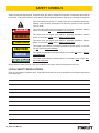
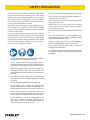
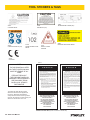
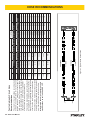
PG10
HYDRAULIC
PROFILE GRINDER
USER MANUAL
Safety, Operation and Maintenance
© 2014 Stanley Black & Decker, Inc.
New Britain, CT 06053
U.S.A.
65846 2/2015 Ver. 6
DECLARATION OF CONFORMITY
DECLARATION OF CONFORMITY
ÜBEREINSTIMMUNGS-ERKLARUNG
DECLARATION DE CONFORMITE CEE
DECLARACION DE CONFORMIDAD
DICHIARAZIONE DI CONFORMITA
Hydraulic Tools
______________________________________________________________________
I, the undersigned:
Ich, der Unterzeichnende:
Je soussigné:
El abajo firmante:
lo sottoscritto:
Weisbeck, Andy
Surname and First names/Familiennname und Vornamen/Nom et prénom/Nombre y apellido/Cognome e nome
hereby declare that the equipment specified hereunder:
bestätige hiermit, daß erklaren Produkt genannten Werk oder Gerät:
déclare que l’équipement visé ci-dessous:
Por la presente declaro que el equipo se especifica a continuación:
Dichiaro che le apparecchiature specificate di seguito:
1.
Category:
Kategorie:
Catégorie:
Categoria:
Categoria:
Grinder, Hydraulic
2.
Make/Marke/Marque/Marca/Marca
Stanley
3.
Type/Typ/Type/Tipo/Tipo:
4.
Serial number of equipment:
Seriennummer des Geräts:
Numéro de série de l’équipement:
Numero de serie del equipo:
Matricola dell´attrezzatura:
PG1011001, PG1011001A
All
Has been manufactured in conformity with
Wurde hergestellt in Übereinstimmung mit
Est fabriqué conformément
Ha sido fabricado de acuerdo con
E’ stata costruita in conformitá con
Directive/Standards
Richtlinie/Standards
Directives/Normes
Directriz/Los Normas
Direttiva/Norme
No.
Nr
Numéro
No
n.
Approved body
Prüfung durch
Organisme agréé
Aprobado
Collaudato
EN
EN ISO
EN
Machinery Directive
11148-7:2011
3744:2010
28927-1:2009
2006/42/EC:2006
Self
Self
Self
Self
5.
Special Provisions:
None
Spezielle Bestimmungen:
Dispositions particulières:
Provisiones especiales:
Disposizioni speciali:
6.
Representative in the Union: Patrick Vervier, Stanley Dubuis 17-19, rue Jules Berthonneau-BP 3406 41034 Blois Cedex, France.
Vertreter in der Union/Représentant dans l’union/Representante en la Union/Rappresentante presso l’Unione
Done at/Ort/Fait à/Dado en/Fatto a Stanley Hydraulic Tools, Milwaukie, Oregon USA
Signature/Unterschrift/Signature/Firma/Firma
Position/Position/Fonction/Cargo/Posizione
2 ► PG10 User Manual
Director of Product Development
Date/Datum/le/Fecha/Data
1-6-11
TABLE OF CONTENTS
DECLARATION OF CONFORMITY...........................................................................................................................2
SAFETY SYMBOLS...................................................................................................................................................4
SAFETY PRECAUTIONS...........................................................................................................................................5
TOOL STICKERS & TAGS.........................................................................................................................................6
HOSE TYPES.............................................................................................................................................................7
HOSE RECOMMENDATIONS...................................................................................................................................8
FIGURE 1. TYPICAL HOSE CONNECTIONS........................................................................................................8
HTMA REQUIREMENTS............................................................................................................................................9
OPERATION.............................................................................................................................................................10
PREVENTATIVE MAINTENANCE...........................................................................................................................12
TOOL PROTECTION & CARE.................................................................................................................................13
TROUBLESHOOTING.............................................................................................................................................14
SPECIFICATIONS....................................................................................................................................................15
ACCESSORIES.......................................................................................................................................................15
PG10 PARTS ILLUSTRATION.................................................................................................................................16
PG10 PARTS LIST...................................................................................................................................................18
SPARK GUARD KIT.................................................................................................................................................20
IMPORTANT
To fill out a Product Warranty Validation form, and for information on your warranty,
visit Stanleyhydraulics.com and select the Company tab, Warranty.
(NOTE: The warranty Validation record must be submitted to validate the warranty).
SERVICING: This manual contains safety, operation, and routine maintenance instructions. Stanley Hydraulic Tools
recommends that servicing of hydraulic tools, other than routine maintenance, must be performed by an authorized
and certified dealer. Please read the following warning.
WARNING
SERIOUS INJURY OR DEATH COULD RESULT FROM THE IMPROPER REPAIR OR SERVICE OF THIS
TOOL.
REPAIRS AND / OR SERVICE TO THIS TOOL MUST ONLY BE DONE BY AN AUTHORIZED AND
CERTIFIED DEALER.
For the nearest authorized and certified dealer, call Stanley Hydraulic Tools at the number listed on the back of this
manual and ask for a Customer Service Representative.
PG10 User Manual ◄ 3
SAFETY SYMBOLS
Safety symbols and signal words, as shown below, are used to emphasize all operator, maintenance and repair actions which, if not strictly followed, could result in a life-threatening situation, bodily injury or damage to equipment.
This is the safety alert symbol. It is used to alert you to potential personal injury
hazards. Obey all safety messages that follow this symbol to avoid possible
injury or death.
DANGER
This safety alert and signal word indicate an imminently hazardous situation
which, if not avoided, will result in death or serious injury.
WARNING
This safety alert and signal word indicate a potentially hazardous situation
which, if not avoided, could result in death or serious injury.
CAUTION
This safety alert and signal word indicate a potentially hazardous situation
which, if not avoided, could result in death or serious injury.
CAUTION
This signal word indicates a potentially hazardous situation which, if not avoided, may result in property damage.
NOTICE
This signal word indicates a situation which, if not avoided, will result in damage
to the equipment.
IMPORTANT
This signal word indicates a situation which, if not avoided, may result in damage to the equipment.
Always observe safety symbols. They are included for your safety and for the protection of the tool.
LOCAL SAFETY REGULATIONS
Enter any local safety regulations here. Keep these instructions in an area accessible to the operator and maintenance personnel.
4 ► PG10 User Manual
SAFETY PRECAUTIONS
Tool operators and maintenance personnel must always
comply with the safety precautions given in this manual
and on the stickers and tags attached to the tool and hose.
•
Do not operate the tool with the wheel guard removed.
•
These safety precautions are given for your safety. Review
them carefully before operating the tool and before performing general maintenance or repairs.
Do not operate a damaged, improperly adjusted, or incompletely assembled grinder.
•
Never wear loose clothing that can get entangled in the
working parts of the tool.
•
Keep all parts of your body away from the rotating
wheel. Long hair or loose clothing can become drawn
into rotating components.
•
Keep the wheel off all surfaces when starting the grinder.
•
Do not use a wheel that is cracked, chipped or otherwise damaged. Always inspect wheels for possible
damage before installation or use.
•
Always use wheels that conform to the specifications
given in the OPERATION section of this manual.
•
Do not reverse grinding wheel rotation direction by
changing fluid flow direction.
•
Do not move the tool until the wheel has stopped rotating. Release the trigger if the power supply has been
interrupted.
Supervising personnel should develop additional precautions relating to the specific work area and local safety
regulations. If so, place the added precautions in the space
provided in this manual.
The model PG10 Hydraulic Profile Grinder will provide safe
and dependable service if operated in accordance with the
instructions given in this manual. Read and understand this
manual and any stickers and tags attached to the grinder
and hose before operation. Failure to do so could result in
personal injury or equipment damage.
•
The operator must start in a work area without bystanders. Flying debris can cause serious injury.
•
Do not operate the tool unless thoroughly trained or
under the supervision of an instructor. Establish a training program for all operators to ensure safe operation.
•
Always wear safety equipment such as goggles, ear
and head protection, and safety shoes at all times
when operating the tool. Use gloves and aprons when
necessary.
•
The operator must be familiar with all prohibited work
areas such as excessive slopes and dangerous terrain
conditions.
•
Maintain proper footing and balance at all times.
•
Do not inspect, clean or replace the grinding wheel
while the hydraulic power source is connected. Accidental engagement of the tool can cause serious injury.
•
Always connect hoses to the tool hose couplers before energizing the hydraulic power source. Be sure all
hose connections are tight and are in good condition.
•
Do not operate the tool at oil temperatures above
140 °F/60 °C. Operation at higher temperatures can
cause higher than normal temperatures at the tool
which can result in operator discomfort.
PG10 User Manual ◄ 5
TOOL STICKERS & TAGS
28811
INFORMATION PLAQUE (CE)
03787
GPM DECAL (US)
25357
CAUTION DECAL
D
30 LPM @ 138 B AR
EHTMA CATEGORY
28409
COMPOSITE DECAL (CE)
51296
SOUND POWER LEVEL
DECAL
11207
CIRCUIT TYPE D
STICKER
25610
RAILROAD HELP DESK DECAL
28322
CE DECAL
NOTE:
THE INFORMATION LISTED
ON THE STICKERS SHOWN,
MUST BE LEGIBLE AT ALL
TIMES.
REPLACE DECALS IF
THEY BECOME WORN OR
DAMAGED. REPLACEMENTS
ARE AVAILABLE FROM
YOUR LOCAL STANLEY
DISTRIBUTOR.
The safety tag (P/N 15875) at right is
attached to the tool when shipped from
the factory. Read and understand the
safety instructions listed on this tag before
removal. We suggest you retain this tag and
attach it to the tool when not in use.
29714
PG10 NAME TAG (US & CE)
D A N G E R
1.
FAILURE TO USE HYDRAULIC HOSE LABELED AND CERTIFIED AS NON-CONDUCTIVE WHEN USING HYDRAULIC
TOOLS ON OR NEAR ELECTRICAL LINES MAY RESULT IN
DEATH OR SERIOUS INJURY.
BEFORE USING HOSE LABELED AND CERTIFIED AS NONCONDUCTIVE ON OR NEAR ELECTRIC LINES BE SURE THE
HOSE IS MAINTAINED AS NON-CONDUCTIVE. THE HOSE
SHOULD BE REGULARLY TESTED FOR ELECTRIC CURRENT LEAKAGE IN ACCORDANCE WITH YOUR SAFETY
DEPARTMENT INSTRUCTIONS.
2.
A HYDRAULIC LEAK OR BURST MAY CAUSE OIL INJECTION INTO THE BODY OR CAUSE OTHER SEVERE
PERSONAL INJURY.
A.
DO NOT EXCEED SPECIFIED FLOW AND PRESSURE
FOR THIS TOOL. EXCESS FLOW OR PRESSURE MAY
CAUSE A LEAK OR BURST.
B.
DO NOT EXCEED RATED WORKING PRESSURE OF
HYDRAULIC HOSE USED WITH THIS TOOL. EXCESS
PRESSURE MAY CAUSE A LEAK OR BURST.
C. CHECK TOOL HOSE COUPLERS AND CONNECTORS
DAILY FOR LEAKS. DO NOT FEEL FOR LEAKS WITH
YOUR HANDS. CONTACT WITH A LEAK MAY RESULT
IN SEVERE PERSONAL INJURY.
D A N G E R
D. DO NOT LIFT OR CARRY TOOL BY THE HOSES. DO
NOT ABUSE HOSE. DO NOT USE KINKED, TORN OR
DAMAGED HOSE.
3.
MAKE SURE HYDRAULIC HOSES ARE PROPERLY CONNECTED TO THE TOOL BEFORE PRESSURING SYSTEM.
SYSTEM PRESSURE HOSE MUST ALWAYS BE CONNECTED TO TOOL “IN” PORT. SYSTEM RETURN HOSE
MUST ALWAYS BE CONNECTED TO TOOL “OUT” PORT.
REVERSING CONNECTIONS MAY CAUSE REVERSE
TOOL OPERATION WHICH CAN RESULT IN SEVERE
PERSONAL INJURY.
4.
DO NOT CONNECT OPEN-CENTER TOOLS TO CLOSEDCENTER HYDRAULIC SYSTEMS. THIS MAY RESULT IN
LOSS OF OTHER HYDRAULIC FUNCTIONS POWERED BY
THE SAME SYSTEM AND/OR SEVERE PERSONAL INJURY.
5.
BYSTANDERS MAY BE INJURED IN YOUR WORK AREA.
KEEP BYSTANDERS CLEAR OF YOUR WORK AREA.
6.
WEAR HEARING, EYE, FOOT, HAND AND HEAD PROTECTION.
7.
TO AVOID PERSONAL INJURY OR EQUIPMENT DAMAGE,
ALL TOOL REPAIR MAINTENANCE AND SERVICE MUST
ONLY BE PERFORMED BY AUTHORIZED AND PROPERLY
TRAINED PERSONNEL.
I M P O R T A N T
I M P O R T A N T
READ OPERATION MANUAL AND
SAFETY INSTRUCTIONS FOR THIS
TOOL BEFORE USING IT.
READ OPERATION MANUAL AND
SAFETY INSTRUCTIONS FOR THIS
TOOL BEFORE USING IT.
USE ONLY PARTS AND REPAIR
PROCEDURES APPROVED BY
STANLEY AND DESCRIBED IN THE
OPERATION MANUAL.
USE ONLY PARTS AND REPAIR
PROCEDURES APPROVED BY
STANLEY AND DESCRIBED IN THE
OPERATION MANUAL.
TAG TO BE REMOVED ONLY BY
TOOL OPERATOR.
TAG TO BE REMOVED ONLY BY
TOOL OPERATOR.
SEE OTHER SIDE
SEE OTHER SIDE
SAFETY TAG P/N 15875 (Shown smaller then actual size)
6 ► PG10 User Manual
HOSE TYPES
The rated working pressure of the hydraulic hose must be equal to or higher than the relief valve setting on the hydraulic system. There are three types of hydraulic hose that meet this requirement and are authorized for use with
Stanley Hydraulic Tools. They are:
Certified non-conductive — constructed of thermoplastic or synthetic rubber inner tube, synthetic fiber braid
reinforcement, and weather resistant thermoplastic or synthetic rubber cover. Hose labeled certified nonconductive is the only hose authorized for use near electrical conductors.
Wire-braided (conductive) — constructed of synthetic rubber inner tube, single or double wire braid reinforcement, and weather resistant synthetic rubber cover. This hose is conductive and must never be used near
electrical conductors.
Fabric-braided (not certified or labeled non-conductive) — constructed of thermoplastic or synthetic rubber inner tube, synthetic fiber braid reinforcement, and weather resistant thermoplastic or synthetic rubber cover. This
hose is not certified non-conductive and must never be used near electrical conductors.
HOSE SAFETY TAGS
To help ensure your safety, the following DANGER tags are attached to all hose purchased from Stanley Hydraulic
Tools. DO NOT REMOVE THESE TAGS.
If the information on a tag is illegible because of wear or damage, replace the tag immediately. A new tag may be
obtained from your Stanley Distributor.
D A N G E R
D A N G E R
1.
FAILURE TO USE HYDRAULIC HOSE LABELED AND CERTIFIED AS NON-CONDUCTIVE
WHEN USING HYDRAULIC TOOLS ON OR NEAR ELECTRIC LINES MAY RESULT IN
DEATH OR SERIOUS INJURY.
FOR PROPER AND SAFE OPERATION MAKE SURE THAT YOU HAVE BEEN PROPERLY TRAINED IN CORRECT PROCEDURES REQUIRED FOR WORK ON OR AROUND
ELECTRIC LINES.
2.
BEFORE USING HYDRAULIC HOSE LABELED AND CERTIFIED AS NON-CONDUCTIVE
ON OR NEAR ELECTRIC LINES. WIPE THE ENTIRE LENGTH OF THE HOSE AND FITTING WITH A CLEAN DRY ABSORBENT CLOTH TO REMOVE DIRT AND MOISTURE AND
TEST HOSE FOR MAXIMUM ALLOWABLE CURRENT LEAKAGE IN ACCORDANCE WITH
SAFETY DEPARTMENT INSTRUCTIONS.
3.
DO NOT EXCEED HOSE WORKING PRESSURE OR ABUSE HOSE. IMPROPER USE
OR HANDLING OF HOSE COULD RESULT IN BURST OR OTHER HOSE FAILURE.
KEEP HOSE AS FAR AWAY AS POSSIBLE FROM BODY AND DO NOT PERMIT DIRECT
CONTACT DURING USE. CONTACT AT THE BURST CAN CAUSE BODILY INJECTION
AND SEVERE PERSONAL INJURY.
4.
HANDLE AND ROUTE HOSE CAREFULLY TO AVOID KINKING, ABRASION, CUTTING, OR
CONTACT WITH HIGH TEMPERATURE SURFACES. DO NOT USE IF KINKED. DO NOT
USE HOSE TO PULL OR LIFT TOOLS, POWER UNITS, ETC.
5.
CHECK ENTIRE HOSE FOR CUTS CRACKS LEAKS ABRASIONS, BULGES, OR DAMAGE TO COUPLINGS IF ANY OF THESE CONDITIONS EXIST, REPLACE THE HOSE
IMMEDIATELY. NEVER USE TAPE OR ANY DEVICE TO ATTEMPT TO MEND THE HOSE.
6.
AFTER EACH USE STORE IN A CLEAN DRY AREA.
SEE OTHER SIDE
SIDE 1
SEE OTHER SIDE
(Shown smaller than actual size)
DO NOT REMOVE THIS TAG
DO NOT REMOVE THIS TAG
THE TAG SHOWN BELOW IS ATTACHED TO “CERTIFIED NON-CONDUCTIVE” HOSE
SIDE 2
D A N G E R
D A N G E R
1.
DO NOT USE THIS HYDRAULIC HOSE ON OR NEAR ELECTRIC LINES. THIS HOSE IS
NOT LABELED OR CERTIFIED AS NON-CONDUCTIVE. USING THIS HOSE ON OR NEAR
ELECTRICAL LINES MAY RESULT IN DEATH OR SERIOUS INJURY.
5.
CHECK ENTIRE HOSE FOR CUTS CRACKS LEAKS ABRASIONS, BULGES, OR DAMAGE TO
COUPLINGS IF ANY OF THESE CONDITIONS EXIST, REPLACE THE HOSE IMMEDIATELY.
NEVER USE TAPE OR ANY DEVICE TO ATTEMPT TO MEND THE HOSE.
2.
FOR PROPER AND SAFE OPERATION MAKE SURE THAT YOU HAVE BEEN PROPERLY
TRAINED IN CORRECT PROCEDURES REQUIRED FOR WORK ON OR AROUND ELECTRIC LINES.
6.
AFTER EACH USE STORE IN A CLEAN DRY AREA.
3.
DO NOT EXCEED HOSE WORKING PRESSURE OR ABUSE HOSE. IMPROPER USE OR
HANDLING OF HOSE COULD RESULT IN BURST OR OTHER HOSE FAILURE. KEEP HOSE
AS FAR AWAY AS POSSIBLE FROM BODY AND DO NOT PERMIT DIRECT CONTACT
DURING USE. CONTACT AT THE BURST CAN CAUSE BODILY INJECTION AND SEVERE
PERSONAL INJURY.
4.
HANDLE AND ROUTE HOSE CAREFULLY TO AVOID KINKING, CUTTING, OR CONTACT
WITH HIGH TEMPERATURE SURFACES. DO NOT USE IF KINKED. DO NOT USE HOSE TO
PULL OR LIFT TOOLS, POWER UNITS, ETC.
DO NOT REMOVE THIS TAG
DO NOT REMOVE THIS TAG
THE TAG SHOWN BELOW IS ATTACHED TO “CONDUCTIVE” HOSE.
SEE OTHER SIDE
SEE OTHER SIDE
SIDE 1
SIDE 2
(Shown smaller than actual size)
PG10 User Manual ◄ 7
8 ► PG10 User Manual
All hydraulic hose must meet or exceed
specifications as set forth by SAE J517.
All hydraulic hose must have at least a rated
minimum working pressure equal to the maximum hydraulic system relief valve setting.
This chart is intended to be used for hydraulic
tool applications only based on Stanley Hydraulic Tools tool operating requirements and
should not be used for any other applications.
The chart to the right shows recommended
minimum hose diameters for various hose
lengths based on gallons per minute (gpm)/
liters per minute (lpm). These recommendations are intended to keep return line pressure
(back pressure) to a minimum acceptable level to ensure maximum tool performance.
Tool to Hydraulic Circuit Hose
Recommendations
MM
Inside Diameter
INCH
USE
(Press/Return)
PSI
up to 10
up to 3
3/8
10
Both
2250
49-60
49-60
13-16
13-16
FLOW >>>
RETURN
<<< FLOW
PRESSURE
26-100
up to 25
100-200
51-100
up to 50
100-300
51-100
8-30
up to 8
30-60
15-30
up to 15
30-90
15-30
up to 15
7.5-30
up to 7.5
Figure 1. Typical Hose Connections
38-49
10-13
38-49
10-13
38-49
19-40
5-10.5
10-13
19-40
5-10.5
up to 50
26-100
15-23
19-40
4-6
up to 25
15-23
19
19
25.4
16
19
19
25.4
3/4
3/4
1
5/8
3/4
3/4
1
16
16
5/8
16
19
5/8
3/4
5/8
16
13
13
10
5/8
1/2
1/2
3/8
Return
Pressure
Return
Pressure
Return
Pressure
Return
Pressure
Both
Return
Pressure
Both
Both
Both
Both
2500
2500
2500
2500
2500
2500
2500
2500
2500
2500
2500
2500
2500
2500
2500
175
175
175
175
175
175
175
175
175
175
175
175
175
175
175
155
BAR
Min. Working Pressure
Certified Non-Conductive Hose - Fiber Braid - for Utility Bucket Trucks
METERS
Hose Lengths
FEET
Conductive Hose - Wire Braid or Fiber Braid -DO NOT USE NEAR ELECTRICAL CONDUCTORS
15-34
5-10.5
4-6
4-9
LPM
Oil Flow
GPM
HOSE RECOMMENDATIONS
HTMA / EHTMA REQUIREMENTS
HTMA / EHTMA REQUIREMENTS
HTMA
HYDRAULIC SYSTEM REQUIREMENTS
TYPE I
Nominal Operating Pressure
(at the power supply outlet)
4-6 gpm
(15-23 lpm)
1500 psi
(103 bar)
TOOL TYPE
TYPE II
TYPE RR
7-9 gpm
(26-34 lpm)
1500 psi
(103 bar)
9-10.5 gpm
(34-40 lpm)
1500 psi
(103 bar)
System relief valve setting
(at the power supply outlet)
2100-2250 psi
(145-155 bar)
2100-2250 psi
(145-155 bar)
2200-2300 psi
(152-159 bar)
2100-2250 psi
(145-155 bar)
Maximum back pressure
(at tool end of the return hose)
250 psi
(17 bar)
250 psi
(17 bar)
250 psi
(17 bar)
250 psi
(17 bar)
Measured at a max. fluid viscosity of:
(at min. operating temperature)
400 ssu*
400 ssu*
400 ssu*
400 ssu*
(82 centistokes) (82 centistokes) (82 centistokes) (82 centistokes)
Temperature: Sufficient heat rejection
capacity to limit max. fluid temperature to:
(at max. expected ambient temperature)
140° F
(60° C)
Flow Range
140° F
(60° C)
140° F
(60° C)
TYPE III
11-13 gpm
(42-49 lpm)
1500 psi
(103 bar)
140° F
(60° C)
3 hp
5 hp
6 hp
7 hp
Min. cooling capacity at a temperature
(2.24 kW)
(3.73 kW)
(5.22 kW)
(4.47 kW)
difference of between ambient and fluid
40° F
40° F
40° F
40° F
temps
(22° C)
(22° C)
(22° C)
(22° C)
NOTE:
Do not operate the tool at oil temperatures above 140° F (60° C). Operation at higher temperatures can cause operator
discomfort at the tool.
Filter
Min. full-flow filtration
Sized for flow of at least:
(For cold temp. startup and max.
dirt-holding capacity)
25 microns
30 gpm
(114 lpm)
Hydraulic fluid Petroleum based
(premium grade, anti-wear, non-conductive)
Viscosity (at min. and max. operating temps)
100-400 ssu*
25 microns
30 gpm
(114 lpm)
25 microns
30 gpm
(114 lpm)
100-400 ssu*
100-400 ssu*
(20-82 centistokes)
25 microns
30 gpm
(114 lpm)
100-400 ssu*
NOTE:
When choosing hydraulic fluid, the expected oil temperature extremes that will be experienced in service determine the
most suitable temperature viscosity characteristics. Hydraulic fluids with a viscosity index over 140 will meet the requirements
over a wide range of operating temperatures.
*SSU = Saybolt Seconds Universal
EHTMA
HYDRAULIC SYSTEM
REQUIREMENTS
CLASSIFICATION
B
C
D
Nominal Operating Pressure
(at the power supply outlet)
3.5-4.3 gpm
(13.5-16.5 lpm)
1870 psi
(129 bar)
4.7-5.8 gpm
(18-22 lpm)
1500 psi
(103 bar)
7.1-8.7 gpm
(27-33 lpm)
1500 psi
(103 bar)
9.5-11.6 gpm
(36-44 lpm)
1500 psi
(103 bar)
11.8-14.5 gpm
(45-55 lpm)
1500 psi
(103 bar)
System relief valve setting
(at the power supply outlet)
2495 psi
(172 bar)
2000 psi
(138 bar)
2000 psi
(138 bar)
2000 psi
(138 bar)
2000 psi
(138 bar)
Flow Range
NOTE: These are general hydraulic system requirements. See tool specification page for tool specific requirements
PG10 User Manual ◄ 9
OPERATION
PRE-OPERATION PROCEDURES
CHECK HYDRAULIC POWER SOURCE
1. Using a calibrated flow meter and pressure gauge,
check that the hydraulic power source develops a
flow of 7–10 gpm/26–38 lpm at 2200–2300 psi/152–
159 bar.
3. Using the wrench (89) provided, place it on the
flats of the drive flange. Place a strap wrench on
the grinding wheel and then tighten by gripping and
turning the strap wrench while holding the wrench
provided.
4. Replace the guard weldment.
2. Make certain the hydraulic power source is equipped
with a relief valve set to open at 2100–2250 psi/145–
155 bar minimum.
3. Check that the hydraulic circuit matches the tool for
open-center (OC) or closed-center (CC) operation.
CHECK TOOL
1. Make sure all tool accessories are correctly installed. Failure to install tool accessories properly
can result in damage to the tool or personal injury.
2. There should be no signs of leaks.
3. The tool should be clean, with all fittings and fasteners tight.
CHECK TRIGGER MECHANISM
1. Check that the trigger operates smoothly and is free
to travel between the ON and OFF positions.
CHECK GUARD WELDMENT
1. Inspect the wheel guard weldment for cracks and
other structural damage.
INSTALLING AND REMOVING
GRINDING WHEEL
NOTE:
Use 6 inch diameter up to 3 inch thick (Type 6 for
USA) grinding wheels with a 5/8-11 threaded arbor
hole. Only use grinding wheels which comply with
ANSI B7.1, B7.5/ISO 525, 603.
READ AND BECOME FAMILIAR WITH THE SECTIONS
IN THIS MANUAL ON SAFETY PRECAUTIONS, TOOL
STICKERS AND TAGS, HYDRAULIC HOSE REQUIREMENTS, HYDRAULIC REQUIREMENTS, AND PREOPERATION PROCEDURES BEFORE USING THIS
PRODUCT.
1. Unscrew the two nuts (98) which secure the guard
weldment (95) to the frame and remove the guard
weldment.
2. Install the grinding wheel until it comes in contact
with the drive flange.
10 ► PG10 User Manual
IMPORTANT
Never over-tighten the grinding wheel by impacting
the wrench with a mallet or hammer. Sufficient
torque is attained by hand-tightening the wheel with
a strap wrench while securing the drive flange with
the wrench provided.
ADJUST WHEEL FLANGES TO FIT RAIL
The wheel flanges may be adjusted to fit the width of the
rail by removing one or more of the washers.
CONNECTING THE HOSES
1. Wipe all hose couplers with a clean lint-free cloth
before making connections.
2. Connect the hoses from the hydraulic power source
to the hose couplers on the grinder. It is a good practice to connect the return hose first and disconnect
it last to minimize or avoid trapped pressure within
the grinder motor.
3. Observe flow indicators stamped on hose couplers
to be sure that oil will flow in the proper direction.
The female coupler is the inlet coupler.
NOTE:
The pressure increase in uncoupled hoses left in the
sun may result in making them difficult to connect.
When possible, connect the free ends of operating
hoses together.
OPERATION
OPERATING PROCEDURES
COLD WEATHER OPERATION
1. Observe all safety precautions.
If the grinder is to be used during cold weather, preheat
the hydraulic fluid at low engine speed. When using the
normally recommended fluids, fluid temperature should
be at or above 50 °F/10 °C (400 ssu/82 centistokes) before use.
2. Always start the grinder with the grinding wheel
away from the work surface by turning the hand
wheel counter clockwise to raise the wheel.
3. Move the hydraulic circuit control valve to the ON
position.
4. Squeeze the trigger momentarily. If the grinder does
not operate, the hoses might be reversed. Verify
correct connection of the hoses before continuing.
Damage to the hydraulic system or grinder can result
from use with fluid that is to viscous or too thick.
5. Start the grinder and move the grinding wheel to the
work surface by turning the hand wheel clockwise.
6. Grind a small amount of material at a time adjusting
the grinding wheel as necessary by turning the hand
wheel.
NOTE:
If the grinder is not loaded against a work surface
when the trigger is released, the wheel will take 5-10
seconds to come to a complete stop. Avoid unintentional contact of the grinding wheel during the coast
down period.
PG10 User Manual ◄ 11
PREVENTATIVE MAINTENANCE
1. The gears and bearings in the ram, spindle, and
housing assemblies should be regreased every 6
months or 500 hours. This procedure must be accomplished by a trained technician.
2. After each servicing, measure the spindle speed
(rpm – revolutions per minute) at 12 gpm/45 lpm input. The nominal speed is 4000, not to exceed 6000
rpm. This procedure must be accomplished by a
trained technician.
3. Inspect the spindle and drive flange for signs of
wear or damage. Run out should not exceed .004
in./.1 mm TIR on threads or .002 in./.05 mm TIR on
arbor diameters and faces.
4. Check hoses and fittings weekly for any evidence of
leakage, cover wear, cracking or cuts. If any of these
defects are found, discontinue use of the tool immediately and have the defects repaired or replaced by
a trained technician.
12 ► PG10 User Manual
TOOL PROTECTION & CARE
NOTICE
In addition to the Safety Precautions found in
this manual, observe the following for equipment
protection and care.
•
Make sure all couplers are wiped clean before connection.
•
Always keep critical tool markings, such as warning
stickers and tags legible.
•
The hydraulic circuit control valve must be in the
OFF position when coupling or uncoupling hydraulic tools. Failure to do so may result in damage to
the quick couplers and cause overheating of the hydraulic system.
•
Tool repair should be performed by experienced
personnel only.
•
Make certain that the recommended relief valves
are installed in the pressure side of the system.
•
Do not use the tool for applications for which it was
not intended.
•
Always store the tool in a clean dry space, safe from
damage or pilferage.
•
Make sure the circuit PRESSURE hose (with male
quick disconnect) is connected to the IN port. The
circuit RETURN hose (with female quick disconnect)
is connected to the opposite port. Do not reverse circuit flow. This can cause damage to internal seals.
•
Always replace hoses, couplings and other parts
with replacement parts recommended by Stanley
Hydraulic Tools. Supply hoses must have a minimum working pressure rating of 2500 psi/172 bar.
•
Do not exceed the rated flow (see Specifications) in
this manual for correct flow rate and model number.
Rapid failure of the internal seals may result.
PG10 User Manual ◄ 13
TROUBLESHOOTING
If symptoms of poor performance develop, the following chart can be used as a guide to correct the problem.
When diagnosing faults in operation of the grinder, always check that the hydraulic power source is supplying the
correct hydraulic flow and pressure to the grinder as listed in the table. Use a flowmeter known to be accurate.
Check the flow with the hydraulic oil temperature at least 80 °F/27 °C.
PROBLEM
Grinder does not run.
Grinder operates too slow.
Grinder operates too fast.
14 ► PG10 User Manual
CAUSE
SOLUTION
Hydraulic power source not
functioning.
Check power source for proper flow
and pressure (7–10 gpm/26–38 lpm
@ 1500–2000 psi/ 105–140 bar.
Couplers or hoses blocked.
Locate and remove restriction.
Hydraulic motor failure.
Inspect and repair.
Hydraulic lines not connected.
Connect lines.
Hydraulic motor speed to slow.
Check power unit for proper flow
(7–10 gpm/26–38 lpm).
High back-pressure.
Check hydraulic system for
excessive back-pressure (over 250
psi/17 bar).
Couplers or hoses blocked.
Locate and remove restriction.
Oil too hot (above 140 °F/60 °C) or
too cold (below 60 °F/16 °C).
Check hydraulic power source for
proper oil temperature. Bypass
cooler to warm oil or provide cooler
to maintain proper temperature.
Relief valve set too low.
Adjust relief valve to 2100–2250
psi/145–155 bar.
Hydraulic motor worn.
Inspect, repair or replace.
Flow control malfunctioning.
Have flow control serviced at an
authorized Stanley service center.
Flow control malfunctioning.
Have flow control and valve body
serviced at an authorized Stanley
service center.
SPECIFICATIONS
Wheel Capacity..............................................................6 in. dia. × 3 in. thk × 5/8-11 threaded arbor (Type 6) U.S.A.
Pressure Range................................................................................................................ 1000–2000 psi/70–140 bar
Maximum Back Pressure...................................................................................................................... 250 psi/17 bar
Flow Range..................................................................................................... HTMA Type RR, 7–10 gpm/26–38 lpm
Porting....................................................................................................................................................-8 SAE O-ring
Couplers........................................................................................................ HTMA Flush Face Type Male & Female
Connect Size and Type....................................................................................................... 3/8 in. Male Pipe Adapter
Hose Whips............................................................................................................................................................. No
Weight (with couplers)............................................................................................................................118 lb/53.5 kg
Overall Length............................................................................................................................ 44 inches/111.76 cm
Overall Width ................................................................................................................................. 20 inches/50.8 cm
Overall Height ............................................................................................................................. 30.5 inches/77.4 cm
RPM......................................................................................................................................................................4000
Hyrevz™ Motor...................................................................................................................................................24251
Maximum Fluid Temperature................................................................................................................... 140 °F/60 °C
Sound Power Level........................................................................................................................................ 102 dBA
Sound Pressure Level (1m)............................................................................................................................... 93dBA
Vibration Level.............................................................................................................................................. 3.4m/sec2
SOUND AND VIBRATION DECLARATION
Test conducted on PG10110 S/N 206 operated at standard 10 gpm input
Measured A-weighted sound power level, Lwa (ref. 1pW) in decibels
102.00 dBA
Uncertainty, Kwa, in decibels
3 dBA
Measured A-weighted sound pressure level, Lpa (ref. 20 µPa) at operator’s position, in decibels
Uncertainty, Kpa, in decibels
93 dBA
3 dBA
Values determined according to noise test code given in ISO 15744, using the basic standard
ISO 3744
NOTE: The sum of a measured noise emission value and its associated uncertainty represents
an upper boundary of the range of values which is likely to occur in measurements.
Declared vibration emission value in accordance with EN 12096
Measured vibration emission value: a
3.4 m/sec²
Uncertainty: K
1.0 m/sec²
Values determined according to ISO 8662-4, ISO 5349-1,2
ACCESSORIES
6 × 3 × 5/8-11 Thread Cup Stone.......................................................................................................................28597
PG10 User Manual ◄ 15
PG10 PARTS ILLUSTRATION
16 ► PG10 User Manual
PG10 PARTS ILLUSTRATION
PG10 User Manual ◄ 17
PG10 PARTS LIST
ITEM
P/N
QTY
DESCRIPTION
ITEM
P/N
QTY
DESCRIPTION
1
25294
2
HOSE ASSY
44
25293
1
SQUARE RING •
2
00713
2
DOWEL PIN
45
25103
1
THRUST WASHER
3
06854
1
IDLER SHAFT
46
26810
1
SHAFT
4
25717
1
IDLER GEAR
47
25083
1
PINION GEAR
5
00178
1
O-RING, 2-1/8 × 2-1/4 × 1/16 70D •
48
25283
1
ROLL PIN
6
00669
1
QUAD RING •
49
25304
2
CAPSCREW
7
19884
1
SEAL GLAND
50
20876
30
WASHER
8
25166
1
MOTOR SHAFT
51
25045
2
FLANGE
9
00148
1
BEARING
52
25303
4
BEARING
10
00166
1
RETAINING RING
53
25302
4
RETAINING RING
11
00120
8
CAPSCREW
54
25111
1
ARM L.H.
12
01604
3
O-RING (INCL WITH ITEM 1) •
55
25610
1
HELP DESK STICKER
13
06880
1
GEAR HOUSING
56
25357
1
CAUTION STICKER
06846
1
GEAR HSG ASSY (INCL ITEMS 2 & 14)
57
25284
1
BUSHING
14
06316
4
BUSHING
58
00272
2
DOWEL PIN
15
25718
1
DRIVE GEAR
59
25082
1
FEED GEAR
16
19898
1
FRONT BEARING HOUSING
60
29714
1
NAME TAG
-
19905
1
FRONT BRG HSG ASSY (INCL ITEMS 14)
61
25076
1
FRAME
17
00171
1
O-RING 11/16 × 13/16 × 1/16 70D •
62
25297
2
RETAINING RING
18
00170
1
RETAINING RING
63
25296
2
THRUST WASHER
19
06881
1
NEEDLE ROLLER
64
25295
4
FLANGED BUSHING
20
00708
1
RETAINING RING
65
25046
2
FLANGE
21
25158
1
SPLINED COUPLING
66
25126
1
ARM R.H
22
02688
10
CAPSCREW
67
10888
2
CAPSCREW
23
25099
1
RAM
68
25167
1
KEY
24
25291
1
NEEDLE ROLLER BEARING
69
04353
3
STOP NUT
25
25289
2
RETAINING RING
70
25277
1
WIPER •
26
25290
1
INNER RING
71
25060
1
GUARD WELDMENT
27
25281
1
RETAINING RING
72
04984
2
STOP NUT
28
25279
1
BEARING
73
25300
2
WASHER
29
27941
1
SPINDLE
74
25299
4
BEARING
30
00772
2
WOODRUF KEY
75
25298
4
RETAINING RING
31
25278
1
RETAINING RING
76
25047
2
ROLLER
32
25280
1
OIL SEAL, 1.250 × 2.047 × .299 •
77
25048
2
SHAFT BOLT
33
25419
1
DRIVE FLANGE
78
25036
1
ON-OFF SPOOL (O.C.)
34
01607
1
SET SCREW
79
25161
1
HANDLE WELDMENT
35
04374
4
NUT
80
28453
1
TRIGGER ASSY
36
26809
1
HAND WHEEL
81
18037
1
BALL JOINT STUD
37
25287
1
WIPER •
82
25305
1
WIPER •
38
27748
1
BUSHING
83
25256
1
WASHER •
39
02900
1
ROLL PIN
84
08017
2
O-RING 7/8 × 1-1/16 × 3/32 -118 •
40
27749
1
HOUSING
85
01605
4
41
25285
1
ADJUSTABLE HANDLE
O-RING .644 × .818 × .087 -908 (INCL W/
ITEMS 1 & 86) •
42
25104
1
BACKUP WASHER
86
00936
2
ADAPTER
43
25286
1
WIPER TYPE H •
87
03972
1
FEMALE COUPLING, PARKER
47436
1
FEMALE COUPLING, AEROQUIP
18 ► PG10 User Manual
PG10 PARTS LIST
ITEM
P/N
QTY
DESCRIPTION
• Denotes part in seal kit
88
03973
1
MALE COUPLING, PARKER
NOTE:
47437
1
MALE COUPLING, AEROQUIP
89
25842
1
WRENCH (SHIPPED LOOSE)
Use Part Number and Part Name when ordering.
90
17904
1
RETAINING RING
91
18008
2
SPRING WASHER
92
24819
1
SPRING
93
28914
1
FLOW CONTROL (PRE-SET)
94
00955
1
PIPE PLUG
95
24289
1
PLUG
96
01411
1
O-RING, .488 × .624 × .078 -906 •
97
20145
1
STEEL BALL
98
25292
1
ROLL PIN
99
25005
1
VALVE BLOCK
100
03787
1
GPM STICKER
28811
1
INFORMATION PLAQUE (CE ONLY)
21336
2
POP RIVET FOR INFORMATION
PLAQUE (CE ONLY)
101
25251
1
MOTOR ASSY (INCL 2 THRU 11, & 13
THRU 20)
102
25052
2
WASHER
103
02179
1
NUT
104
18601
1
ROLL PIN
105
27366
1
LEVER WELDMENT
106
27599
1
SPRING (MODIFIED)
107
27370
1
SPACER
108
28409
1
DECAL, COMPOSITE SAFETY
109
28322
1
DECAL, CE
110
11207
1
DECAL, CIRCUIT TYPE D
111
51296
1
DECAL, SOUND POWER LEVEL
25942
1
SEAL KIT
PG10 User Manual ◄ 19
SPARK GUARD KIT
ITEM
P/N
QTY
DESCRIPTION
1
69915
1
SPARK BARRIER SECONDARY
2
69899
1
GUARD WELDMENT
3
65202
1
SPARK BARRIER
4
62402
1
SPARK GUARD FRAME WELDMENT
5
2072
8
CAPSCREW
6
70743
9
FABRIC SNAP
7
2395
9
CABLE TIE (NOT PICTURED)
69814
1
SPARK GUARD ASSY (INCL ITEMS 3 & 4)
69820
1
SPARK GUARD KIT (INCL ITEMS 1 THRU 7
20 ► PG10 User Manual
Stanley Hydraulic Tools
3810 SE Naef Road
Milwaukie, Oregon 97267-5698 USA
(503) 659-5660 / Fax (503) 652-1780
www.stanleyhydraulics.com