1
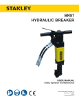
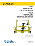
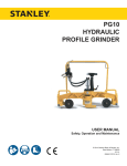
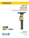
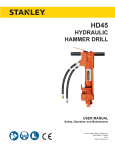
RD12
HYDRAULIC
RAIL DRILL
USER MANUAL
Safety, Operation and Maintenance
© 2014 Stanley Black & Decker, Inc.
New Britain, CT 06053
U.S.A.
32515 4/2015 Ver. 10
DECLARATION OF CONFORMITY
DECLARATION OF CONFORMITY
ÜBEREINSTIMMUNGS-ERKLARUNG
DECLARATION DE CONFORMITE CEE
DECLARACION DE CONFORMIDAD
DICHIARAZIONE DI CONFORMITA
Hydraulic Tools
______________________________________________________________________
I, the undersigned:
Ich, der Unterzeichnende:
Je soussigné:
El abajo firmante:
lo sottoscritto:
Weisbeck, Andy
Surname and First names/Familiennname und Vornamen/Nom et prénom/Nombre y apellido/Cognome e nome
hereby declare that the equipment specified hereunder:
bestätige hiermit, daß erklaren Produkt genannten Werk oder Gerät:
déclare que l’équipement visé ci-dessous:
Por la presente declaro que el equipo se especifica a continuación:
Dichiaro che le apparecchiature specificate di seguito:
Rail Drill, Hydraulic
1.
Category:
Kategorie:
Catégorie:
Categoria:
Categoria:
2.
Make/Marke/Marque/Marca/Marca
3.
Type/Typ/Type/Tipo/Tipo:
4.
Serial number of equipment:
Seriennummer des Geräts:
Numéro de série de l’équipement:
Numero de serie del equipo:
Matricola dell´attrezzatura:
Stanley
RD12101, RD12100
All
Has been manufactured in conformity with
Wurde hergestellt in Übereinstimmung mit
Est fabriqué conformément
Ha sido fabricado de acuerdo con
E’ stata costruita in conformitá con
Directive/Standards
Richtlinie/Standards
Directives/Normes
Directriz/Los Normas
Direttiva/Norme
No.
Nr
Numéro
No
n.
Approved body
Prüfung durch
Organisme agréé
Aprobado
Collaudato
EN ISO
EN
Machinery Directive
3744:2010
11148-3:2010
2006/42/EC:2006
Self
Self
Self
5.
Special Provisions:
None
Spezielle Bestimmungen:
Dispositions particulières:
Provisiones especiales:
Disposizioni speciali:
6.
Representative in the Union: Patrick Vervier, Stanley Dubuis 17-19, rue Jules Berthonneau-BP 3406 41034 Blois Cedex, France.
Vertreter in der Union/Représentant dans l’union/Representante en la Union/Rappresentante presso l’Unione
Done at/Ort/Fait à/Dado en/Fatto a Stanley Hydraulic Tools, Milwaukie, Oregon USA
Signature/Unterschrift/Signature/Firma/Firma
Position/Position/Fonction/Cargo/Posizione
2 ► RD12 User Manual
Director of Product Development
Date/Datum/le/Fecha/Data
1-4-11
TABLE OF CONTENTS
DECLARATION OF CONFORMITY...........................................................................................................................2
SAFETY SYMBOLS...................................................................................................................................................4
SAFETY PRECAUTIONS...........................................................................................................................................5
TOOL STICKERS & TAGS.........................................................................................................................................6
HOSE TYPES.............................................................................................................................................................7
HOSE RECOMMENDATIONS...................................................................................................................................8
FIGURE 1. TYPICAL HOSE CONNECTIONS........................................................................................................8
HTMA REQUIREMENTS............................................................................................................................................9
OPERATION.............................................................................................................................................................10
TEMPLATES & HOLE GUIDES...............................................................................................................................12
TOOL PROTECTION & CARE.................................................................................................................................15
TROUBLESHOOTING.............................................................................................................................................16
SPECIFICATIONS....................................................................................................................................................17
ACCESSORIES.......................................................................................................................................................17
RD12 PARTS ILLUSTRATION.................................................................................................................................18
RD12 PARTS LIST...................................................................................................................................................19
IMPORTANT
To fill out a Product Warranty Validation form, and for information on your warranty,
visit Stanleyhydraulics.com and select the Company tab, Warranty.
(NOTE: The warranty Validation record must be submitted to validate the warranty).
SERVICING: This manual contains safety, operation, and routine maintenance instructions. Stanley Hydraulic Tools
recommends that servicing of hydraulic tools, other than routine maintenance, must be performed by an authorized
and certified dealer. Please read the following warning.
WARNING
SERIOUS INJURY OR DEATH COULD RESULT FROM THE IMPROPER REPAIR OR
SERVICE OF THIS TOOL.
REPAIRS AND / OR SERVICE TO THIS TOOL MUST ONLY BE DONE BY AN
AUTHORIZED AND CERTIFIED DEALER.
For the nearest authorized and certified dealer, call Stanley Hydraulic Tools at the number listed on the back of this
manual and ask for a Customer Service Representative.
RD12 User Manual ◄ 3
SAFETY SYMBOLS
Safety symbols and signal words, as shown below, are used to emphasize all operator, maintenance and repair actions which, if not strictly followed, could result in a life-threatening situation, bodily injury or damage to equipment.
This is the safety alert symbol. It is used to alert you to potential personal injury
hazards. Obey all safety messages that follow this symbol to avoid possible
injury or death.
DANGER
This safety alert and signal word indicate an imminently hazardous situation
which, if not avoided, will result in death or serious injury.
WARNING
This safety alert and signal word indicate a potentially hazardous situation
which, if not avoided, could result in death or serious injury.
CAUTION
This safety alert and signal word indicate a potentially hazardous situation
which, if not avoided, could result in death or serious injury.
CAUTION
This signal word indicates a potentially hazardous situation which, if not avoided, may result in property damage.
NOTICE
This signal word indicates a situation which, if not avoided, will result in damage
to the equipment.
IMPORTANT
This signal word indicates a situation which, if not avoided, may result in damage to the equipment.
Always observe safety symbols. They are included for your safety and for the protection of the tool.
LOCAL SAFETY REGULATIONS
Enter any local safety regulations here. Keep these instructions in an area accessible to the operator and maintenance personnel.
4 ► RD12 User Manual
SAFETY PRECAUTIONS
Tool operators and maintenance personnel must always
comply with the safety precautions given in this manual
and on the stickers and tags attached to the tool and
hose.
These safety precautions are given for your safety. Review them carefully before operating the tool and before
performing general maintenance or repairs.
Supervising personnel should develop additional precautions relating to the specific work area and local
safety regulations. If so, place the added precautions in
the space provided in this manual.
The model RD12 Hydraulic Rail Drill will provide safe
and dependable service if operated in accordance with
the instructions given in this manual. Read and understand this manual and any stickers and tags attached
to the pressure washer and hose before operation. Failure to do so could result in personal injury or equipment
damage.
•
The operator must start in a work area without bystanders. Flying debris can cause serious injury.
•
Do not operate the tool unless thoroughly trained
or under the supervision of an instructor. Establish
a training program for all operators to ensure safe
operation.
•
Always wear personal protection equipment (PPE)
such as goggles, safety shoes, head, eye, breathing, and ear protection when operating the tool. Use
gloves and aprons when necessary.
•
The operator must be familiar with all prohibited
work areas such as excessive slopes and dangerous terrain conditions.
•
Do not inspect, clean or replace the drill bit or any
part(s) if the hydraulic power source is connected.
Do not inspect or clean the tool while the hydraulic
power source is connected. Accidental engagement
of the tool can cause serious injury.
•
Always connect hoses to the tool hose couplers before energizing the hydraulic power source. Be sure
all hose connections are tight and are in good condition.
•
Do not operate the tool at oil temperatures above
140 °F/60 °C. Operation at higher temperatures can
cause higher than normal temperatures at the tool
which can result in operator discomfort.
•
Never wear loose clothing or unrestrained long hair
that can get entangled in the working parts of the
tool.
•
To avoid personal injury or equipment damage, all
tool repair, maintenance and service must only be
performed by authorized and properly trained personnel.
•
The hydraulic circuit control valve must be in the
OFF position when coupling or uncoupling the tool.
Wipe all couplers clean before connecting. Failure
to do so may result in damage to the quick couplers
and cause overheating. Use only lint-free cloths.
•
Never transport or carry the tool with the unit energized.
•
Use proper lifting techniques when handling the
tool. Do not overreach. Maintain proper footing and
balance at all times.
•
Keep hands and fingers away from rotating parts.
•
Do not operate a damaged, improperly adjusted or
incompletely assembled tool.
•
Do not exceed the rated limits of the tool or use the
tool for applications beyond its design capacity.
•
Always keep critical tool markings, such as labels
and warning stickers legible.
•
Check fasteners tightness often and before each
use daily.
•
Never operate the tool if you cannot be sure that
underground utilities are not present. Underground
electrical utilities present an electrocution hazard.
Underground gas utilities present an explosion hazard. Other underground utilities may present other
hazards.
•
Always replace parts with replacement parts recommended by Stanley Hydraulic Tools.
•
Warning: hydraulic fluid under pressure could cause
skin injection injury. If you are injured by hydraulic
fluid get medical attention immediately.
RD12 User Manual ◄ 5
TOOL STICKERS & TAGS
28788
Manual
Sticker
11207
Circuit Type D
Sticker
51296
Sound Power
Sticker
31096
RD12 Model Sticker
31049
Eye Protection Sticker
WARNING
PINCH POINT
STAY CLEAR OF ALL MOVING PARTS
25610
Railroad Help Desk Sticker
31096
RD12 Model Sticker
17572
Pinch Point Warning Sticker
31096
RD12 Model Sticker
NOTE:
THE INFORMATION LISTED
ON THE STICKERS SHOWN,
MUST BE LEGIBLE AT ALL
TIMES.
REPLACE DECALS IF
THEY BECOME WORN OR
DAMAGED. REPLACEMENTS
ARE AVAILABLE FROM
YOUR LOCAL STANLEY
DISTRIBUTOR.
The safety tag (P/N 15875) at right is
attached to the tool when shipped from
the factory. Read and understand the
safety instructions listed on this tag before
removal. We suggest you retain this tag and
attach it to the tool when not in use.
D A N G E R
1.
FAILURE TO USE HYDRAULIC HOSE LABELED AND CERTIFIED AS NON-CONDUCTIVE WHEN USING HYDRAULIC
TOOLS ON OR NEAR ELECTRICAL LINES MAY RESULT IN
DEATH OR SERIOUS INJURY.
BEFORE USING HOSE LABELED AND CERTIFIED AS NONCONDUCTIVE ON OR NEAR ELECTRIC LINES BE SURE THE
HOSE IS MAINTAINED AS NON-CONDUCTIVE. THE HOSE
SHOULD BE REGULARLY TESTED FOR ELECTRIC CURRENT LEAKAGE IN ACCORDANCE WITH YOUR SAFETY
DEPARTMENT INSTRUCTIONS.
2.
A HYDRAULIC LEAK OR BURST MAY CAUSE OIL INJECTION INTO THE BODY OR CAUSE OTHER SEVERE
PERSONAL INJURY.
A.
DO NOT EXCEED SPECIFIED FLOW AND PRESSURE
FOR THIS TOOL. EXCESS FLOW OR PRESSURE MAY
CAUSE A LEAK OR BURST.
B.
DO NOT EXCEED RATED WORKING PRESSURE OF
HYDRAULIC HOSE USED WITH THIS TOOL. EXCESS
PRESSURE MAY CAUSE A LEAK OR BURST.
C. CHECK TOOL HOSE COUPLERS AND CONNECTORS
DAILY FOR LEAKS. DO NOT FEEL FOR LEAKS WITH
YOUR HANDS. CONTACT WITH A LEAK MAY RESULT
IN SEVERE PERSONAL INJURY.
D A N G E R
D. DO NOT LIFT OR CARRY TOOL BY THE HOSES. DO
NOT ABUSE HOSE. DO NOT USE KINKED, TORN OR
DAMAGED HOSE.
3.
MAKE SURE HYDRAULIC HOSES ARE PROPERLY CONNECTED TO THE TOOL BEFORE PRESSURING SYSTEM.
SYSTEM PRESSURE HOSE MUST ALWAYS BE CONNECTED TO TOOL “IN” PORT. SYSTEM RETURN HOSE
MUST ALWAYS BE CONNECTED TO TOOL “OUT” PORT.
REVERSING CONNECTIONS MAY CAUSE REVERSE
TOOL OPERATION WHICH CAN RESULT IN SEVERE
PERSONAL INJURY.
4.
DO NOT CONNECT OPEN-CENTER TOOLS TO CLOSEDCENTER HYDRAULIC SYSTEMS. THIS MAY RESULT IN
LOSS OF OTHER HYDRAULIC FUNCTIONS POWERED BY
THE SAME SYSTEM AND/OR SEVERE PERSONAL INJURY.
5.
BYSTANDERS MAY BE INJURED IN YOUR WORK AREA.
KEEP BYSTANDERS CLEAR OF YOUR WORK AREA.
6.
WEAR HEARING, EYE, FOOT, HAND AND HEAD PROTECTION.
7.
TO AVOID PERSONAL INJURY OR EQUIPMENT DAMAGE,
ALL TOOL REPAIR MAINTENANCE AND SERVICE MUST
ONLY BE PERFORMED BY AUTHORIZED AND PROPERLY
TRAINED PERSONNEL.
I M P O R T A N T
I M P O R T A N T
READ OPERATION MANUAL AND
SAFETY INSTRUCTIONS FOR THIS
TOOL BEFORE USING IT.
READ OPERATION MANUAL AND
SAFETY INSTRUCTIONS FOR THIS
TOOL BEFORE USING IT.
USE ONLY PARTS AND REPAIR
PROCEDURES APPROVED BY
STANLEY AND DESCRIBED IN THE
OPERATION MANUAL.
USE ONLY PARTS AND REPAIR
PROCEDURES APPROVED BY
STANLEY AND DESCRIBED IN THE
OPERATION MANUAL.
TAG TO BE REMOVED ONLY BY
TOOL OPERATOR.
TAG TO BE REMOVED ONLY BY
TOOL OPERATOR.
SEE OTHER SIDE
SEE OTHER SIDE
SAFETY TAG P/N 15875 (Shown smaller then actual size)
6 ► RD12 User Manual
HOSE TYPES
The rated working pressure of the hydraulic hose must be equal to or higher than the relief valve setting on the hydraulic system. There are three types of hydraulic hose that meet this requirement and are authorized for use with
Stanley Hydraulic Tools. They are:
Certified non-conductive — constructed of thermoplastic or synthetic rubber inner tube, synthetic fiber braid
reinforcement, and weather resistant thermoplastic or synthetic rubber cover. Hose labeled certified nonconductive is the only hose authorized for use near electrical conductors.
Wire-braided (conductive) — constructed of synthetic rubber inner tube, single or double wire braid reinforcement, and weather resistant synthetic rubber cover. This hose is conductive and must never be used near
electrical conductors.
Fabric-braided (not certified or labeled non-conductive) — constructed of thermoplastic or synthetic rubber inner tube, synthetic fiber braid reinforcement, and weather resistant thermoplastic or synthetic rubber cover. This
hose is not certified non-conductive and must never be used near electrical conductors.
HOSE SAFETY TAGS
To help ensure your safety, the following DANGER tags are attached to all hose purchased from Stanley Hydraulic
Tools. DO NOT REMOVE THESE TAGS.
If the information on a tag is illegible because of wear or damage, replace the tag immediately. A new tag may be
obtained from your Stanley Distributor.
D A N G E R
D A N G E R
1.
FAILURE TO USE HYDRAULIC HOSE LABELED AND CERTIFIED AS NON-CONDUCTIVE
WHEN USING HYDRAULIC TOOLS ON OR NEAR ELECTRIC LINES MAY RESULT IN
DEATH OR SERIOUS INJURY.
FOR PROPER AND SAFE OPERATION MAKE SURE THAT YOU HAVE BEEN PROPERLY TRAINED IN CORRECT PROCEDURES REQUIRED FOR WORK ON OR AROUND
ELECTRIC LINES.
2.
BEFORE USING HYDRAULIC HOSE LABELED AND CERTIFIED AS NON-CONDUCTIVE
ON OR NEAR ELECTRIC LINES. WIPE THE ENTIRE LENGTH OF THE HOSE AND FITTING WITH A CLEAN DRY ABSORBENT CLOTH TO REMOVE DIRT AND MOISTURE AND
TEST HOSE FOR MAXIMUM ALLOWABLE CURRENT LEAKAGE IN ACCORDANCE WITH
SAFETY DEPARTMENT INSTRUCTIONS.
3.
DO NOT EXCEED HOSE WORKING PRESSURE OR ABUSE HOSE. IMPROPER USE
OR HANDLING OF HOSE COULD RESULT IN BURST OR OTHER HOSE FAILURE.
KEEP HOSE AS FAR AWAY AS POSSIBLE FROM BODY AND DO NOT PERMIT DIRECT
CONTACT DURING USE. CONTACT AT THE BURST CAN CAUSE BODILY INJECTION
AND SEVERE PERSONAL INJURY.
4.
HANDLE AND ROUTE HOSE CAREFULLY TO AVOID KINKING, ABRASION, CUTTING, OR
CONTACT WITH HIGH TEMPERATURE SURFACES. DO NOT USE IF KINKED. DO NOT
USE HOSE TO PULL OR LIFT TOOLS, POWER UNITS, ETC.
5.
CHECK ENTIRE HOSE FOR CUTS CRACKS LEAKS ABRASIONS, BULGES, OR DAMAGE TO COUPLINGS IF ANY OF THESE CONDITIONS EXIST, REPLACE THE HOSE
IMMEDIATELY. NEVER USE TAPE OR ANY DEVICE TO ATTEMPT TO MEND THE HOSE.
6.
AFTER EACH USE STORE IN A CLEAN DRY AREA.
SEE OTHER SIDE
SIDE 1
SEE OTHER SIDE
(Shown smaller than actual size)
DO NOT REMOVE THIS TAG
DO NOT REMOVE THIS TAG
THE TAG SHOWN BELOW IS ATTACHED TO “CERTIFIED NON-CONDUCTIVE” HOSE
SIDE 2
D A N G E R
D A N G E R
1.
DO NOT USE THIS HYDRAULIC HOSE ON OR NEAR ELECTRIC LINES. THIS HOSE IS
NOT LABELED OR CERTIFIED AS NON-CONDUCTIVE. USING THIS HOSE ON OR NEAR
ELECTRICAL LINES MAY RESULT IN DEATH OR SERIOUS INJURY.
5.
CHECK ENTIRE HOSE FOR CUTS CRACKS LEAKS ABRASIONS, BULGES, OR DAMAGE TO
COUPLINGS IF ANY OF THESE CONDITIONS EXIST, REPLACE THE HOSE IMMEDIATELY.
NEVER USE TAPE OR ANY DEVICE TO ATTEMPT TO MEND THE HOSE.
2.
FOR PROPER AND SAFE OPERATION MAKE SURE THAT YOU HAVE BEEN PROPERLY
TRAINED IN CORRECT PROCEDURES REQUIRED FOR WORK ON OR AROUND ELECTRIC LINES.
6.
AFTER EACH USE STORE IN A CLEAN DRY AREA.
3.
DO NOT EXCEED HOSE WORKING PRESSURE OR ABUSE HOSE. IMPROPER USE OR
HANDLING OF HOSE COULD RESULT IN BURST OR OTHER HOSE FAILURE. KEEP HOSE
AS FAR AWAY AS POSSIBLE FROM BODY AND DO NOT PERMIT DIRECT CONTACT
DURING USE. CONTACT AT THE BURST CAN CAUSE BODILY INJECTION AND SEVERE
PERSONAL INJURY.
4.
HANDLE AND ROUTE HOSE CAREFULLY TO AVOID KINKING, CUTTING, OR CONTACT
WITH HIGH TEMPERATURE SURFACES. DO NOT USE IF KINKED. DO NOT USE HOSE TO
PULL OR LIFT TOOLS, POWER UNITS, ETC.
DO NOT REMOVE THIS TAG
DO NOT REMOVE THIS TAG
THE TAG SHOWN BELOW IS ATTACHED TO “CONDUCTIVE” HOSE.
SEE OTHER SIDE
SEE OTHER SIDE
SIDE 1
SIDE 2
(Shown smaller than actual size)
RD12 User Manual ◄ 7
8 ► RD12 User Manual
All hydraulic hose must meet or exceed
specifications as set forth by SAE J517.
All hydraulic hose must have at least a rated
minimum working pressure equal to the maximum hydraulic system relief valve setting.
This chart is intended to be used for hydraulic
tool applications only based on Stanley Hydraulic Tools tool operating requirements and
should not be used for any other applications.
The chart to the right shows recommended
minimum hose diameters for various hose
lengths based on gallons per minute (gpm)/
liters per minute (lpm). These recommendations are intended to keep return line pressure
(back pressure) to a minimum acceptable level to ensure maximum tool performance.
Tool to Hydraulic Circuit Hose
Recommendations
15-34
MM
Inside Diameter
INCH
USE
(Press/Return)
PSI
up to 10
up to 3
3/8
10
Both
2250
49-60
13-16
FLOW >>>
RETURN
<<< FLOW
PRESSURE
26-100
up to 25
100-200
51-100
up to 50
100-300
51-100
up to 50
26-100
up to 25
8-30
up to 8
30-60
15-30
up to 15
30-90
15-30
up to 15
7.5-30
up to 7.5
Figure 1. Typical Hose Connections
49-60
38-49
10-13
13-16
19-40
5-10.5
38-49
19-40
5-10.5
10-13
19-40
5-10.5
38-49
15-23
10-13
15-23
4-6
19
25.4
16
19
19
25.4
5/8
3/4
3/4
1
19
3/4
1
16
3/4
16
19
3/4
5/8
16
5/8
5/8
16
13
13
10
5/8
1/2
1/2
3/8
Return
Pressure
Return
Pressure
Return
Pressure
Return
Pressure
Both
Return
Pressure
Both
Both
Both
Both
2500
2500
2500
2500
2500
2500
2500
2500
2500
2500
2500
2500
2500
2500
2500
175
175
175
175
175
175
175
175
175
175
175
175
175
175
175
155
BAR
Min. Working Pressure
Certified Non-Conductive Hose - Fiber Braid - for Utility Bucket Trucks
METERS
Hose Lengths
FEET
Conductive Hose - Wire Braid or Fiber Braid -DO NOT USE NEAR ELECTRICAL CONDUCTORS
4-6
4-9
LPM
Oil Flow
GPM
HOSE RECOMMENDATIONS
HTMA / EHTMA REQUIREMENTS
HTMA / EHTMA REQUIREMENTS
HTMA
HYDRAULIC SYSTEM REQUIREMENTS
TYPE I
Nominal Operating Pressure
(at the power supply outlet)
4-6 gpm
(15-23 lpm)
1500 psi
(103 bar)
TOOL TYPE
TYPE II
TYPE RR
7-9 gpm
(26-34 lpm)
1500 psi
(103 bar)
9-10.5 gpm
(34-40 lpm)
1500 psi
(103 bar)
System relief valve setting
(at the power supply outlet)
2100-2250 psi
(145-155 bar)
2100-2250 psi
(145-155 bar)
2200-2300 psi
(152-159 bar)
2100-2250 psi
(145-155 bar)
Maximum back pressure
(at tool end of the return hose)
250 psi
(17 bar)
250 psi
(17 bar)
250 psi
(17 bar)
250 psi
(17 bar)
Measured at a max. fluid viscosity of:
(at min. operating temperature)
400 ssu*
400 ssu*
400 ssu*
400 ssu*
(82 centistokes) (82 centistokes) (82 centistokes) (82 centistokes)
Temperature: Sufficient heat rejection
capacity to limit max. fluid temperature to:
(at max. expected ambient temperature)
140° F
(60° C)
Flow Range
140° F
(60° C)
140° F
(60° C)
TYPE III
11-13 gpm
(42-49 lpm)
1500 psi
(103 bar)
140° F
(60° C)
3 hp
5 hp
6 hp
7 hp
Min. cooling capacity at a temperature
(2.24 kW)
(3.73 kW)
(5.22 kW)
(4.47 kW)
difference of between ambient and fluid
40° F
40° F
40° F
40° F
temps
(22° C)
(22° C)
(22° C)
(22° C)
NOTE:
Do not operate the tool at oil temperatures above 140° F (60° C). Operation at higher temperatures can cause operator
discomfort at the tool.
Filter
Min. full-flow filtration
Sized for flow of at least:
(For cold temp. startup and max.
dirt-holding capacity)
25 microns
30 gpm
(114 lpm)
Hydraulic fluid Petroleum based
(premium grade, anti-wear, non-conductive)
Viscosity (at min. and max. operating temps)
100-400 ssu*
25 microns
30 gpm
(114 lpm)
25 microns
30 gpm
(114 lpm)
100-400 ssu*
100-400 ssu*
(20-82 centistokes)
25 microns
30 gpm
(114 lpm)
100-400 ssu*
NOTE:
When choosing hydraulic fluid, the expected oil temperature extremes that will be experienced in service determine the
most suitable temperature viscosity characteristics. Hydraulic fluids with a viscosity index over 140 will meet the requirements
over a wide range of operating temperatures.
*SSU = Saybolt Seconds Universal
EHTMA
HYDRAULIC SYSTEM
REQUIREMENTS
CLASSIFICATION
B
C
D
Nominal Operating Pressure
(at the power supply outlet)
3.5-4.3 gpm
(13.5-16.5 lpm)
1870 psi
(129 bar)
4.7-5.8 gpm
(18-22 lpm)
1500 psi
(103 bar)
7.1-8.7 gpm
(27-33 lpm)
1500 psi
(103 bar)
9.5-11.6 gpm
(36-44 lpm)
1500 psi
(103 bar)
11.8-14.5 gpm
(45-55 lpm)
1500 psi
(103 bar)
System relief valve setting
(at the power supply outlet)
2495 psi
(172 bar)
2000 psi
(138 bar)
2000 psi
(138 bar)
2000 psi
(138 bar)
2000 psi
(138 bar)
Flow Range
NOTE: These are general hydraulic system requirements. See tool specification page for tool specific requirements
RD12 User Manual ◄ 9
OPERATION
PREOPERATION PROCEDURES
PREPARATION FOR INITIAL USE
The tool as shipped has no special unpacking or assembly requirements prior to usage. Inspection to assure the
tool was not damaged in shipping and that it does not
contain packing debris is all that is required. Otherwise,
the tool may be connected to a hydraulic source upon
receipt.
CHECK HYDRAULIC POWER SOURCE
1. Using a calibrated flowmeter and pressure gauge,
check that the hydraulic power source develops a
flow of 8–10 gpm/30–38 lpm at 2000 psi/140 bar.
2. Make certain the hydraulic power source is equipped
with a relief valve set to open at 2200–2300 psi/152–
159 bar ma×imum.
3. Make certain that the power source return pressure
does not e×ceed 250 psi/17 bar.
2. If operating the rail drill at temperatures below
32 °F/0 °C, fill the coolant can with a mi×ture of 50%
ordinary tap water and 50% biodegradable antifreeze.
3. Pressurize the coolant can using the carrying handle/pump.
4. Connect the coolant can assembly to the rail drill using the supplied quick-disconnect coupler.
OPERATING PROCEDURES
1. Observe all safety precautions.
2. Make sure the drill bit you intend to use contains
carbide inserts with good cutting surfaces. If the
surfaces are worn or chipped, unscrew the retaining
screw and rotate the insert to a good cutting surface.
If the inserts do not contain a good cutting surface
on one of the four sides, replace the inserts. Make
sure the bit holder is not damaged.
CONNECT HOSES
3. Install the drill bit into the piston machining assembly (24) and then turn it clockwise until it stops.
1. Wipe all hose couplers with a clean lint-free cloth
before making connections.
RAIL TEMPLATES & HOLE GUIDES
2. Connect the hoses from the hydraulic power source
to the hose couplers on the tool. It is a good practice to connect the return hose first and disconnect
it last to minimize or avoid trapped pressure within
the tool.
The RD12 must be used with rail templates and hole
guides. See the chart at the end of this section for
selections of rail templates and hole guides.
3. Observe flow indicators stamped on hose couplers
to be sure that oil will flow in the proper direction.
The female coupler is the inlet coupler.
4. Observe the IN and OUT port lettering on the valve
block assembly to ensure that the hydraulic flow is in
the proper direction. The IN port lettering indicates
the inlet (pressure) side.
NOTE:
The pressure increase in uncoupled hoses left in the
sun may result in making them difficult to connect.
When possible, connect the free ends of operating
hoses together.
USING COOLANT
The RD12 rail drill is equipped with a separate coolant
can assembly that is used to deliver coolant to the drill
bit. Follow the instructions below to use the coolant can
assembly with the rail drill:
1. If operating the rail drill at temperatures above
32 °F/0 °C, fill the coolant can with ordinary tap water.
10 ► RD12 User Manual
NOTE:
1. Install a hole guide assembly onto the rail and position it where you want to drill.
2. Install templates onto the rail drill with the rail size
facing the rail.
NOTE:
To avoid drill bit damage, make sure the drill bit/piston assembly is fully retracted prior to placing the
RD12 on the rail.
3. Set the rail drill over the hole guide on the rail so that
the templates are nested between the ball and the
base of the rail and the adjustment screw (52) fits in
a slot in the hole guide.
4. Adjust the threaded shaft (44) until there is no movement of the rail drill as it sits on the rail and the hole
guide. Wiggle the RD12 to remove all looseness.
Then lift the handle (49) up and turn the threaded
shaft (44) clockwise appro×imately 1/2 turn. Push
the handle (49) down hard to firmly clamp the RD12
to the rail.
OPERATION
TO BEGIN DRILLING
STORAGE
NOTE:
•
Clean the tool thoroughly.
Do not operate the drill in the fully advanced position for more than 5-10 seconds at one time.
•
Remove the drill bit.
1. Engage the control valve on the hydraulic power
source to the ON position.
•
Advance the piston .250 in./6 mm.
•
Drain water from the tool.
•
Retract the piston
•
Store in a dry area.
2. To begin drilling, move the control lever on the rail
drill toward the “drill bit” symbol. The drill bit will turn
and advance simultaneously. Make sure water is
spraying from the bit.
TO STOP DRILLING
Move the control lever to the “0” mark to stop the rail
drill.
TO RETRACT THE DRILL BIT
Move the control lever to the “retract” symbol to retract
the drill bit.
COLD WEATHER OPERATION
Preheat the hydraulic fluid at low engine speed. When
using the normally recommended fluids, fluid temperature should be at or above 50 °F/10 °C before use.
Use a biodegradeable antifreeze solution such as windshield antifreeze in the spray can.
Drain water from the drill when finished using.
Retract Symbol
Figure 2. Retract the Drill Bit
REMOVING THE DRILL BIT
1. Uncouple the water hose from the rail drill.
2. Move the hydraulic circuit control valve to the OFF
position and disconnect from the power supply.
3. From the bit end, turn the bit counter clockwise and
pull it out.
RD12 User Manual ◄ 11
TEMPLATES & HOLE GUIDES
RAIL SIZE
RD12 DRILL TEMPLATE SETS:
DOUBLE SIDED/
(SINGLE SIDED)
60 ASCE (6040)#
^(34525)
USA
65 ASCE (6540)#
^(35975)
USA
68GN
(52636)
70 ASCE #
^(49246)
72 CHI & NW (7250)
^(35876)
75 ASCE (7540)
^34262
75 GRT. NO.-1893
^(35701)
USA
75 U PAC C.R.S.#
^(36001)
USA
77 1/2 GRT. NO. #
^33720 ^(35876)
80 ASCE (8040) #
^(35626)/^38660
80 GRT. NOR.#
^33720 ^(35876)
38644 [2 1/8 × 4 1/2 × 7]
USA
85 ASCE STD (8504 /8540)
^(34915)
[2 7/16 × 7 × 6] & ^(35358) [2 7/16 × 6× 6]
USA
85 CAN. PAC. (8524)#
^(35628 HD)
85 CP HEAD FREE (37337)
^(37337 HD)
85 GRT. NOR.#
^33720 ^(35876)
85PS
^37139
USA
85 SOO LINE (8520)
^(35630 HD)
USA
90 ARA-B (9030) 2 11/32 ELEVATION
^34263
USA
90 ASCE (9040)
^(36046)
USA
90 C&NW (9035)
^(35715)
90 GN
^33720
35358 (2 7/16 × 6 )
USA
90 RA (ARA-A)(9020) 90 SF
31978 / (31984)/35105 (65948 HD)
22631 [2 11/16 × 5 1/2 × 5 1/2] ^34680 [213/32 × 5 × 5 ]
USA
100 ARA-A (10020)
^34159 / ^35438/^38660
^34526 [ 3 × 6 ]
USA
100 ARA-B (10030) / 100-8
^(34916)
USA
100 RA HEAD FREE
^(37367)
USA
100 RE STD (10025) 2 45/64 ELEVATION
^34263 (65959 HD)
100 RE HEAD FREE (37341)
^(37341 HD)
100 CN&W (10035)
^(34982)
39229 [2-31/32 × 6]
USA
100 GRT. NO.
^(35633)
38645 [2 7/16 × 7]
USA
100PS
^37139
USA
100 ASCE (10040)
^(65761 HD)
USA
105 DUDLEY (10524)
^(34917)
USA
105 DUDLEY (OFFSET)
^(58508 OFFSET TEMPLATE)
58468 [2 × 4 3/4 × 4 3/4]
USA
110 GRT NO (11036)
^(35973)
38645 [2 7/16 × 7]
USA
110 RE GUARD RAIL
^(35151)
110 RE (11025) 2 5/8 ELEVATION
^(34597)
110 RE (11025) 2 53/64 ELEVATION
^(38683)
112 RE (11228) 2 7/8” ELEVATION
33721/31979/31980/35105
(31985)(62201 HD)
^33687 [2 1/2 × 6 1/2 × 6 1/2]
USA
112TR
^33721
^33687 [2 1/2 × 6 1/2 × 6 1/2]
USA
113 HEAD FREE
^(34598)
115 AREA RETARDER 3.484 FI×ED
ELEVATION
(34882 FI×ED) (34935 ADJ.)
34912 FI×ED / 34933 ADJ. [3 1/2]
USA
115 AREA (11525) 2 7/8” ELEVATION
31979/31980/35105/^35438
(31985)(62201 HD)
22625 [3 1/2 × 6 × 6]
USA
12 ► RD12 User Manual
GUIDE ASSY P/N: ING (MM)/[INCHES]
38644 [2 1/8 × 4 1/2 × 7]
COUNTRY
USA
USA
USA
22631 [2 11/16 × 5 1/2 × 5 1/2]
38644 [2 1/8 × 4 1/2 × 7]
USA
USA
USA
USA
USA
[2 7/16 × 5]
USA
USA
36037 [2 1/2 × 6 × 6 ]
USA
USA
USA
^35357 [2 23/32 × 5 1/2]
USA
USA
USA
TEMPLATES & HOLE GUIDES
RAIL SIZE
RD12 DRILL TEMPLATE SETS:
DOUBLE SIDED/
(SINGLE SIDED)
115 RE GUARD RAIL 3 1/32” ELEVATION
^(35153)
119 AREA (11922) 2 7/8” ELEVATION
31979/31980/35105/ (31985)
(62201 HD)
22625 [3 1/2 × 6 × 6]
USA
122 C.B. & O.
^34159(32279)
22625 [3 1/2 × 6 × 6]
USA
127 DUDLEY (12723)
^34264
22625 [3 1/2 × 6 × 6]
USA
129 TR
^(35003)
USA
130 AREA (13025)
^(36048)
USA
130 AREA HEAD FREE (3 1/16
ELEVATION)
^(41772)
USA
130 AREA HEAD FREE (2 15/16
ELEVATION)
^(38579)
USA
130 AREA HEAD FREE (2 3/4 ELEVATION)
^(38643)
130 PS (13031)
^(34918)
131 RE (13128)
31980/31981 / (31986)(62203 HD)
^33687 [2 1/2 × 6 1/2 × 6 1/2]
USA
131 RE-M
^34264
22625 [3 1/2 × 6 × 6]
USA
132 HEAD FREE
^(34599)
132 AREA (13225)
31980/31981 / (31986)(62203 HD)
132 RE GUARD RAIL
^(35155)
GUIDE ASSY P/N: ING (MM)/[INCHES]
COUNTRY
USA
USA
USA
22625 [3 1/2 × 6 × 6]
USA
USA
133 AREA (13331)
31979 / 31981 / (31987)
22625 [3 1/2 × 6 × 6]
USA
136 AREA (13622) (STD. 3 3/32”
ELEVATION)
31980/31981 / (31986)(62203 HD)
22625 [3 1/2 × 6 × 6]
USA
136 AREA (3” ELEVATION)
(44977)
44975 [2-23/32 × 6 × 7]
USA
136 RE GUARD RAIL (3 9/32 ELEVATION)
^(35155)
USA
136 RE STOCK RAIL (3 11/32 ELEVATION)
(66945 HD)
USA
136 LVH
(62412)
USA
136 LV (13633)
(65075)
140 AREA (14031)
31978 / (31988)
22625 [3 1/2 × 6 × 6]
USA
141 AREA
(43674) (65963 HD)
22625 [3 1/2 × 6 × 6]
USA
152 PS
^(43576)
USA
155 PS
^(43578)
USA
41 KG AS1085
^(35353)
41773 (62 × 127 × 127)
AUSTRALIA
47 KG AS1085
^(35353)
41773 (62 × 127 × 127)
AUSTRALIA
50 KG AS1085
^(35351)
41774 (88 × 130 × 130)
AUSTRALIA
53 KG (107#) AS1085
^(34185)
41774 (88 × 130 × 130)
AUSTRALIA
60 KG AS1085.1
^(34187)
41774 (88 × 130 × 130)
AUSTRALIA
TR-32 (SEE 65 ASCE)
^(35975)
TR-37 (SEE 75ASCE)
^34262
22631 [2 11/16 × 5 1/2 × 5 1/2]
BRAZIL
TR-45 (SEE 90ARA-A)
^34262
22631 [2 11/16 × 5 1/2 × 5 1/2]
BRAZIL
USA
BRAZIL
TR-50 (SEE 100RE)
BRAZIL
TR-57 (SEE 115AREA)
BRAZIL
TR-68 (SEE 136AREA)
BRAZIL
50 KG N
31975 (43583)
29963 (77 × 130 ×130)
CHINA
60 KG
(69512)
69510 (76 × 140 × 140)
CHINA
46 KG U 33
31973
50 KG U 50
31974
LP48
31973
FRANCE
29434 (60 × 170)
FRANCE
FRANCE
RD12 User Manual ◄ 13
TEMPLATES & HOLE GUIDES
RAIL SIZE
RD12 DRILL TEMPLATE SETS:
DOUBLE SIDED/
(SINGLE SIDED)
GUIDE ASSY P/N: ING (MM)/[INCHES]
COUNTRY
60 KG UIC
31974
29434 (60 × 170)
FRANCE
S49
31976 / (31982)
31772 (46 × 165)
GERMANY
S54
31976 / (31982)
31772 (46 × 165)
GERMANY
60 KG UIC/UNI
31976 / (31983)
31772 (46 × 165)
GERMANY
54 KG UIC
^34261
HOLLAND
NP46
^34261
HOLLAND
I.R.S. 52KG
(66830)
66831 (80 × 166)
INDIA
60KG UIC
(31983)
66831 (80 × 166)
INDIA
50 KG UNI **
31976 / (31982)
30675 (47 × 165)
ITALY
60 KG UIC/UNI
31976 / (31983)
30675 (47 × 165)
ITALY
60 KG
31975
29963 (77 × 130 × 130)
JAPAN
50 KG N
31975 (43583)
29963 (77 × 130 × 130)
JAPAN
P50
(66321 HD)
66324 (65 × 150 × 140)
RUSSIA
P65
(66323 HD)
66326 (95 × 220)
RUSSIA
54KG UIC
^34261
^32276 (58 × 170)
SPAIN
37 KG JIS/JRS
^(43580)
44927 (60.5 × 127)
TAIWAN
50 KG N
31975 ^(43583)
29963 (77 × 130 × 130)
TAIWAN
60 KG UIC
31976
31772 (46 × 165)
TAIWAN
87LB B.H.
^(35251)
90LB B.H.
^(35255)
^(35284) (60 × 114)
UK
92LB F.B.
^(35257)
^(35283) (54 × 114)
UK
BS 95 B.H
31977
UK
95LB F.B. MARK A
^(35249)
UK
95LB F.B. MARK B
^(35470)
UK
36 KG U 33
ITALY
UK
98
UK
109BR
UK
BS 113A (54KG UIC) 65MM HOLE
ELEVATION
31977
31779 (60.32 × 127 × 203)
UK
54KG UIC (BS 113A) 70MM HOLE
ELEVATION
34261
38889 (65 × 200)
UK
UIC60 INSULATED
(71558)
71459 (62 × 170 × 170)
UK
CIE 50
^(39233)
39236 (57 × 120)
UK
RILC/RILR
*(E32009)
EUROPE
RI60/RI60N
*(E32010)
EUROPE
PH37
*(E32011)
EUROPE
* = NOT RELEASED, TEMPLATE ONLY NOT A SET
^ = AVAILABLE BY SPECIAL ORDER ONLY
# = REQUIRES CHAMFERED CYLINDER CASTING
14 ► RD12 User Manual
TOOL PROTECTION & CARE
NOTICE
In addition to the Safety Precautions found in
this manual, observe the following for equipment
protection and care.
•
Make sure all couplers are wiped clean before connection.
•
Tool repair should be performed by e×perienced
personnel only.
•
The hydraulic circuit control valve must be in the
OFF position when coupling or uncoupling hydraulic
tools. Failure to do so may result in damage to the
quick couples and cause overheating of the hydraulic system.
•
Make certain that the recommended relief valves
are installed in the pressure side of the system.
•
Do not use the tool for applications for which it was
not intended.
•
Always store the tool in a clean dry space, safe from
damage or pilferage.
•
Make sure the circuit PRESSURE hose (with male
quick disconnect) is connected to the IN port. The
circuit RETURN hose (with female quick disconnect)
is connected to the opposite port. Do not reverse circuit flow. This can cause damage to internal seals.
•
Always replace hoses, couplings and other parts
with replacement parts recommended by Stanley
Hydraulic Tools. Supply hoses must have a minimum working pressure rating of 2500 psi/172 bar.
•
Do not e×ceed the rated flow (see Specifications) in
this manual for correct flow rate and model number.
Rapid failure of the internal seals may result.
•
Always keep critical tool markings, such as warning
stickers and tags legible.
RD12 User Manual ◄ 15
TROUBLESHOOTING
If symptoms of poor performance develop, the following chart can be used as a guide to correct the problem.
When diagnosing problems with operation of the drill, always check that the hydraulic power source is supplying
the correct hydraulic flow and pressure to the tool as listed in the specifications. Use a flowmeter known to be accurate. Check the flow with the hydraulic oil temperature at least 80 °F/27 °C.
PROBLEM
Drill does not run.
Drill bit dulls quickly.
Drill moves on rail during drilling
operation.
Drill vibrates during drilling.
Inserts chipped.
Insert screw difficult to remove.
16 ► RD12 User Manual
CAUSE
SOLUTION
Hydraulic power source not
functioning.
Check power source for proper flow and
pressure, 8–10 gpm/30–38 lpm, 2000
psi/140 bar.
Couplers or hoses blocked.
Locate and remove restriction.
Hydraulic motor failure.
Inspect and repair.
Hydraulic lines not connected.
Connect lines.
Incorrect oil flow.
Check that 8–10 gpm/30–38 lpm at 2000
psi/140 bar is available at the rail drill.
Using insufficient amount of
coolant.
Rotate or replace insert. Increase flow of
coolant. Make sure pressure tank is fully
pumped up. Check for plugged water port
in drill bit. Check for a clogged inlet filter.
Remove pipe plug in end cap and flush
with water. Remove end cap and clean
filter.
Not clamped properly.
See clamping instructions.
Wrong templates.
Use correct templates and verify fit to rail.
Template knob(s) not tight
Tighten knobs securely.
Inserts dull or damaged.
Rotate or replace inserts.
Template knob(s) loose.
Tighten knobs securely.
Not clamped properly.
See clamping instructions.
Some chipping is normal,
particularly on the inside insert.
Rotate or replace if poor hole finish is
noted.
Incorrect template.
Use correct template and verify fit.
Using insufficient amount of
coolant.
Rotate or replace insert. Increase flow of
coolant. Make sure pressure tank is fully
pumped up. Check for plugged water port
in drill bit. Check for a clogged inlet filter.
Remove pipe plug in end cap and flush
with water. Remove end cap and clean
filter.
Not clamped properly.
See clamping instructions.
Template knob(s) loose
Tighten knob(s) securely.
Handling damage.
Make sure drill bit is retracted when
installing the drill on the rail. Avoid insert
contact with hard objects.
Not assembled with lubricant.
Install screw with anti-seize lubricant on the
threads.
SPECIFICATIONS
Bit Capacity................................................................................................up to 1-9/16 in. diameter/36 mm diameter
Bit Type.................................................................................................................Carbide Inserts (2) on Insert Holder
Pressure............................................................................................................................................ 2000 psi/140 bar
Flow Range.............................................................................................................................8 - 10 gpm/30 – 38 lpm
Porting....................................................................................................................................................-8 SAE O-ring
Connect Size and Type................................................................................................... 3/8 in. Flush Face Couplers
Weight (with couplers) (w/o templates & bit)......................................................................................... 59 lb/26.75 kg
Length (handle e×tended to ma×imum)............................................................................................. 33 inches/84 cm
Width ............................................................................................................................................ 8.5 inches/21.6 cm
Height (w/o templates) (ma×imum).............................................................................................. 21 inches/53.35 cm
EHTMA Category....................................................................................................................“D” (30 lpm @ 138 bar)
Sound Power Level....................................................................................................................................... 102 dBA
Vibration Level........................................................................................................................................................ N/A
NOTE: Weights, dimensions, and operating specifications listed are subject to change without notice.
Where specifications are critical to your application, please consult the factory.
ACCESSORIES
RAIL TEMPLATES & HOLE GUIDES
See “TEMPLATES & HOLE GUIDES” under the “OPERATION” section of this manual.
Ten-Piece Carbide Insert Kit (includes the following).........................................................................................31969
Carbide Insert Package (10 inserts per package)
Flat Head Capscrew (Tor× 5.40 × 1/4)
DRILL BITS
1 in. Drill Bit........................................................................................................................................................29471
1-1/16 in. Drill Bit................................................................................................................................................29470
1-1/8 in. Drill Bit..................................................................................................................................................29469
1-3/16 in. Drill Bit................................................................................................................................................29468
1-1/4 in. Drill Bit..................................................................................................................................................29467
1-5/16 in. Drill Bit................................................................................................................................................29461
1-3/8 in. Drill Bit..................................................................................................................................................29465
1-7/16 in. Drill Bit................................................................................................................................................ 32511
1-1/2 in. Drill Bit..................................................................................................................................................32510
1-9/16 in. Drill Bit................................................................................................................................................33331
1-5/8 in. Drill Bit..................................................................................................................................................67267
1-11/16 in. Drill Bit..............................................................................................................................................67268
1-13/16 in. Drill Bit..............................................................................................................................................72652
22 mm Drill Bit....................................................................................................................................................31808
23 mm Drill Bit....................................................................................................................................................29475
24 mm Drill Bit....................................................................................................................................................30563
25 mm Drill Bit....................................................................................................................................................31674
26 mm Drill Bit....................................................................................................................................................31619
27 mm Drill Bit....................................................................................................................................................31622
28 mm Drill Bit....................................................................................................................................................29474
30 mm Drill Bit....................................................................................................................................................29473
30.5 mm Drill Bit.................................................................................................................................................31693
31 mm Drill Bit....................................................................................................................................................31675
32 mm Drill Bit....................................................................................................................................................31624
33 mm Drill Bit....................................................................................................................................................29472
36 mm Drill Bit....................................................................................................................................................31647
SERVICE TOOLS
Piston Seal Installation Kit..................................................................................................................................31879
Piston Wrench....................................................................................................................................................28868
RD12 User Manual ◄ 17
111
112
111
112
SEE PAGE 20
FOR CLAMP
ASSEMBLY
RD12 PARTS ILLUSTRATION
18 ► RD12 User Manual
RD12 PARTS LIST
ITEM
PART
NO.
QTY
DESCRIPTION
ITEM
PART
NO.
QTY
DESCRIPTION
1
24871
4
CAPSCREW
45
20876
2
WASHER
2
24844
1
CARRY HANDLE
46
01924
1
COTTER PIN
3
31097
1
OPERATION DECAL
47
06173
9
CAPSCREW
4
03787
1
GPM STICKER
48
17572
2
PINCH POINT WARNING STICKER
5
25773
1
PRESSURE RELIEF VALVE
49
29072
1
HANDLE WELDMENT
6
25774
1
TAMPER RESISTANT COVER
50
38581
1
SETSCREW
7
24868
1
FLOW CONTROL
51
02916
1
SPRING
8
00955
4
1/8" PIPE PLUG
52
35724
1
ADJUSTMENT SCREW
9
31096
1
RD12 MODEL NO. STICKER
53
39449
1
ADJUSTMENT NUT
10
15909
4
CAPSCREW
55
29070
1
CLAMP ARM LH
11
60787
1
FITTING
56
28867
1
GROMMET
12
24441
1
FILTER WASHER
57
29123
1
TORX SCREW DRIVER
13
—
—
NO ITEM
58
24818
2
OIL TUBE
14
60785
1
COVER
59
00055
4
O-RING 2-012 R17 •
15
25610
1
RAILROAD HELP DESK STICKER
60
29127
1
DOWEL PIN
16
370251
2
CAPSCREW
61
08928
2
BACK-UP RING 9/16 × 3/32 •
17
03061
2
LOCK WASHER
62
29134
1
HYDRAULIC MOTOR
18
02003
1
O-RING 2-113 R16 •
63
19095
2
O-RING 2-114 R17 •
19
24878
1
FACE SEAL
64
00253
1
O-RING 2-038 R16 •
20
60782
1
PLUG ASSY
65
22521
1
QUICK DISCONNECT NIPPLE
21
24783
1
SPRAY CAN
66
24571
1
VALVE BLOCK
24774
1
SPRAY CAN ASSY (INCL 21, 94 & 95)
67
20145
2
STEEL BALL
22
04054
1
O-RING 2-233 R17
68
01411
1
O-RING 3-906 R17 •
23
31744
1
PISTON RING (2 PIECE)
69
24289
1
PLUG
24
31286
1
PISTON MACHINING ASSY
70
04119
1
PIPE PLUG
25
29303
1
WATER VALVE
71
03972
1
FEMALE COUPLER BODY
26
29302
1
WAVE SPRING
72
24300
1
SETSCREW
27
29301
1
RETAINING RING
73
24876
1
SPRING
28
60783
1
CYLINDER MACHINING ASSY
74
20761
2
BEARING RACE
29
31828
2
KNOB
75
07890
1
ROLL PIN
30
371067
5
FLAT WASHER
76
34585
1
GROMMET
31
01459
12
LOCK WASHER
77
24305
12
SPRING WASHER
32
30652
2
RETAINING RING
78
01362
4
O-RING 2-011 R16 •
33
29126
2
DOWEL PIN
79
24231
3
GROMMET
34
29125
2
DOWEL PIN
80
24877
1
ROTOR ASSY
35
07287
1
QUAD RING •
81
24233
1
SHAFT
20762
1
BEARING
36
24881
1
WIPER SEAL •
82
37
17904
3
RETAINING RING
83
17924
1
O-RING 2-012 R24 •
38
29197
1
CLEVIS PIN
84
02177
1
O-RING 2-137 R17 •
39
28228
3
WASHER
85
24313
1
HOUSING ASSY
40
28902
2
PLATE
86
26297
4
CAPSCREW
41
29136
2
LINK
87
17527
1
VALVE CAP
42
31069
1
SPACER
88
24291
1
ROD
43
29075
1
STOP
89
02633
1
KNOB
44
28955
1
THREADED SHAFT
90
03973
1
MALE COUPLER BODY
RD12 User Manual ◄ 19
RD12 PARTS LIST
ITEM
PART
NO.
QTY
DESCRIPTION
91
00936
2
ADAPTER
92
12233
1
LEE PLUG (NOT SERVICEABLE)
93
00698
2
HELICOIL
94
22748
1
HOSE CLAMP 9/16
95
24784
1
QUICK DISCONNECT COUPLER
96
29071
1
CLAMP ARM RH
97
—
—
NO ITEM
98
28322
1
CE STICKER
99
31049
1
EYE PROTECTION STICKER
100
28788
1
MANUAL STICKER
101
11207
1
CIRCUIT D STICKER
102
51296
1
SOUND POWER LEVEL STICKER 102
DBA
103
35725
1
PLUNGER
104
35726
1
ADJUSTMENT SCREW ASSY
(IF PURCHASED AS AN ASSEMBLY,
THIS CAN BE INSTALLED ON ALL
RAIL DRILLS.)
105
65622
1
NO LONGER AVAILABLE
RD12 Clamp Assembly P/N- 67475
106
31098
1
SCREEN
107
31099
1
GASKET
Includes the following: Items 30, 31, and 37
thru 55, 96, 102, 103, 111 and 112.
108
31100
1
END CAP
109
00961
1
PIPE PLUG
110
28956
1
ADJUSTMENT SCREW
111
24874
1
SETSCREW
112
24873
1
PLASTIC KNOB
Seal Kit P/N 32031 (• Denotes part in Seal Kit)
Motor Seal Kit P/N 28658
20 ► RD12 User Manual
Stanley Hydraulic Tools
3810 SE Naef Road
Milwaukie, Oregon 97267-5698 USA
(503) 659-5660 / Fax (503) 652-1780
www.stanleyhydraulics.com