1
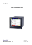
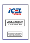
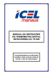
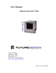
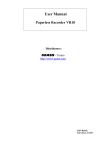
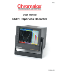
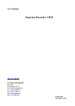
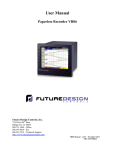
ECR1 Paperless Recorder
Chromalox®
ECR1 Paperless Recorder
The World's First Paperless Recorder of Its Size with So Many Features
For So Many Applications
Process
• Water and Waste
• Electric utilities
• Gas Utilities
• Metals
•
•
•
•
Pharmaceuticals
Chemical
Petrochemical
Food/Beverage/Dairy
• Environmental Monitoring
• Automotive
• Paper and Pulp
Laboratory
OEM
• Environmental Monitoring
• Plastic Extrusion Equipment
• Petrochemical
• Natural Gas
• Food Processing Equipment
• Environmental Chambers
• Furnaces
A Lot of Functionality in a Compact Size
Measuring just 6.5 inches wide by 5.7 inches high and only 6.9 inches deep, what's most
remarkable about the Chromalox® ECR1 paperless recorder is its vivid TFT LCD screen capable
of displaying 256 colors at a true VGA, 640 x 480 pixel resolution.
Plus the Chromalox ECR1 paperless recorder is
packed with so much more:
Panel Mounted Model
• 18 isolated analog input channels
• Easy-to-access function keys
• Plug-and-play I/O card slots
• User-configurable I/O card
• Ethernet or optional RS-232/422/485 communication
• Flash ROM, compact flash card, or PC data storage
• Expandable, modular architecture
• Portable/benchtop option
To prolong the life of the LCD screen, an infrared
detector automatically deactivates the screen when
the operator moves away from it and reactivates it
when the operator approaches within six feet.
Easy Set-Up and Operation
6.1 in. Color TFT LCD,
640 x 480 Pixel Resolution
Infrared Detector
Bench-Top/Portable Model
Soft keys coupled with interactive dialog make setup
easy and operation simple. Data display screens are
easily configured using easy-to-access function keys.
Process data can be displayed in a variety of formats
including vertical and horizontal trends, bar graph,
numerical, or mixed. Statistics can be presented with
instant, average, and minimum/maximum values.
Alarms are programmable and can be displayed in a
message-style format.
Fast, Highly Accurate Sampling Rate
The sampling rate of the Chromalox ECR1 paperless
recorder is fast: within 200 milliseconds for all channels using a programmable filter or moving average
sampling method. With an 18-bit A-D analog input
and 15-bit D-A analog output, the ECR1 is extremely
accurate.
Portable Handle
Power Switch
Compact Flash Card
The World's First Paperless Recorder
2
Rear Terminals
Power Supply
6 Slots for Plug &
Play I/O Cards,
Maximum 18
Analog Input or
Mixed with Analog
and Digital I/O
Cards
Standard Ethernet and Optional
RS232/422/485 Ports
Input and Output Cards
Digital Input
Digital Output (6 Alarms)
Analog Input
Configure Input by
DIP Switches
of Its Size with So Many Features
3
A Variety of Easy-to-Configure, Easy-to-Navigate Displays
Mixed Mode
Bar Graph Mode
• Displays data in bar graph, line trend, and numeric formats
• View a maximum of 6 real-time data values in bar graph format
• View a maximum of 6 mixed, real-time data trends simultaneously
• Scale set by user in "Configuration"
• Different colors and tag names readily identify data trends
• Different colors can be used to display data values and tag names
with each bar graph
• "Page" function key easily switches the view to other
configured pages
• "Hi/Lo" alarm limits can be marked
• Displays current Time/Date
• Displays current Time/Date
• Reminds user of "Alarm" or "Memory Full" conditions
• Reminds user of "Alarm" or "Memory Full" conditions
Trend Mode
Numerical Mode
• View a maximum of 6 real-time data trends vertically
• View a maximum of 6 real-time data points as numbers
• Different colors and tag names readily identify data trends
• Different colors can be used to display data values and tag names
• "Page" function key easily switches view to other configured pages
• "Hi/Lo" alarm limits can be marked
• Displays current Time/Date
• Displays current Time/Date
• Reminds user of "Alarm" or "Memory Full" conditions
• Reminds user of "Alarm" or "Memory Full" conditions
4
Historical Mode
Configuration Mode
• View a maximum of 6 sets of historical data simultaneously
• Configure pen (Input/Output, Pen Name, Event, Job, etc.)
• View desired data sections by using the"Up" and "Down"
function keys
• Configure page (Color, Pen, Decimal, Pen Width, etc.)
• Access precise data values at points selected by moving the "ruler"
• Displays historical data trends and respective data values
• Configure timer
• Configure instrument (Storage Media, Display, Communication,
Time/Date, etc.)
• Trends are readily identified by different colors and individual
tag names
Accessories
Alarm List
Description
Single-Channel Analog Input Card
Part Number
AI181
Dual-Channel Analog Input Card
AI182
Triple-Channel Analog Input Card
AI183
6-Channel Digital Input Card
DI181
6-Channel Relay Output Card (AC/DC)
DO181
RS-2232/422/485 COMM Module
CM181
90-264 Vac, 47-63 Hz Power Supply
PM181
9-18 Vdc Power Supply Module
PM182
18-36 Vdc Power Supply Module
PM183
Portable Handle/Benchtop Assembly Kit
MK183
32 MB Compact Flash Card
CF032
256 MB Compact Flash Card
CF256
Basic PC Software, Observer I
AS181
• Clearly lists all alarm records
Extensive PC Software, Observer II
• Easily browse through an alarm list or "acknowledge" alarms
using function keys
User's Manual
AS182
UMECR1
• Color coded bars remind users of an alarm status
5
Installation
Mechanical Data
Analog Input Card (Al181, Al182, Al183)
6.54 in.
(166mm)
4-wire
RTD
3-wire
RTD
2-wire
RTD
R1
A1
+
5.67 in.
(144mm)
B1
+
TC
7.56 in.
(192mm)
+
mV
V
G1
Analog Output Card (AO181)
7.40 in.
(188mm)
O1+
4-20mA
0-20mA
.79 in.
(20
mm)
Load
R=500 ohms max.
O1
6.85 in.
(174mm)
O1+
6.18 in.
(157mm)
O1
0-5V +
1-5V
0-10V
Load
R=3 K ohms min.
Digital Input Card (Dl181)
5.39 in.
(137mm)
D1+
TTL
D1
Max. .79 in.
(20mm)
Digital Output Card (DO181)
Panel Cutout
Load
A1
5A
240 V
Min. 7.87 in.
(200mm)
B1
AC
or
DC
Wiring Cable
Min.
7.87 in.
(200mm)
Metal Guage
2 max.
4 max.
5.43 in.
(138 +10mm)
5.43 in.
(138 +10 mm)
6
Bare
Length
.4 -.63 in.
(10 -16mm)
+
mA
Specifications
Power
90 to 264 Vac, 47 to 63 Hz, 60 VA, 30 W max
11 to 18 or 18 to 36 Vdc 60 VA, 30 W max
Digital Input Card (DI181)
Channels . . . . . . . . . . . . . . . . . . . . . . . . . . . . . . . . . . . . . . . . . . . . . . . . 6 per card
Logic Low . . . . . . . . . . . . . . . . . . . . . . . . . . . . . . . . . . . . . . . -30 V min, 0.8 V max
Logic High . . . . . . . . . . . . . . . . . . . . . . . . . . . . . . . . . . . . . . . . 2 V min, 30 V max
External Pull-Down Resistance . . . . . . . . . . . . . . . . . . . . . . . . . . . . . . . . . .1 kΩ
External Pull-Up Resistance . . . . . . . . . . . . . . . . . . . . . . . . . . . . . . . . . . . 1.5 MΩ
Display
6.1 in. (155mm) TFT LCD, 640 x 480 pixels, 256 colors
Memory
Storage Memory On Board . . . . . . . . . . . . . . . . . . . . . . . . . . . . . . . . . . . . 8MB
CF Card, Standard . . . . . . . . . . . . . . . . . . . . . . . . . . . . . . . . . . . . . . . . . . . 16MB
CF Card, Optional . . . . . . . . . . . . . . . . . . . . . . . . . . . . . . . . . . .
64MB, 128MB
Analog Input Card (AI181, AI182, AI183)
Resolution . . . . . . . . . . . . . . . . . . . . . . . . . . . . . . . . . . . . . . . . . . . . . . . . . . 18 bits
Sampling Rates . . . . . . . . . . . . . . . . . . . . . . . . . . . . . . . . . . . . . . 5 times/second
Maximum Rating . . . . . . . . . . . . . . . . . . . . . . . . . . . . . . -2 Vdc min, 12 Vdc max
(1 minute for mA input)
Temperature Effect . . . . . . . . . . . . . . . . . . . . . . . . . . . . . ±1.5 µV/ºC for all inputs
(except mA input)
. . . . . . . . . . . . . . . . . . . . . . . . . . . . ±3.0 µV/ºC for mA input
Sensor Lead Resistance Effect
T/C . . . . . . . . . . . . . . . . . . . . . . . . . . . . . . . . . . . . . . . . . . . . . . . . . 0.2 µV/Ω
3-wire RTD . . . . . . . . . . . . . . . 36.7ºF (2.6ºC)/Ω of resistance ∆ of 2 leads
2-wire RTD . . . . . . . . . . . . . . . 36.7ºF (2.6ºC)/Ω of resistance ∑ of 2 leads
Burn-Out Current . . . . . . . . . . . . . . . . . . . . . . . . . . . . . . . . . . . . . . . . . 200 nA
Common Mode Rejection Ratio (CMRR) . . . . . . . . . . . . . . . . . . . . . . . . 120 dB
Normal Mode Rejection Ratio (NMRR) . . . . . . . . . . . . . . . . . . . . . . . . . . 55 db
Isolation Breakdown Voltage Among Channels . . . . . . . . . . . . . . . . 430 Vac min
Sensor Break Detection
TC, RTD, and mV Inputs . . . . . . . . . . . . . . . . . . . . . . . . . . . . Sensor Open
4 to 20 mA Input . . . . . . . . . . . . . . . . . . . . . . . . . . . . . . . . . . . . . . <1 mA
1 to 5 V Input . . . . . . . . . . . . . . . . . . . . . . . . . . . . . . . . . . . . . . . <0.25 V
Other Inputs . . . . . . . . . . . . . . . . . . . . . . . . . . . . . . . . . . . . . . Unavailable
Sensor Break Response Time
TC, RTD, and mV Inputs . . . . . . . . . . . . . . . . . . . . . . . . Within 10 seconds
4 to 20 mA and 1 to 5 V Inputs . . . . . . . . . . . . . . . . . . . . . . . 0.1 seconds
Characteristics
Type
Range
Accuracy
@ 25ºC
Input
Impedence
J
-184º to 1,832ºF
(-120º to 1,000ºC)
±2ºF (±1ºC)
2.2 MΩ
K
-328º to 2,498ºF
(-200º to 1,370ºC)
±2ºF (±1ºC)
2.2 MΩ
T
-418º to 752ºF
(-250º to 400ºC)
±2ºF (±1ºC)
2.2 MΩ
E
-148º to 1,652ºF
(-100º to 900ºC)
±2ºF (±1ºC
2.2 MΩ
B
32º to 3,308ºF
(0º to 1,820ºC)
±4ºF (±2ºC)
2.2 MΩ
R
32º to 3,214ºF
(0º to 1,767.8ºC)
±4ºF (±2ºC)
2.2 MΩ
S
32º to 3,214ºF
(0º to 1,767.8ºC)
±4ºF (±2ºC)
2.2 MΩ
N
-418º to 2,372ºF
(-250º to 1,300ºC)
±2ºF (±1ºC)
2.2 MΩ
L
-328º to 1,652ºF
(-200º to 900ºC)
±2ºF (±1ºC)
2.2 MΩ
PT100
(DIN)
-346º to 1,292ºF
(-210º to 700ºC)
±.7ºF (±0.4ºC)
1.3 MΩ
PT100
(JIS)
-328º to 1,112ºF
(-200º to 600ºC)
±.7ºF (±0.4ºC)
1.3 MΩ
2.2 MΩ
70.5 Ω
mV
-8 to 79 mV
±0.05%
mA
-3 to 27 mA
±0.05%
0~1 V
-0.12 to 1.15 V
±0.05%
32 kΩ
0~5 V
-1.3 to 11.5 V
±0.05%
332 kΩ
1~5 V
-1.3 to 11.5 V
±0.05%
332 kΩ
0~10 V
-1.3 to 11.5 V
±0.05%
332 kΩ
Digital Output Card (DO181)
Channels . . . . . . . . . . . . . . . . . . . . . . . . . . . . . . . . . . . . . . . . . . . . . . . . 6 per card
Contact Form . . . . . . . . . . . . . . . . . . . . . . . . . . . . . . . . . . . . . . . . . . N.O. (Form A)
Relay Rating . . . . . . . . . . . . . . 5 A/240 Vac, 200,00 Life Cycles for Resistive Load
COMM Module (CM181)
Interface . . . . . . . . . . . . . . . . . . . . . . . . . . . . . . . . . . . . RS-232 (1Unit) RS-485 or
. . . . . . . . . . . . . . . . . . . . . . . . . . . . . . . . . RS-422 (Up to 247 Units)
Protocol . . . . . . . . . . . . . . . . . . . . . . . . . . . . . . . . . MODBUS Protocol RTU Mode
Address . . . . . . . . . . . . . . . . . . . . . . . . . . . . . . . . . . . . . . . . . . . . . . . . . . .1 to 247
Baud Bits . . . . . . . . . . . . . . . . . . . . . . . . . . . . . . . . . . . . . . . . . 0,3 to 38.4kB/sec
Data Bits . . . . . . . . . . . . . . . . . . . . . . . . . . . . . . . . . . . . . . . . . . . . . . . . 7 or 8 Bits
Parity Bit . . . . . . . . . . . . . . . . . . . . . . . . . . . . . . . . . . . . . . . . None, Even, or Odd
Stop Bit . . . . . . . . . . . . . . . . . . . . . . . . . . . . . . . . . . . . . . . . . . . . . . . . . 1 or 2 Bits
Standard Ethernet Communication
Protocol . . . . . . . . . . . . . . . . . . . . . . . . . . . . . . . . . . . . MODBUS TCP/IP, 10BaseT
. . . . . . . . . . . . . . . . . . . . . . . . . . . . . Auto Polarity Correction for 10BaseT
Ports . . . . . . . . . . . . . . . . . . . . . . . . . . . . . . . . . AUI (Attachment Unit Interface) and
. . . . . . . . . . . . . . . . . . . . . . . . . . . . . . . . . . . . . . RJ-45 Auto-Detect Capability
Infrared Detector
Distance . . . . . . . . . . . . . . . . . . . . . . . . . . . . . . . . . Detects Movement within 2 m
Environmental & Physical
Operating Temperatures . . . . . . . . . . . . . . . . . . . . . . . . 41º to 122ºF (5º to 50ºC)
Storage Temperatures . . . . . . . . . . . . . . . . . . . . . . . . 13º to 140º (-25º to 60ºC)
Humidity . . . . . . . . . . . . . . . . . . . . . . . . . . . . . 20% to 80% RH (Non-Condensing)
Insulation Resistance . . . . . . . . . . . . . . . . . . . . . . . . . . . . 20 MΩ min @ 500 Vdc
Dielectric Strength . . . . . . . . . . . . . . . . . . . . . . . 3,000 Vac 50/60 Hz for 1 minute
Vibration Resistance . . . . . . . . . . . . . . . . . . . . . . . . 10 to 55 Hz, 10 m/S2 for 2 hr
Shock Resistance . . . . . . . . . . . . . . . . . . . . . . . . . . . 30 m/S2 (3g) for Operation,
. . . . . . . . . . . . . . . . . . . . . . . . . . . . . . 100g for Transportation
Dimensions . . . . . . . 6.5 in./166mm (W) X 5.7 in./144mm (H) x 6.9 in./175mm (D)
Approval Standards
Safety . . . . . . . . . . . . . . . . . . . . . . . . . . . . . . . . . . . . UL 873 (11th Edition, 1994)
. . . . . . . . . . . . . . . . . . . . . . . . . . . . . . . . . . . . . . . . CSA C22.2 No. 24 to 93
. . . . . . . . . . . . . . . . . . . . . . . . . . . . . . . . . . . . . . . . CE EN610-1 (lEC1010-1)
. . . . . . . . . . . . . . . . . . . . . . . . . Overvoltage Category II, Pollution Degree 2
Protective Class . . . . . . . . . . . . . . . . . . . . . . . . . . . IP 30, Front Panel Indoor Use
IP 20, Housing and Terminals
EMC . . . . . . . . . . . . . . . . . . Emission: EN50081-1, EN61326, EN55011 Class B,
EN61000-3-2, EN61000-3-3
. . . . . . . . . . . . . . . . . . Immunity: EN50082-2, EN61326, EN61000-4-2,
EN61000-4-3, EN61000-4-4, EN61000-4-5
EN61000-4-6, EN61000-4-11, EN50204
7
Ordering Information
Model
ECR1
Paperless Recorder
Code
4
6
7
Power
90-264 Vac. 47-63 Hz
11-18 Vdc
18-36 Vdc
Code
3
6
A
B
C
D
Analog Input Card
3 Channels (1 Card*)
6 Channels (2 Cards*)
9 Channels (3 Cards*)
12 Channels (4 Cards*)
15 Channels (5 Cards*)
18 Channels (6 Cards*)
Code
0
1
2
Digital Input Card
None
6 Channels (1 Card*)
12 Channels (2 Cards*)
Code
0
1
2
Digital Output Card
None
6 Relays (1 Card*)
12 Relays (2 Cards*)
Code
0
1
2
Communications
Standard Ethernet Interface
RS-232/422/485 (Three in One) + Ethernet Interface
Special Order
Code
1
2
PC Software
Free Basic Software, Observer I for Non-Communication Application
Extensive Software, Observer II for Communication via
RS232/422/485 or Ethernet
Code
0
1
Firmware
Basic Function
With Mathematics, Counter, and Totalizer
Code
1
4
Storage Media
32MB Compact Flash (CF) Card
256MB CF Card
Code
1
2
Case/Mounting
Standard Panel Mounting
Bench-Top/Portable with Handle
Code
0
1
2
3
4
5
6
ECR1 - 4
A
0
0
-
0
1
0
-
1
1
Special Option
None
24 Vdc Auxiliary Power Supply
(for Transmitter, 6 Channels)
3-Channel Analog Output
6-Channel Analog Output
8-Channel Analog Output
Panel Mounting with Power Plug
Panel Mounting with Power Switch
0
Typical Model Number
* Standard model without options, ECR1-4A00010110.
* The rear slots of the recorder will accept only up to 6 cards in any combination.
Chromalox
®
PRECISION HEAT AND CONTROL
103 Gamma Drive
Pittsburgh, PA 15238
USA
Chromalox - UK
Eltron House
20-28 Whitehorse Road
Croydon, Surrey, CR9 2NA, UK
Chromalox - France
Route de Château-Thierry
Noyant et Aconin
F-02203 SOISSONS Cedex, France
Toll-Free: 1-800-443-2640
Tel: +44 (0)20 8665 8900
Fax: +44 (0)20 8689 0571
Tel: +33 (0)3 23 74 39 39
Fax: +33 (0)3 23 74 39 00
email: [email protected]
www.chromalox.com
email: [email protected]
www.chromalox.co.uk
email: [email protected]
www.chromalox.fr
Phone: (412) 967-3800
Fax: (412) 967-5148
© 2006 Chromalox, Inc. All Rights Reserved.
PDS ECR1
1/06