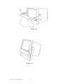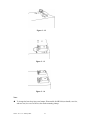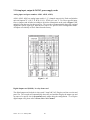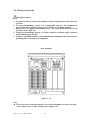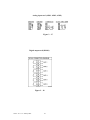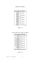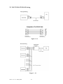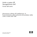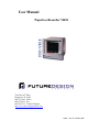
1
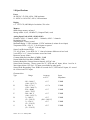
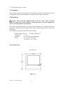
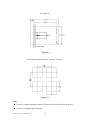
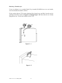
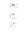
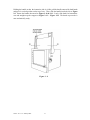
User Manual
Paperless Recorder VR18
7524 West 98th Place
Bridgeview, IL 60455
888.751.5444 - Office:
888.307.8014 - Fax
866.342.5332 - Technical Support
http://www.futuredesigncontrols.com/
VR18 – v2.0 - 1L: January 2005
Page
Contents
Safety --------------------------------------------------------------------------------Safety Symbols -------------------------------------------------------------------------Safety Notes and Precautions ---------------------------------------------------------Static Electricity -----------------------------------------------------------------------
1. General Description -------------------------------------------------------------------1.1
1.2
1.3
1.4
1.5
1.6
1.7
1.8
Unique Features of Recorder ------------------------------------------------------Expandable Input and Output cards -----------------------------------------------Communication -----------------------------------------------------------------------Storage Media CF card ----------------------------------------------------------------Data Security -------------------------------------------------------------------------Infrared Detector --------------------------------------------------------------------Ordering Codes and Accessories -------------------------------------------------Specifications -------------------------------------------------------------------------
2. Installation and wiring ----------------------------------------------------------------2.1
2.2
2.3
2.4
2.5
2.6
Unpacking -------------------------------------------------------------------------------Installation -------------------------------------------------------------------------------Setup Input, Output & 24VDC power supply cards -----------------------------Wiring for the cards -------------------------------------------------------------RS-232, RS-422, RS-485 wiring --------------------------------------------------Installation of Compact Flash CF Card -----------------------------------------------
3. Basic Operation --------------------------------------------------------------------------3.1
3.2
3.3
3.4
3.5
3.6
3.7
3.8
3.9
3.10
3.11
Page ------------------------------------------------------------------------------Mode -----------------------------------------------------------------------------History ------------------------------------------------------------------------------Event ----------------------------------------------------------------------------Status ------------------------------------------------------------------------------Exit --------------------------------------------------------------------------------Dump -----------------------------------------------------------------------------Clear ------------------------------------------------------------------------------Operate ---------------------------------------------------------------------------Shutdown ------------------------------------------------------------------------Small Icons ------------------------------------------------------------------------
4. Configuration -------------------------------------------------------------------4.1
4.2
4.3
4.4
4.5
Channel -------------------------------------------------------------------------------Display --------------------------------------------------------------------------Tools ( Timer, Counter & Totalizer ) ------------------------------------------------Instrument ------------------------------------------------------------------------Clock ---------------------------------------------------------------------------------------
VR18 - v2.0 - 1L: January 2005
2
4
4
4
5
6
6
6
6
7
7
7
8
10
13
13
13
20
22
25
26
27
27
28
28
29
30
30
31
31
31
31
32
33
34
37
39
43
45
4.6 System Info ----------------------------------------------------------------------4.7 Demo ------------------------------------------------------------------------------------4.8 A Configuration Example -------------------------------------------------------------
46
47
47
5. PC Software – Observer I & II -----------------------------------------------------
48
48
48
48
48
49
50
5.1
5.2
5.3
5.4
5.5
5.6
Hardware Requirements --------------------------------------------------------Set-Up ------------------------------------------------------------------------------PC Software Manual – HELP ----------------------------------------------------Observer I – The basic software for non-communication application -------Observer II – The extensive software for communication application ----How to use PC Software ----------------------------------------------------------------
6. Mathematics -------------------------------------------------------------------------------6.1 Math Expressions and an example ----------------------------------------------------
VR18 - v2.0 - 1L: January 2005
3
52
52
Safety
This recorder is compliant with the requirements of EN61010-1, UL 61010C-1 & CSA C22.2
No. 1010.1-92. The protection provided by the recorder may be impaired if it is used in a
manner inconsistent with its intended purpose, or in an environment that exceeds the
specifications of the recorder. Future Design Controls, Inc. is not liable for customer’s failure
to comply with these requirements.
Safety Symbols
The following symbols may be seen on the recorder labeling.
Protective Earth
DC Supply
Safety Notes and Precautions
1. The protective earth terminal should be connected first before any other connection is made.
To avoid making the recorder dangerous under fault conditions, any interruption of the
protective Earth conductor inside or outside the recorder is prohibited. Even in the case of a
portable unit, the protective earth terminal must remain connected if the recorder is
connected to any hazardous voltage.
2. Keep signal and supply voltage wiring separated from one another. If this is impractical, use
shielded cables for signal wiring. Double insulation should be used for signal wiring when
the recorder is being used with hazardous voltage.
3. Do not use the recorder where there is high vibration, or high magnetic field, this could cause
damage or error of measurement.
4. All maintenance or repairs should be carried out with power disconnected, to avoid personal
injury, or damage to the unit.
5. In areas with conductive pollution, adequate ventilation, filtering and sealing need to be
installed.
VR18 - v2.0 - 1L: January 2005
4
6. When cleaning the recorder, handle carefully and use soft dry cloth. Avoid the use of
abrasives or any sharp and hard objects which would damage the display.
7. Do not operate the recorder if any part has been removed or disassembled. Consult your
nearest dealer at once.
Static Electricity
Appropriate precautions must be taken when handling the recorder. The circuit board,
components are susceptible to damage caused by electrostatic discharge. Take static electricity
precautions whilst handling and inserting Compact Flash Card into the recorder.
To replace the power-line fuse
The power-line fuse is located within the fuse-holder on the power board. For 90-250 VAD
line voltages, the user must use a 2.5A time-lag fuse, and for both 11-18 VDC and 18-36 VDC
line voltages, a 5.0A time-lag fuse must be used.
VR18 - v2.0 - 1L: January 2005
5
1. General Description
1.1 Unique features of recorder
The VR18 is a well-designed paperless recorder with many outstanding features including:
• 6.1〞TFT Color LCD with VGA Display in 640x480 pixels.
• 18 isolated Analog Inputs
• Plug & play I/O cards for easy expansion
• Simple and friendly operation
• Infrared detector to prolong lifetime of LCD
• Solid storage media CF card in high capacity
• 174 mm short depth
• Ethernet as standard and optional RS-232/422/485 communication
• High accuracy 18-bit A-D Analog Input
• 15-bit D-A Analog Output.
• 200 milli second sample rate.
• Bench top with convenient portable handle, easy converted into panel mount
1.2 Expandable Input and Output Cards
The recorder is equipped with six-rear expansion slots, which work flexibly with the following
plug & play I/O cards.
Analog Input cards (part number AI181, AI182, AI183): These three cards are used for 1, 2,
& 3-channel analog input. Each input is isolated from each other to avoid noise and to ensure
stable measurement. Analog input is configured by DIP switches and jumpers on the card
before plugging into rear expansion slot. Refer 2.3 Setting Input and Output Cards.
Digital Output card (DO181): Each card includes 6 alarm relays. Contacts are rated 5
Amp/240 VAC
Digital Input card (DI181): Each card includes 6 channels. Logic Low: -5V minimum, 0.8V
maximum, Logic High: -2V minimum, 5V maximum
1.3 Communication
The standard communication interface is Ethernet with protocol IEEE 802.3 - 10 Base T. Other
options are RS-232 / RS-422 / RS-485.
VR18 - v2.0 - 1L: January 2005
6
1.4 Storage Media CF Card
The Solid Compact Flash Memory Card (CF Card ) 16 MB capacity is a free standard storage
media used for this instrument. Its compact size, anti-dust and anti-vibration features increase
its reliability. To read measured data on CF Card, add a CF reader on USB port of PC. Higher
capacity 64 and 128MB CF Cards are upon request. Alternatively the user may purchase locally.
To ensure compatibility, we recommended only two brands SanDisk and Transcend.
To read the configuration and measured data on CF card for the first time, it is necessary to
press Save key to save configuration, and then press Dump key to Dump measured data from
the recorder to the CF card before inserting it into the CF card reader. If configuration have
been changed, press both keys before insert CF card into reader. If configuration remains
unchanged, press Dump key only.
Each record of data uses 2 bytes of CF card memory.. If the Log Speed ( the recording speed of
measured data ) is set to the fastest speed at 1 second per data, then for a single channel, 16
MB CF card will last approximately 92 days [= 16 MB / ( 2 bytes x 24 hours x 60 minutes x
60 seconds)].
The following formula is to calculate how many days the CF card could do saving before it is
full.
The ? days = The capacity of CF Card / ( 2 bytes / the Log Speed x the working hours per
day x 3600 seconds )
To avoid loosing recorded data while storing on PC, it is necessary to insert CF card back
again into the recorder soon after loading recorded data onto PC.
1.5 Data Security
The recorded data is stored in the manufacturer’s special binary format. It is not possible to
manipulate or modify those recorded data. This feature fully guarantees the security of the
data.
1.6 Infrared Detector (IR Detector)
The use of Passive Infrared technology on the recorder is an innovative idea to prolong the
lifetime of the LCD display. The detector senses the movement of body heat from a distance of
approximately 2 meters. This feature works together with the Screensaver. For example, if the
IR Sensor is turned on and Screensaver set to 10 Min, then the display will turn off 10 minutes
after the user walks away from the recorder. The Passive Infra Red detects when the user
returns to the recorder and the display turns on straight away, no need to press any key on the
recorder. If the user does not prefer using this function, it can be disabled.
VR18 - v2.0 - 1L: January 2005
7
1.7 Ordering codes and accessories
Ordering codes
VR18 – □□□□ – □□□ – □□□
1 2 3 4 – 5 6 7 – 8 9 10
1
Power
4: 90-250 VAC, 47-63 Hz
6: 11-18 VDC
7: 18-36 VDC
9: Special order
2
Analog Input Card
0: none
1: 1 channel
2: 2 channel
3: 3 channel
4: 4 channel
5: 5 channel
6: 6 channel
A: 9 channel
B: 12 channel
C: 15 channel
D: 18 channel
3
Digital Input Card
0: none
1: 6 channel
2: 12 channel
4
Digital Output Card
0: none
1: 6 relay
2: 12 relay
5
Communication
0: standard Ethernet interface
1: RS-232/422/485 ( three in one ) + Ethernet interface
9: Special order
6
PC software
1: Free basic software Observer I for non-communication application
2: Extensive software Observer II for communication of RS-232/422/485 or Ethernet
7
Firmware
0: Basic function
1: with Mathematics, Counter & Totalizer
VR18 - v2.0 - 1L: January 2005
8
8
Storage Media
1: 16MB Compact Flash card ( CF )
3: 128 MB CF card
X: other options
9
Case/Mounting
1: standard Panel Mounting
2: Bench top / Portable style with handle
10 Special Option:
0: none
1: 24VDC auxiliary power supply ( for transmitter, 6 channels )
2: 3-channel analog output
3: 6-channel analog output
4: 9-channel analog output
X: other options
Accessories:
Part no.
Description
AI181, AI182, AI183
1, 2, 3-channel analog input card (TC, RTD, mA, voltage )
AI181V, AI182V, AI183V 1, 2, 3-channel voltage input card (+, - voltage only)
DI181
6-channel digital input card
DO181
6-channel relay output card ( AC/DC )
CM181
RS-232/422/485 + Ethernet COMM module
CM182
Standard Ethernet COMM module
PM181
90-250 VAC, 47-63 Hz power supply
PM182
11-18 VDC power supply module
PM183
18-36 VDC power supply module
AP181
24 VDC auxiliary power supply card for 6 transmitters
MK183
bench top / portable handle assembly kit
CF016
16MB compact flash card
CF064
64MB compact flash card
CF128
128MB compact flash card
AS181
Basic PC software Observer I
AS182
Extensive PC software Observer II
UMVR181 User’s Manual
BT181
Boot ROM without Math, Counter & Totalizer
BT182
Boot ROM with Math, Counter & Totalizer
SC181
Slot cover for vacant slot
SNA10A
RS-485 to RS-232 converter
AO183
3-channel analog output card
Notes:
The rear Slots of the recorder will only accept up to 6 optional cards of input, output or 24
VDC power supply. For example, 12-channel analog input needs 4 pcs. of 3-channel
analog input card AI183. Now it is left 2 empty Slots for other cards.
The basic PC software Observer I is supplied free together with recorder. There is an
additional charge for the extensive PC software Observer II supplied with communication
of RS-232/422/485 or Ethernet.
VR18 - v2.0 - 1L: January 2005
9
1.8 Specifications
Power
90-250VAC, 47-63Hz, 60VA, 30W maximum
11-18VDC or 18-36 VDC, 60VA, 30W maximum
Display
6.1〞TFT LCD, 640X480 pixel resolution, 256 colors
Memory
8MB storage memory on board
Storage media: 16, 64, 128 MB CF ( Compact Flash ) cards
Analog Input Card (AI181, AI182, AI183)
Channels: AI181 ~ 1 channel, AI182 ~ 2 channels, AI183 ~ 3 channels
Resolution: 18 bits
Sampling Rate: 5 times/ second
Maximum Rating: -2 VDC minimum, 12 VDC maximum (1 minute for mA input)
Temperature Effect: ±1.5 µV/ ˚C for all inputs except mA
±3.0 µV/ ˚C for mA input
Sensor Lead Resistance Effect:
T/C: 0.2 µV/ohm 3-wire RTD: 2.6 ˚C /ohm of resistance difference of two leads
2-wire RTD: 2.6 ˚C /ohm of resistance sum of two leads
Burn-out Current: 200nA
Common Mode Rejection Ratio (CMRR): 120dB
Normal Mode Rejection Ratio (NMRR): 55dB
Isolation Breakdown Voltage between channels: 430VAC min.
Sensor Break Detection: Sensor opened for TC, RTD and mV inputs, below 1 mA for 420mA input, below 0.25V for 1-5V inputs, unavailable for other inputs
Sensor Break Responding Time: Within 10 seconds for TC, RTD and mV inputs, 0.1 second
for 4-20 mA and 1-5V inputs
Characteristics:
Type
J
K
T
E
B
R
S
Range
Accuracy
at 25 ˚C
-120 ~ 1000 ˚C
(-184 ~ 1832 ˚F)
-200 ~ 1370 ˚C
(-328 ~ 2498 ˚F)
-250 ~ 400°˚C
(-418 ~ 752˚F)
-100 ~ 900 ˚C
(-148 ~ 1652 ˚F)
0 ~ 1820 ˚C
(32 ~ 3308 ˚F)
0 ~ 1768 ˚C
(32 ~ 3214 ˚F)
0 ~ 1768 ˚C
(32 ~ 3214 ˚F)
±1 ˚C
2.2MΩ
±1 ˚C °
2.2MΩ
±1 ˚C
2.2MΩ
±1 ˚C
2.2MΩ
±2 ˚C
(200 ~ 1820 ˚C)
±2 ˚C
2.2MΩ
±2 ˚C
2.2MΩ
VR18 - v2.0 - 1L: January 2005
10
Input
Impedance
2.2MΩ
N
L
PT100
(DIN)
PT100
(JIS)
mV
mA
0~1V
0~5V
1~5V
0~10V
-250 ~ 1300 ˚C
(-418 ~ 2372 ˚F)
-200 ~ 900 ˚C
(-328 ~ 1652 ˚F)
-210 ~ 700 ˚C
(-346 ~ 1292 ˚F)
-200 ~ 600 ˚C
(-328 ~ 1112 ˚F)
-8 ~ 70mV
-3 ~ 27mA
-0.12 ~ 1.15V
-1.3 ~ 11.5V
-1.3 ~ 11.5V
-1.3 ~ 11.5V
±1 ˚C
2.2MΩ
±1 ˚C
2.2MΩ
±0.4 ˚C
1.3KΩ
±0.4 ˚C
1.3KΩ
±0.05%
±0.05%
±0.05%
±0.05%
±0.05%
±0.05%
2.2MΩ
70.5Ω
332KΩ
332KΩ
332KΩ
332KΩ
Digital Input Card (DI181)
Channels: 6 per card
Logic Low: -30V minimum, 0.8V maximum
Logic High: 2V minimum, 30V maximum
External pull-down Resistance: 1KΩ maximum
External pull-up Resistance: 1.5MΩ minimum
Digital Output Card (DO181)
Channels: 6 per card
Contact Form: N.O. (form A)
Relay Rating: 5A/240 VAC, life cycles 200,000 for resistive load
24VDC Auxiliary Power Supply Card ( AP181)
Channels: to be used for 6 transmitters
Output Rating: 24 ± 1 VDC, 180mA in maximum, 30mA / each channel
COMM Module (CM181)
Interface: RS-232 (1 unit), RS-485 or RS-422 (up to 247 units)
Protocol: Modbus Protocol RTU mode
Address: 1-247
Baud Rate: 0.3~38.4 Kbits/sec.
Measured data Bits: 7 or 8 bits
Parity Bit: None, Even or Odd
Stop Bit: 1 or 2 bits
Standard Ethernet Communication
Protocol: Modbus TCP/IP, 10 Base T
Ports: AUI (Attachment Unit Interface) and RJ-45, Auto- detect capability
VR18 - v2.0 - 1L: January 2005
11
Infrared Detector
Distance: Detect moving human body in distance around 2 meters
Time delayed: 10, 20, 30, 40, 50 or 60 minutes to be defined
Environmental & Physical
Operating Temperature: 5 ~ 50 ˚C
Storage Temperature: -25 ~ 60 ˚C
Humidity: 20 to 80% RH (non-condensing), maximum relative humidity 80% for temperature
up to 31˚C decreasing linearly to 50% relative humidity at 40˚C
Altitude: 2000 M maximum
Insulation Resistance: 20 M ohms min. (at 500 VDC)
Dielectric Strength: 3000 VAC, 50/60 Hz for 1 minute
Vibration Resistance: 10-55 Hz, 10m/ s² for 2 hours
Shock Resistance: 30m/ s² (3g) for operation, 100g for transportation
Operation Position: no inclined restriction
Dimensions: Panel Mount style: 166(W) x 144(H) x 174mm(D)
Bench Top style: 166 (W) x 192 (H) x 194mm (D)
Standard Panel Cutout: DIN size in 138 x 138mm
Approval Standards
Safety: UL61010C-1, CSA C22.2 No. 1010.1-92
EN61010-1 (IEC1010-1) over voltage category II, Pollution degree 2
Protective Class:
IP 30 front panel for indoor use,
IP 20 housing and terminals
EMC:
Emission: EN50081-1, EN61326
(EN55011 class B, EN61000-3-2, EN61000-3-3)
Immunity: EN50082-2, EN61326 (EN61000-4-2, EN61000-4-3,
EN61000-4-4, EN61000-4-5, EN61000-4-6,
EN61000-4-11, EN50204)
VR18 - v2.0 - 1L: January 2005
12
2. Installation and wiring
2.1 Unpacking
If any damage is found while unpacking, the user should contact the local representative at once.
It is suggested that the special packaging is retained for possible future requirement.
2.2 Installation
Remove stains from this equipment using a soft, dry cloth. Don’t use harsh
chemicals, volatile solvent such as thinner or strong detergents to clean the equipment in
order to avoid deformation or decoloration.
The recorder is designed for indoor use and not in any hazardous area. It should be kept away
from shock, vibration, and electromagnetic fields such as variable frequency drives, motors and
transformers.
It is intended to be operated in the following environment:
Pollution Degree Level II
IEC1010-1(EN61010-1)
Temperature
5 ~ 50 ˚C
Humidity
20 ~ 80 % RH (non-condensing)
Power
90 ~ 250 VAC, 50/60 Hz
11-18 VDC or 18 - 36 VDC
Panel mounting style
The front side
Figure 2 - 1
VR18 - v2.0 - 1L: January 2005
13
The right side
Figure 2 - 2
Panel Cutout (standard DIN size 138 mm x 138 mm)
Figure 2 - 3
Note:
Do not over tighten mounting clamp screws that could result in distortion of the case.
There is no mounting angle restriction.
VR18 - v2.0 - 1L: January 2005
14
Bench top / Portable style
For use on desktop or as a portable Bench Top Assembly Kit MK184 (two ears, one handle,
two feet included).Assemble as follows:
Firstly, put the right ear FV-R on the right hand side of metal case, and slide it into the case by
pushing in direction as shown in Figures 2-4 through Figure 2-8. Ensure that the ear is firmly
plugged into case. Do the same with the left ear FV-L.
Figure 2 - 4
Figure 2 - 5
VR18 - v2.0 - 1L: January 2005
15
Figure 2 - 6
Figure 2 - 7
Figure 2 - 8
VR18 - v2.0 - 1L: January 2005
16
Holding the handle so that the instruction side is visible, pull the handle outward by both hands
and put it in vertical position on the top of case. Then, slide the handle into both ears as Figure
2-9. Rotate the handle downward as Figure 2-10 & 2-11. Lastly, slide both feet beneath the
case and straighten up the stoppers as Figure 2-12 ~ Figure 2-14. The bench top recorder is
now mechanically ready.
Figure 2 - 9
VR18 - v2.0 - 1L: January 2005
17
Figure 2 - 10
Figure 2 - 11
VR18 - v2.0 - 1L: January 2005
18
Figure 2 – 12
Figure 2 – 13
Figure 2 – 14
Note:
To change the bench top into panel mount. Disassemble kit MK184 (one handle, two feet,
and two ears) in reverse of above, then fit the mounting clamps.
VR18 - v2.0 - 1L: January 2005
19
2.3 Setup input, output & 24VDC power supply cards
Analog input card (part numbers AI181, AI182, AI183)
AI181, AI182, AI183 are analog input cards in 1, 2, 3 channels respectively. Each card includes
universal input of TC (J, K, T, E, B, R, S, N, L), PT100, mV, mA, V. To select a specific input,
first set jumpers and switches according to the sticker information on the card as Figure 2–15,
and plug it into the rear slot then power on. The recorder will automatically detect the card and
display the specific input type, then show its source of a specific slot in Configuration Mode.
All inputs were initially set for 4-20mA from the factory.
Figure 2 – 15
Digital Output card (DO181) / 6 relay alarm card
The digital output card includes 6 relays rated 5 Amp/240 VAC. Plug the card into rear slot and
power on. The recorder will automatically detect the card and then display the output type and
its source of a specific slot in System Info mode whilst doing the configuration. To set up the
digital output card, please refer to Event, Job of 4.1 Channel.
VR18 - v2.0 - 1L: January 2005
20
Digital Input card (DI181)
This card includes 6 channels of event 1, 2, 3, 4, 5 & 6. As above, plug the card into rear slot
and power on. The recorder will automatically detect it, and then display the input type and its
source of a specific slot in System Info mode whilst doing the configuration.
24 VDC auxiliary power supply card (AP181)
This card can supply the power to 6 transmitters. The output rating is 24 ± 1 VDC, 180 mA in
maximum, 30mA / each transmitter.
VR18 - v2.0 - 1L: January 2005
21
2.4 Wiring for the cards
Wiring Precautions
1. Care must be taken to ensure that maximum voltage rating specified on the label is not
exceeded.
2. For the panel-mounting version, it is recommended that near the equipment an
external fuse and an external switch rated at 2A/250 VAC should be equipped.
3. Beware not to over tighten the terminals screws. The torque should not exceed 1 N-m
(8.9 Lb-in or 10.2 Kg F-cm).
4. Except the thermocouple wirings, all wirings should be stranded copper conductor
with maximum gauge 18 AWG.
5. Connect a grounding conductor with 1.6mm diameter minimum to provide protective
grounding prior to turning on the equipment.
Rear terminals
Figure 2 – 16
Note:
▲ The six rear Slots can be inserted only by six cards in maximum. It can be any input
card, output card or 24 VDC auxiliary power supply card.
VR18 - v2.0 - 1L: January 2005
22
Analog input card (AI181, AI182, AI183)
Figure 2 – 17
Digital output card (DO181)
Figure 2 – 18
VR18 - v2.0 - 1L: January 2005
23
Digital input card (DI181)
Figure 2 – 19
24 VDC auxiliary power supply card (AP181)
Figure 2 – 20
VR18 - v2.0 - 1L: January 2005
24
2.5 RS-232, RS-422, RS-485 wiring
Figure 2 – 21
Figure 2 – 22
VR18 - v2.0 - 1L: January 2005
25
Figure 2 – 23
2.6 Installation of Compact Flash CF card
A 16MB Compact Flash Card is installed in each VR18. If a bigger capacity Compact Flash
card is required, and the user decides to buy it locally, please check the brand name of CF card.
To be compatible, it should be one of two recommended brands SanDisk or Transcend. Other
brands are not compatible therefore not recommended.
Installation: First insert Compact Flash card to the end, then turn the stopper to the right.
Pulling out: First turn the stopper to the straight direction, then pull out the CF card.
Note:
To read measured data and events on CF card, it is necessary to install software Observer I
or II on PC first. Then, connect a CF reader to USB port of PC. Finally, insert CF card
into the reader.
The power should be turned off while inserting input and output cards.
recommended to insert input or output cards while the unit is switched on.
VR18 - v2.0 - 1L: January 2005
26
It is not
3. Basic Operation
After installation and wiring, power on the recorder, six soft keys Page, Mode, History, Event,
Status and Exit will appear on the left hand side of LCD display. Opening the plastic cover at
the front of the recorder, the user may find another five soft keys Dump, Clear, Operate, Config
and Shutdown. These eleven soft keys are used for operation. On the top right side, small
icons of buzzer, evnt, mem, CF and Date/Time display.
Figure 3 – 1
Soft keys:
3.1 Page
Page means the display. The recorder can have a maximum of 6 Pages and each Page can
display a maximum of 6 channels. A channel can display either measured data or computed
measured data. If channels cover more than one page, press the Page key, to move forward
from Page 1 to Page 2…
VR18 - v2.0 - 1L: January 2005
27
3.2 Mode
Mode defines the type of display. Options are Mix, Trend, Bar or Digital mode.
Mix: The display default is Mix mode. Several modes can be mixed together including
horizontal/ vertical trend, bar and digital modes.
Trend: Press Mode key, to display Trend mode. This is measured data trend in real time. The
same page/display may have a maximum of 6 trends in different colors. The user may define
each color, details in 4.2 Display.
Bar: Press Mode key again, to display bars in different colors. The scale of each bar can be
defined individually, details in 4.2 Display.
Digital: Press Mode key again, to display digits in different colors. Press Mode key again, to
return to the original Mix mode.
3.3 History
Press History key, to display historical trend. Press directional keys ← → to move backward
or forward. Press Zoom key to zoom in the time scale. It may be zoomed in for 9 minutes, 1
hour, 12 hours, one day or one week. Press Back key to return to the original display.
VR18 - v2.0 - 1L: January 2005
28
3.4 Event
Press Event key, the Event /Alarm List displays general Events, Alarms and Reports. Press
Mode key to choose Evnt/Alam ( Event/Alarm ) or Report.
Event/Alarm
It displays the Ack (acknowledgement), Type, Source, Active time, Clear time and Value of
events or alarms. Use directional keys ↓ ↑ to move downward or upward. Press Ack All key to
acknowledge the alarm. Events do not need to be acknowledged. Press Back key to return to
the original display.
Figure 3 – 2
On the Event / Alarm List, three different colors indicate the status of the alarm.
Red - Presently in alarm status.
Green – The cause of alarm status was temporary, and has now returned to normal.
Grey – A temporary alarm (in green status), after having been acknowledged, then
becomes grey.
Active Time is the time that alarm status becomes active. Clear Time is the time when two
conditions are met. Firstly alarm status is cleared and becomes normal, and secondly the user
has acknowledged it. Once an alarm occurs, the red buzzer icon on the top right starts flashing.
After the cause of alarm is no longer met and the alarm is acknowledged, then the red buzzer
icon disappears. When Clear Time shows Terminated this indicates that the alarm has been
terminated by turning off the power.
VR18 - v2.0 - 1L: January 2005
29
Report
Press Mode key to choose Report, after the option of Math. Counter & Totalizer has been
selected. This produces reports about Counter and Totalizer. Press Report key to select the
report in daily, weekly or monthly base. Press directional keys ← → to choose the exact day,
week or month.
Figure 3 – 3
3.5 Status
Press Status key, the Status List displays present status of digital input DI, digital output DO
(alarm relay), Counter and Totalizer. Press Mode key to choose any mode of DI, DO, Counter
or Totalizer. Display shows the status DI, DO, Counter or Totalizer at the present time.
3.6 Exit
Press Exit key to close existing operation, the soft keys on the left hand side disappear giving
full display. Press any soft key on the left hand side, these six soft keys Page, Mode, History,
Event, Status and Exit appear again. Open the plastic cover at the front low side then another
five soft keys Dump, Clear, Operate, Config & Shutdown appear.
VR18 - v2.0 - 1L: January 2005
30
3.7 Dump
Before removing the CF card from the recorder, it is necessary to press the Dump key to
transfer the measured data and events from the internal memory of the recorder to the CF card
3.8 Clear
When the internal memory is down to 25%, the mem icon on the top right changes color from
green to red. Also, when the internal memory reserved for events is down to 25 %, the evnt
(event) icon on the top right changes color from green to red. In each case the user should
transfer all the measured data from the recorder to CF card by pressing Dump key as above.
However, if the measured data and events are not significant information, the user may also
press Clear key to clear them.
3.9 Operate
Press Operate key to start a job manually. For example: to record the alarm by selecting Log
alarm. There are various jobs that may be assigned, as described in Event, Job of 4.1
Channel.
Details about soft key Config are described in 4. Configuration.
3.10 Shutdown
Accidental turning off the power will cause loss of data and will interrupt the operation of the
recorder. Therefore press the Shutdown key to shutdown the system first before turning off the
power.
VR18 - v2.0 - 1L: January 2005
31
3.11 Small icons (on the top right side ):
Figure 3 – 4
Buzzer: Appears by flashing in red whenever the alarm status occurs. The buzzer will
disappear after the user acknowledges the alarm, or the process becomes normal.
Evnt: The percentage of memory space left for events/alarms. For example, evnt 84% means
84% space left for events/alarms. Refer to Event/Alarm Limit in 4.4 Instrument. Various
numbers of events/alarms can be set. The icon flashes red when memory space is down to 25 %.
The icon returns to normal green after pressing the soft key, either Dump or Clear.
mem: The percentage of memory space left for measured data. The icon starts flashing red
when the memory space is down to 25%. The icon becomes normal green after press soft key
either Dump or Clear. If the internal memory goes down to 10 %, the earliest measured data
and events will be saved to CF card in small batch automatically. If there is no CF card
inserted, then the earliest measured data and events will be overwritten and replaced by the
latest measured data and events.
CF: The icon shows the status of Compact Flash card. If the CF card is not inserted, the icon
shows a red-cross sign. If it is properly inserted, then the icon displays normal green and
indicates the percentage of the memory space left on the CF card. The icon starts flashing in
red when the memory space goes down to 25%. The icon becomes normal green again after
downloading data and events from the CF card to PC. If the CF card is inserted in the
recorder and its memory is full, then the memory of CF card remains unchanged and the
earliest measured data and events on the recorder will be overwritten and replaced by the
latest measured data and events.
Date/Time: To set the local time, please refer to 4.5 Clock.
VR18 - v2.0 - 1L: January 2005
32
4. Configuration
Press the Config key to enter the Configuration mode. The following buttons appear:
Channel, Display, Tools, Instrument, Clock, System Info and Demo. Meanwhile, the
following soft keys appear at the bottom: Save, Load, Default and Back.
Figure 4 – 1
Soft Keys
Enter: First select the mode by pressing directional keys↑↓← →, then press Enter key to
enter any mode of Channel, Display, Tools, Instrument, Clock, System Info or Demo.
Save: Save configurations from recorder to storage media CF card. To read the configuration
and measured data from CF card on a PC for the first time or any time configuration has
been changed, it is important to press Save key to save configuration changes to CF card
beforehand.
Load: Load configuration from storage media CF card to recorder.
Default: If the configuration is set incorrectly, Default is a useful key to recall the default
settings on the analog input card inserted into rear expansion slot.
Back: Go back to the previous display.
VR18 - v2.0 - 1L: January 2005
33
4.1 Channel
After entering the Configuration mode, select Channel and press the Enter key to get into
Channel mode. Press AI, DI, Math keys to select the Analog input, Digital input or
Mathematics input. Press directional keys〈 〉at the bottom to select the channel. Afterwards,
press directional keys ↑ ↓ ← → on the left hand side to select the column.
After
Configuration 4.1 to 4.6, press Back key to return to real-time display, all configurations
will be memorized.
Figure 4 – 2
Name: It is to define the name for each channel. The name is retricted by six characters.
Press Enter, a keyboard and several keys appear. BackSP key means backspace, Select
key means to select a character or number, Caps on means characters in capital, and Caps
off means characters not in capital.
Desc: The description about a specific channel on the display.
Log Method: The method of logging measured data. Select the column, and then choose
the Log method of Instant, Average, Minimum or Maximum data.
Disable: Select Disable while a specific channel is not required at this time.
Instant: logging in the last measured data at the sampling interval
Average: logging in averaged measured data at the sampling interval
Minimum: logging in minimum measured data at the sampling interval
Maximum: logging in maximum measured data at the sampling interval
VR18 - v2.0 - 1L: January 2005
34
Log Speed: The logging speed (recording speed) of measured data, select Log Speed
column, then choose 1, 2, 5, 10, 30, 60 or 120 seconds.
Offset: It is offset value to correct the sensor error.
Gain: It is a multiplier to correct the sensor error.
The correct value = ( the process value + offset ) x gain
Input: Displays automatically the setup input of V, mV, mA, T/C ( J, K, T, E, B, R, S, N,
L ), PT100, JPT100
Unit: The engineering unit of input.
Range: Various input ranges can be set for voltage and current. Normally, it sets 0-1, 1-5,
0-5 or 0-10 V for the voltage, and set 0-20 or 4-20mA for the current.
Scale:
Scale Unit: Defines the scale unit.
Scale Low: Defines the low scale with decimal if necessary. For instance, input 0-10 V, the
Scale Low can be set up with value 0.00 to be correspondent to low range 0 V.
Scale Hi: Defines the high scale with decimal if necessary. For instance input 0-10 V, the
Scale Hi can be set up with value 100.00 to be correspondent to high range 10 V.
Event
The Event is frequently used for Alarm purpose. Event can also be used for digital output DO,
Timer, Totalizer, Counter or Report.
Type: There are various types of H, L, HH, LL, R or r to be selected for job or Alarm
purpose.
H: High limit. When the process is over high limit, the alarm or job is actuated.
L: Low limit. Any the process is lower than low limit, the alarm or job is actuated
HH: High high limit, to set up another limit higher than high limit for double warning.
LL: Low low limit, to set up another limit lower than low limit for double warning.
R: Increasing rate of change. The job or alarm is actuated when the rate of increasing
process value is greater than the specified rate time interval. For example, when the Setpoint
is set to 100_1S, if the process is increasing greater than the value 100 in 1 second, then job
or alarm will be actuated.
r: Decreasing rate of change. The job or alarm is actuated when the rate of decreasing
process value is greater than the specified rate time interval. For example, when the Setpoint
is set to 50_2S if the process is decreasing greater than the value 50 in 2 seconds, then job or
alarm is actuated.
VR18 - v2.0 - 1L: January 2005
35
Setpoint: To set up the process value for actuating Job1 and /or Job2
Job1, Job2: When an event occurs, the task to be performed is called the job. A typical
example is to trigger an alarm buzzer in event of high temperature. Each pen can accept
four events ( or alarms ) and each event can create two jobs. Please note that a job under
Event is different from a job by pressing the Operate key. The former is actuated by an
event, and the latter is actuated by manual control, no event necessary.
Various types of jobs can be selected:
No Action: Do nothing.
Log Alarm: Record alarms
Log Event: Record events
Sound Buzzer: Sound the buzzer. It stops once any key is pressed.
DO Latch On: Set digital output / relay on, and then select Target from DO 1 to DO 6. The
relay is latched when it is activated.
DO Latch Off: Set digital output / relay off, and then select Target from DO 1 to DO 6. The
relay is latched when it is activated.
DO Process: Set digital output / relay on for process high or low, and then select Target from
DO 1 to DO 6. The relay is not going to be latched when it is activated.
Enable Timer: Start the timer, and then select Target from Timer 1 to Timer 6.
Disable Timer: Stop the timer, and then select Target from Timer 1 to Timer 6.
Preset Totalz: Start the totalizer with a preset value, then select Target from Tolz 1 to Tolz 6.
Reset Totalz: Reset totalizer into zero, and then select Target from Tolz 1 to Tolz 6.
Enable Totalz: Start the totalizer, then select Target from Tolz 1 to Tolz 6.
Disable Totalz: Stop the totalizer, then select Target from Tolz 1 to Tolz 6.
Preset Counter: Start the Counter with a preset value, then select Target from Cont1 to Cont6.
Reset Counter: Resets the counter into zero, and then select Target from Cont1 to Cont6.
Inc Counter: Increase the counter, and then select Target from Cont1 to Cont6.
Dec Counter: Decrease the counter, and then select Target from Cont1 to Cont6.
Log Report: Make the report for Counter and Totalizer. Choose this column, and then the
report will be presented as details described in 3.4 Event.
Note:
The sampling rate of the recorder is fixed at 200 milli seconds by the hardware. i.e.
samples 5 measured data per second.. If the logging speed is set at 1 second in Instant
mode, the recorder logs using the last of five measured data values. For the same speed in
Averaging mode, the recorder logs using the average of the five measured data values. For
the same speed in the Maximum or Minimum mode, then the recorder logs using the
maximum or minimum of the five measured data values..
Sampling
Instant
Averaged
Maximum
Minimum
200mS
200mS
200mS
200mS
Logging ( historical trend )
the last of 5 measured data
the average of 5 measured data
the maximum of 5 measured data
the minimum of 5 measured data
Display ( real time )
the last of 5 measured data
the last of 5 measured data
the last of 5 measured data
the last of 5 measured data
◆ Press Back key to return to real-time display, all configurations will be memorized
VR18 - v2.0 - 1L: January 2005
36
4.2 Display
Press the Back key to return to the beginning of the Configuration mode. Select Display and
press Enter key to get into Display mode. Display may have a maximum 6 Pages and each
Page may display maximum 6 channels.
Figure 4 – 3
Mode: Defines the method of displaying data. Options are: Mix, Trend, Bar or Digital modes.
Trend Dir: Selects the trend direction horizontal or vertical.
Background: Defines the background color of Trend mode in black or white
Pen: Defines a specific channel as a drawing pen, its color, width, DisplayHi and DisplayLo.
Channel: Selects a specific analog input AI or Mathematics Math, or selects Disable if a
specific channel is not required.
Color: Selects the color for each pen.
Width: Selects the width of trend, 1-thin, 2-medium, 3-wide.
DisplayLo: Defines the low scale for a pen on the display.
DisplayHi: Defines the high scale for a pen on the display.
VR18 - v2.0 - 1L: January 2005
37
StatusBar: For users convenience when viewing the status of Totalizer, Counter, DI or DO.,
the user may enable these items in the StatusBar. For example, after enable Totalizer 1~3, an
extra bar of Totalizer 1, 2 & 3 will appear at the lower part of display.
Figure 4 – 4
Note:
◆
To illustrate the difference between DisplayHi, DisplayLo and Scale Hi, Scale Low. Here
is a typical example, with input 0-10V, Scale Low=0.00, Scale Hi=100.00, to have better
resolution and vision on Bar, set DisplayLo=0.00, DisplayHi=50.00 so that the Bar
displays from value 0.00 to 50.00.
◆
The decimal point is defined by Scale Hi and Scale Low, and not by DisplayHi, or
DisplayLo.
VR18 - v2.0 - 1L: January 2005
38
4.3 Tools (Timer, Counter & Totalize)
Press Back key, to return to the beginning of Configuration mode. Select Tools, then press
Enter key to get into Tools mode. Timer, Counter and Totalizer are defined here. Counter
and Totalize are available only if the options of Math, Counter & Totalizer have been
selected.
Timer
Figure 4 – 5
Press directional keys〈 〉at the bottom to select 6 available timers.
Type: Countdown, Repeat Countdown, Daily, Monthly or Weekly
Countdown: Defines the interval of time, e.g. days, hours, minutes and seconds. ( not Real
Time )
Repeat Countdown: Repeats the previous countdown.
Daily, Weekly or Monthly: The timer works in selected interval of Real Time.
Action: Disables or enables the timer.
Job1, Job2: various jobs as described in 4.1 Channel, 2 jobs for each timer.
VR18 - v2.0 - 1L: January 2005
39
Counter
Figure 4 – 6
Press directional keys〈 〉at the bottom to select from 6 available counters.
Name: Defines the name of counter.
Desc: Defines the description for a specific timer on the display.
Unit: Defines the unit of timer
Preset: Defines the preset value for the counter. The counter starts from a preset value.
Event: Defines the type, setpoint, Job1 or Job2.
Type: Select one of three options: None, Process Hi, Process Low
Setpoint: Defines the set point of process value to trigger the counter.
Job1, Job2: various jobs as described in 4.1 Channel, 2 jobs for each counter
VR18 - v2.0 - 1L: January 2005
40
Totalizer
Figure 4 – 7
Press directional keys〈 〉at the bottom to select from 6 available totalizers.
Name: Defines the name of the totalizer.
Desc: Defines the description for a specific totalizer on the display.
Source: Select a specific analog input or Math input to be used for totalizing.
Action: Disables or enables the totalizer.
Decimal: Defines the decimal point for the totalizer.
Period: Selects second, minute or hour used for the totalizer.
Unit: Defines the unit of totalizing
Preset: Defines the preset value for the totalizer. The totalizer starts from a preset value.
Type: Select one of three options: None, Process Hi, Process Low
Setpoint: Defines the set point of process value to trigger the totalizer.
VR18 - v2.0 - 1L: January 2005
41
Job1, Job2: various jobs as described in 4.1 Channel, 2 jobs for each totalizer.
An example of Totalizer: A factory operates for 8 hours a day, and the staff wish to get the
total volume of production from daily, weekly and monthly reports. First, the user needs to
enter into Tools mode, do the settings as follows, then totalizer starts to work from 8:30 am,
and stops at 17:30 pm daily. After production has finished, the user does the following: press
Event key on the left hand side, and press Mode key to select Report mode. Finally, press
Report key to choose daily, weekly or monthly report.
Timer1
Type: Daily
Action: Enable
Time - Hour: 8 Min: 30
Job1: Reset Totalz
Target: Tolz1
Job2: Enable Totalz
Target: Tolz1
Timer2
Type: Daily
Action: Enable
Time - Hour: 17 Min: 30
Job1: Disable Totalz
Target: Tolz1
Job2: Log Report
Target: Tolz1
Totalizer
Name: xxxx
Desc : xxxxxxxxxxxxxxxxx
Source: AI1
Action: Enable
Decimal: 1
Period: Min
Unit: xxxx
Preset: 0.0
Event
No
Type
Setpoint
Job1
Job2
1
Hi
xxxx
Log Alarm
Set DO on
2
Low
xxxx
Log Alarm
Set DO off
The Weekly Report shows the following information:
The week’s production volume: Monday: 990, Tuesday: 1010, Wednesday: 1020, Thursday:
1020, Friday: 980 respectively. The weekly report shows production volume 5,020.
VR18 - v2.0 - 1L: January 2005
42
4.4 Instrument
Press Back key, to return to the beginning of Configuration mode. Select Instrument then
press Enter key to get into Instrument mode.
Figure 4 – 8
Instrument
Name: Assigns a name for the recorder.
Password: Defines the security password. ( 8 characters maximum ). Once the password
has been entered, the user needs to key in the password whenever Config, Dump, Clear or
Operate soft keys are required. These keys enable the user to do configuration, dump data,
clear data or manually operate the job.
StorageMedia:
CF card: Store historical measured data by Compact Flash memory card. The recorder is
supplied with standard 16MB CF card, and higher capacities of 64, 128MB CF cards are
supplied by request.
KeypadSound: Selects the following four options: disable, minimum, medium or maximum
DateStyle: Selects either month/date/year or date/month/year
Language: The English version is available, other languages will be available with a later
version.
Event/Alarm Limit: Selects the high-limit numbers for events/alarms in 256, 512 or 1024.
VR18 - v2.0 - 1L: January 2005
43
LCD:
Screensaver: To prolong the life of the LCD display, it is suggested to set the display turnoff time in 1, 10, 20, 30, 40, 50 or 60 minutes after the recorder is operated. The recorder
continues to read data while it is in the Screen Saving mode. The display turns on again by
pressing any soft key. When an alarm occurs, it turns on the display as well. It was initially
set for 10 minutes for Screensaver from the factory.
IR detector: Enables the infrared technology on recorder is an innovative idea to prolong
the lifetime of LCD display. The Infrared detector works with the Screensaver to protect the
LCD. The Infrared detector senses the movement of body temperature when a user gets
closer or walks away. (Range approximately 2 meters). Operation is as follows: Set the IR
Sensor to On and Screensaver at 1 Min. Display will turnoff in 1 minute after the user walks
away from the recorder. Once the Infrared detector senses heat movement within 2m of the
recorder, display turns on straight away, without needing to press any key on the recorder.
Note:
◆ IR (Infrared) detector needs to work together with Screensaver - it cannot function alone.
However, the Screensaver can function alone after the IR Sensor is disabled.
Communication
PCTransfer: Selects RS-232, RS-485, or standard Ethernet communication.
RS-232, RS-485:
Address: 0 to 31 nodes for RS-485
BaudRate: Selected from various Baud rates 1200, 2400, 4800, 9600, 19200 or 38400.
DataFormat: Selected from one of four data formats.
Ethernet:
IP: Select Automation if the server on the network automatically allocates the IP address for
the recorder. Select User Define to manually set a fixed address for the recorder. Two
columns will appear for keying in fixed addresses
IP Address: Defines the correct address of the recorder on the network
SubnetMask: Defines the correct SubnetMask address on the network
DefaultGateway: The Gateway IP address on Ethernet.
Note:
▲ If Automation is selected, the IP address and SubnetMask are invisible. IP address can be
found in 4.6 System Info mode under Configuration. Because the IP address might be
reallocated with a new address by the server after power off and on, the user defining
fixed addresses is recommended.
VR18 - v2.0 - 1L: January 2005
44
4.5 Clock
Press Back key, to return to the beginning of Configuration mode. Select Clock then press the
Enter key to get into Clock (Date/Time) mode to set up the local time. After setting up the
Date/Time, use directional keys to go to the Apply column, then press the Enter Key.
Summer time: For the energy saving in summer time, it can be set to enable it and set for
certain period of time.
Figure 4 – 9
VR18 - v2.0 - 1L: January 2005
45
4.6 System Info
The system information includes System version, memory, CF card, Ethernet IP address and
Slots status.
Figure 4 – 10
Memory (Free / Total): Indicates the percentage of free memory to total memory reserved on
the recorder. 8 MB is reserved for storing measured data. A small icon on the top right
indicates the percentage of free memory e.g.: mem 89 % .
CF Card (Free / Total): Indicates the percentage of free memory to total memory of the
Compact Flash card.
Slot 1..6: Indicates the status of all Slots and the cards been inserted in. The cards include
Analog Input AI, Digital Input DI and Digital Output DO ( 6 relay card ).
Update: The Update key is located at left lower side. It is the key to upgrade the new firmware.
After the new firmware downloaded to the CF card, insert the CF card in. Then, press this key
to upgrade it. It may take a few seconds to finish the process.
VR18 - v2.0 - 1L: January 2005
46
4.7 Demo
The Demo mode is a simulation mode used for demonstration purposes. It will simulate 18 AI
analog inputs, 18 Math., 6 DI digital inputs and 6 DO digital outputs. The trends are simulated
by SIN waves. To start the Demo mode, turn the power off and on. To stop the Demo mode
and return to real mode, connected with real inputs, turn the power off and on once more.
4.8 A configuration example
Here is a process required for a paperless recorder with 3-channels of 4-20mA input, 6-relay
outputs and Ethernet communication for real-time monitoring. With, Analog input card AI183,
not yet fitted into rear slot, set up 4-20mA input according to 2.3 Setup input and output
cards, and then plug it into rear SLOT 1. Plug 6-relay output card DO181 into rear SLOT 2.
Do the wiring and installation onto panel. Set up the extensive PC software Observer II to PC,
then power on the recorder. Open the front cover at the bottom side, then 5 soft keys appear.
Press Config key to do Configuration. Press Enter key to get into Channel mode. Do settings
according to 4.1 Channel. Define the names for each channel, choose Log speed 1S, Method
Instant, Range 4.000~20.000, Scale Unit %, ScaleLo 0.00 and ScaleHi 100.00. Define the
Event (alarm) High alarm H for Channel 1, 2 & 3, then define Job1 with Log alarm. Then, do
the rest of the settings according to 4.2 Display, 4.3 Tools, 4.4 Instrument and 4.5 Clock. If
the IP address of the recorder is fixed for Ethernet communication, (not automatically assigned
by the server), then the user needs to define IP as User Defined. Then set up the IP address and
Subnet Mask in 4.4 Instrument. The recorder is now ready for real-time monitoring and data
acquisition.
If the user needs no communication and wishes to read measured data from the CF card on a
PC, then set up the basic software Observer I in the PC, and add a CF card reader on USB port
of PC. To read the configuration and measured data on CF card for the first time, it is
necessary to press the Save key to save configurations first, and then press the Dump key to
Dump measured data from the recorder to CF card before inserting it into the CF card reader.
If any configuration has been changed, it is necessary to press both keys before inserting the
CF card into the reader. If the configuration remains unchanged, to dump measured data press
the Dump key, do not press Save key again. After that, the measured data can be seen in trend
or Excel format on PC. A 16 MB CF card is supplied free.
VR18 - v2.0 - 1L: January 2005
47
5. PC software – Observer I & II
Observer I & Observer II are PC software to be used with the recorder. They are Windows 98,
NT, 2000 and XP compatible to archive, analyze measured data from the recorder and to do
recorder configuration through PC. Their different applications are,
VR18 without communication Observer I
VR18 with communication
Observer II
Basic software, supplied free
for the recorder without communication
Extensive software, supplied by order for
the recorder with communication
Ethernet or RS-232/422/485
5.1 Hardware requirements
It is recommended to use 200 MHz Pentium PC with memory 64 MB RAM. The performance
will be compromised if a slower PC is used, or with less memory.
5.2 Set up
To set up the software on PC, insert the CD, double click the Setup program and follow the
step by step instructions.
5.3 PC Software manual – HELP
After completing the Set up procedure, the user may get into HELP on the PC software and
use it as the software manual.
5.4 Observer I – The basic software for non-communication application
The Observer I is divided into two parts, Configuration and Historical Viewer.
Configuration: Used for Historical Viewer. In non-communication application, the user may
receive configuration from the recorder via CF card then change and send modified
configuration back to the recorder, via CF card.
Historical Viewer: Receives and views historical data stored by the recorder. After saving
configuration and measured data from the recorder to CF card, insert the CF card into the CF
reader connected with PC. PC will automatically receive configuration from the CF card after a
new project of Historical Viewer is created. Click an icon to receive historical measured data
from the CF card so that the user may view the historical trend. To check for any unusual
status of Historical Trend, use the tools Zoom in, Zoom out and Scroll, or select Event/Alarm
List to see the event and/or alarm value. Double click the alarm bar to view the trend at a
specific time. Use the icon “ Export data in Excel "to export measured data with true values
in Excel format to PC.
VR18 - v2.0 - 1L: January 2005
48
5.5 Observer II – The extensive software for communication application
The Observer II is divided into three parts, Configuration, Real-time Viewer and Historical
Viewer.
Configuration: Used for Historical Viewer. In communication application, the user may
receive configuration from the recorder via Ethernet or RS-232/422/485, then change and send
modified configuration back to the recorder.
Real-time Viewer: Receives and views real-time data measured by the recorder. When setting
up a new project in Real-time Viewer, click the icon “ Configuration data ", and do the
configuration for real-time viewing on the PC.
When the recorder is communicating with a PC via Ethernet or RS-232/422/485, Observer II is
able to monitor real-time measured data “ Received " from the recorder. The real-time
measured data in different formats of digital, trend, bar plus Event/Alarm list are displayed.
Historical Viewer: Receives and views historical data stored by the recorder. When setting up
a new project in Historical Viewer, click the icon “ Receive configuration " to receive
configuration from the recorder. Then, confirm to receive historical measured data from the
recorder in order to viewing the historical trend. To check for any unusual status of Historical
Trend , use the tools Zoom in, Zoom out and Scroll, or select Event/Alarm List to see the event
and/or alarm value. Double click the alarm bar to view the trend at a specific time. Use the
icon “ Export data in Excel "to export measured data with true values in Excel format to PC.
Note:
◆
Ethernet is the standard communication with this instrument. To enable Ethernet
functions, it is required to order the extensive software Observer II.
◆
To set up PC software Observer I & II, it is required to key in IP address of recorder.
This IP address can be found in 4.6 System Info mode under Configuration.
◆
The configuration of Real-time Viewer is set for PC. This is different from the
configuration of Historical Viewer which is the same as the recorder.
VR18 - v2.0 - 1L: January 2005
49
5.6 How to use PC software
After installing the PC basic software, Observer I, the user may find the two parts
Configuration and Historical Viewer. The extensive software Observer II is in three parts
Configuration, Real-time Viewer, Historical Viewer.
Configuration: Enter Configuration, click the icon New
the new project name, and then choose CF card or Ethernet.
for a new project, key in
a. For CF card, click the icon File
, and select the file path of the CF card. A question
appears - Do you want to receive configuration data now? Before confirmation, the user
needs to Save configuration and Dump measured data from the recorder to CF card, then
insert CF card to CF reader connected with PC. After confirmation, the PC will receive
configuration from the CF card. In the configuration table, the user may review
configuration by clicking the icons of Channel
, Display
, Tools , Instrument
and System Information
. This configuration is used by the Historical Viewer to read
historical data and trend. If necessary, the user may change configuration on PC and Send
configuration
to CF card, then Load it to the recorder. Anytime, the configuration of
the recorder is changed, the PC can Receive configuration
from the recorder via CF
card.
b. For Ethernet, click the icon File
, then key in the IP address of recorder. A question
appears - Do you want to receive configuration data now? After confirmation, PC will
receive configuration from recorder via Ethernet. In the configuration table, the user may
review the configuration by clicking the icons of Channel
, Display
, Tools
,
and System Information
. If necessary, the user may change the
Instrument
configuration on the PC and Send configuration
to recorder. This configuration is
used by the Historical Viewer to read historical data and trend.
VR18 - v2.0 - 1L: January 2005
50
Historical Viewer:
Configuration as above.
Enter into Historical Viewer, open the project set under
Click the icon Import Measured Data
to make the PC import measured data from the CF
card or from recorder via Ethernet. After importing procedure, a trend will be displayed.
Click the icon
to show Even/alarm list.
Click the icon Print
to do printing via PC.
to choose the Page number.
Click the icon Page
Click the icon Export
to export data in Excel format.
Click the icon Copy
Click the icon Black
to copy curves to clipboard.
or White
Click the icon Horizontal
Click the icon Zoom Out
to choose black or white background.
or Vertical
or Zoom In
to display horizontal or vertical trend.
to do zoom out and zoom in.
Click the icon Zoom Cancel
page.
to display the trend from the beginning to the end on one full
Click the icon Seek by time
Click the icon
to display the trend at a specific time.
to search for a specific event or alarm.
Real-time Viewer: Enter into Real-time Viewer segment.
Click the icon New
for a new project, enter the new project name, then key in an IP
address of the recorder. If recorders are more than one unit, key in their IP addresses and
press + button to put them all in IP list. The PC will automatically receive new configuration
settings from recorder. For real-time monitoring, the user could use the original configuration
and make no changes. If necessary, the user may change the following configurations of Tag
name, Log speed, Log method, Unit and Alarm in active color. Other options in inactive
colors may not be changed. The real-time data is displayed in the following four formats of
digital, bar, trend and alarm list.
Click the icon
Trend mode..
Click
to display the measured data collected and stored by Real-time Viewer in
to display Real-time Viewer in Cascade mode.
Click the icon
to mute, which silences the alarm. Click again to restore alarm sound.
The configuration of Real-time Viewer may or may not be consistent with the configuration
of Historical Viewer.
VR18 - v2.0 - 1L: January 2005
51
6. Mathematics
With the Math option the following Math functions are available in the Channel mode of
configuration. The equation is used to produce derived variable by using measured data or
computed data as variable. The result of Math can be displayed and stored. The Math
expression / equation can be keyed in maximum 36 characters.
6.1 Math Expressions and an example
Expressions on recorder
+
Mathematics Functions
*
/
SIN(x)
COS(x)
Addition
Subtraction
Multiplication
Division
sin(x)
cos(x)
EXP(x)
SQRT(x)
ex
Square root of x
LN(x)
TG(x)
CTG(x)
loge(x)
tan(x)
1/tan(x)
ASIN(x)
Sin-1(x)
ACOS(x)
Cos-1(x)
ATG(x)
Tan-1(x)
LOG(x)
ABS(x)
log10(x)
Absolute of x
SQ(x)
ROUND(x)
HI(x,y)
LO(x,y)
INV(x)
PCT(x,Hi,Lo)
x%y
x2
The closest integral number to x
The bigger value between x and y
The smaller value between x and y
1/x
PCT % = x / Hi-Lo, x: Target Value, Hi: High Value, Lo: Low Value
Remainder of x/y
x^y
xy
-
Note:
▲ To add the option of Math, Counter & Totalize on recorder, it is necessary to order a
Boot ROM with this option. Then, open the housing and replace the Boot ROM.
VR18 - v2.0 - 1L: January 2005
52
An example of Math
Three AI analog inputs and one Math channel:
Set up a Math channel after setting up three analog inputs. In Channel mode as 4.1 Channel,
press Math key to get into Math channel. Define the Name, Description, Enable Type, define
Log Speed, Log Method, and do Math Expression / Equation. Then, select Display mode as
4.2 Display. Define mode, Trend Direction, Background color. If Pens 1, 2, 3 have been
used for three analog inputs, then select Pen 4 to be used for Math. Press Enter key under
Channel column of Pen 4, then select MATH1. Define Color, Width of trend, DisplayHi and
DisplayLo. Press Back key twice to return to the beginning of display all configurations will
be memorized. Then the Math starts working.
VR18 - v2.0 - 1L: January 2005
53
Warranty and Return Statement:
Warranty:
Future Design Controls products described in this brochure are warranted to be free from functional
defects in materials and workmanship at the time the products leave Future Design Controls facilities
and to conform at that time to the specifications set forth in the relevant Future Design Controls
manual, sheet or sheets for a period of Two years after delivery to the first purchaser for use.
There are no expressed or implied Warranties extending beyond the Warranties herein and above
set forth.
Limitations
Future Design Controls provides no warranty or representations of any sort regarding the fitness of use
or application of its products by the purchaser. Users are responsible for the selection, suitability of the
products for their application or use of Future Design Controls products.
Future Design Controls shall not be liable for any damages or losses, whether direct, indirect,
incidental, special, consequential or any other damages, costs or expenses excepting only the cost or
expense of repair or replacement of Future Design Control products as described below.
Future Design Controls sole responsibility under the warranty, at Future Design Controls option, is
limited to replacement or repair, free of charge, or refund of purchase price within the warranty period
specified. This warranty does not apply to damage resulting from transportation, alteration, misuse or
abuse.
Future Design Controls reserves the right to make changes without notification to purchaser to
materials or processing that do not affect compliance with any applicable specifications.
Return Material Authorization:
Contact Future Design Controls for Return Material Authorization Number prior to returning any
product to our facility.
Future Design Controls, Inc.
7524 West 98th Place, P.O. Box 1196, Bridgeview, IL 60455 USA
888.751.5444 - Office:
888.307.8014 - Fax
866.342.5332 - Technical Support
E-mail: [email protected]
Website: http://www.futuredesigncontrols.com/
VR18 – v2.0 - 1L: January 2005
VR18 - v2.0 - 1L: January 2005
54