1
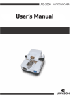
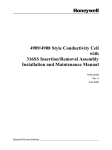
Lens Groover
User’s Manual
Content
Preoperation Instruction ............................................................... 2
Safety Precautions........................................................................................................... 2
Unwrap the Machine (From the package) ...................................................................... 3
Names of the Spare Parts ................................................................................................ 3
Operation of the Machine ............................................................. 4
Choose a Type of Grooving ............................................................................................. 4
(A)
Center grooving .................................................................................................... 4
(B)
Front-curved Grooving ......................................................................................... 5
(C)
Back -curved Grooving ......................................................................................... 5
Groove the lens ............................................................................................................... 6
Everyday Maintenance (Upkeep) .................................................................................... 6
Drainage Equipment........................................................................................................ 6
Sponge ............................................................................................................................. 7
Slide Bar ........................................................................................................................... 7
Replace the Cutting Wheel.............................................................................................. 7
Replace the Chuck Rubber .............................................................................................. 7
. Adjustment & Calibration .............................................................................................. 8
The adjustment of grooving position for center grooving .............................................. 8
Thorough Adjustment ..................................................................................................... 8
. Other Items ................................................................................................................... 8
Removal of Base Pedestal ............................................................................................... 8
Removel of Machine Top ................................................................................................ 8
Detailed Illustrations ..................................................................... 9
1
Preoperation Instruction
Safety Precautions
Warning
Don’t operate the machine before you read over and thoroughly grasp all
the instructions and rules. Any violation of the rules stated in the manual
may cause accidents such as fire, shock, personal injury etc.
In order to operate the machine and instruct others on the safe side all the
time, please read this manual carefully.
Note: The manufacturer of this machine is not responsible for or obliged to
any accident caused by a careless operator who pays no attention to the
rules of precautions related below.
[Precautions]
.Don’t use this machine for any other purposes than grooving lens of glasses.
.While the machine is working, don’t touch the cutting wheel to avoid getting
injured.
.When the electric power cannot reach the intensity demanded (voltage and
frequency), don’t use the machine .you have to be clear about the particular
condition of the power supply.
.Don't place the machine in high temperature or leave it exposed to strong
sunlight.
.If any liquid or other material conies into the machine, turn the switch off
immediately and pull die plug out of the wall socket. It cannot be operated again
until the machine is thoroughly checked and repaired by an expert in this line.
.No other spare parts can be fitted in the machine than its own elements.
.Don’t make the machine over-loaded or ram any of its spare parts.
.If the machine is left idle for a period of time please remove the plug out of the
wall socket.
2
Unwrap the Machine (From the package)
1. Open the carton, and take out the machine wrapped in the foamed
plastics.
2. Take the machine out carefully and place it on a big enough and quite
stable desk.
Accessories
When the automatic grooving machine is taken out, you’re advised to give
a check to the following accessories.
2 pcs spare sponge
2 pcs spare chuck rubber
Names of the Spare Parts
3
Operation of the Machine
Choose a Type of Grooving
Before a kind of lens is grooved, which type of grooving is to be chosen
should be decided. Raise the base pedestal (Fig 1) and under it, arrange
a controllable system of installation of the machine, which should be in
accordance with the following instructions and figures. In this way, you
can get your desirable effect.
(A) Center grooving
Suitable for: Thick lens; Thin lens with monothickness edges
To thick lens, center grooving is the most commonly used method while
this method is applied,the grooving is automatically going on in the
center between the front and back surfaces. This type of grooving
should be arranged according to the instructions related in Fig 2A.
1. Raise the base pedestal (Fig l). Insert
the two combined pins into the lower
holes marked with “C”
2. Fit the center pin between two
guide-bar arms.
3. Adjust the grooving positioner to the
central position.
[Note]
If need be, this method of arrangement is completely satisfactory.
(Please refer to “Adjustment & Calibration in Item 3” “maintenance &
Upkeep”)
4
(B) Front-curved Grooving
Suitable for: Lens with thick edges but thin center.
When the lens with thick edges but thin center is to be front-curved
grooved,the work should be done according to the procedure shown in
Fig 2 B.
1. Raise the base pedestal (Fig l) and insert the combined pins into the
holes “F” on the right and “C” on the left.
2. Remove the center pin to make it suspend in the air.
3. Check the lens to make sure it is lower than the lens receiver
(Fig l). Rotate the lens to make the
thinnest part of its edge touch the lens
receiver directly.
4. Close the guide -bar arm and rotate
the grooving positioner so that the edge
of lens can be removed to the desired
distance at which the lens can be grooved.
(C) Back -curved Grooving
Suitable for: Double -aimed glasses.
This type of grooving is rarely used for ordinary
lens. But it is of great use. When the machine
is set for this purpose, please operate it
according to the instructions shown in Fig 2C.
Place the combined pins in the positions”R” and “C” on the left. If the lens
to be grooved is a common lens, it can be treated as an ordinary thin lens
and grooved in the same way the thin lens is done. However,when the
lens to be worked on is the one for double-aimed glasses, you should adjust
the left guide -bar arm to the position you want to groove it. Then lightly
press the right part of the machine top (Fig l) to a position lower than that
of the base pedestal, making it reach the desired grooving depth (Fig 1).
Hold the right guide-bar arm to make it leave the front surface.
5
Groove the lens
When your automatic grooving machine has been arranged to the grooving
type you want, please do the job according to the following instruction.
1. The depth adjusting controller should be set at zero point and the two
switches should remain at “off,position (Refer to the operating positions
in Fig l).
2. Place the sponge between two straight plastic slices under the base
pedestal .Let the sponge take in as much water as possible by using the
assessor plastic sprinkler. Don’t add to much water to the machine.
3. Lower the base pedestal to the position at which it can be controlled. Check
the lens to see if it lies in the center. Make the clamp rotator tightened and
rotate it a quarter of a circle. Keep the front surface of the lens facing your
right all the time;
4. Open the guide-bar arms, Lightly lower the Lens to the position between
the two nylon guide bar rollers and help it enter the lens receiver .After you
have checked the machine through and are sure that each spare part is in
place, switch on the lens. Let the lens keep rotating for about a quarter of a
circle, Then make a check to see if the lens is tight enough between two
guide-bar rollers. Then switch on the cutting wheel and finally adjust the
depth adjusting controller to your desired depth.
5. After about sixty seconds, the sound of cutting may come to a change. That
means the grooving has been finished. Switch off the cutting wheel and the
lens successively. Raise the machine top.
[Note]
If you want to set the machine to deep groove a kind of hard lens (mineral),
first you should adjust the depth adjusting controller to half of the depth
you want, After the lens has been grooved for a circle (about sixty seconds),
read just the controller to your desired depth and make the lens rotate for
another circle.
Maintenance of the Machine (Upkeep)
Everyday Maintenance (Upkeep)
Drainage Equipment
This automatic grooving machine has a small drainage equipment not far in
front of its cutting wheel (Fig l).A stopper is fitted to the equipment to prevent
water form splashing out by accident. Suggest that the stopper be removed
6
forever so that too much water there won’t be stored to damage the bearings.
Bearings cannot prevent themselves from getting damaged by the water
splashing out. A small pool of water on your working desk is surely much cheapo
than two new bearings.
Sponge
The sponge should be washed often. Each time, before the sponge is used,
let it absorb as much water as possible. When the sponge is worn and broken, a
new piece should be replaced. Once the machine has finished working,you
should take the sponge out and wash the machine clean with it.
Slide Bar
In order to keep the machine top turning easily from one side to the other, the
side bar should often be cleaned with clean cloth. Occasionally it should also be
smeared with oil.
Replace the Cutting Wheel
When the cutting wheel need to be changed ,cut off the electric power first.
Then insert a small stick into the hole of the bar to make the wheel locked by the
screw and unable to move (Fig3)
[Warning]The cutting wheel should be replaced
properly (Fig3) so that it is suitable for the lens
receiver to be grooved (Fig 1).
Replace the Chuck Rubber
Open the lens chucks, remove the left chuck and the right one successively (Fig
l).Then you can of lens, so that the lens edge won't touch the right guide-bar arm.
easily move the chuck rubbers away and replace a new pair of rubbers to them.
7
. Adjustment & Calibration
The adjustment of grooving position for center grooving
When center grooving applied, the adjustment of grooving
position is the bust adjustment. If the grooving position is to
be moved to the back surface of the lens, rotate the
adjusting knob clockwise (Fig4),
If the grooving position is to be moved to the front surface of
the lens, rotate the adjusting knob the counter-clockwise
(Fig4).
Thorough Adjustment
Check and see whether “0”is in its correct position, make the
depth adjusting controller point at “0” position, Check if the
cutting wheel lies higher than the surface of lens receiver, If
the cutting wheel can’t be seen clearly just adjust the
“0”adjusting screw to the very end of the base pedestal.
. Other Items
Removal of Base Pedestal
To remove the base pedestal (Fig l), you have to insert a small
metal stick into the hole on the right side of the base bar,
These are the positions of two screw, Drive two screw into the
body of the main bar.
Removel of Machine Top
The slide bar is located in the top of the machine and extends
to a position lower than the main body, It is a moving bar with
two screw (Fig l), Insert a small metal rod into two holes of the
bar. The left bar rotates forward while the right one backward
When the bar is pressed to a certain extent you can easily
raise it from its position in the hole.
8
Detailed Illustrations
Lens Acceptable
Mineral/ plastic glasses
Attainable depth of grooving
0 – 0.7 mm
Width of grooving
0.6 mm
Acceptable of thickness of lens
1.5 – 11.0 mm
Acceptable diameter of lens
28 – 70 mm
Grooving time needed
About 60 seconds
Volume/Extent
170 (W)x 210(L) x 150(H) mm
Weight
2.7 kg
Power needed
□100 - 120 V/ 60 Hz AC
□200- 240 V/ 50 Hz AC 90 W
The description and lens’ exterior is changeable according to particular operation
conditions.
9