1
UM Space REU Final Report
Eric Haengel
August 11, 2011
Contents
1 Introduction.
1
2 Design and Methods.
1
3 Results.
4
4 Conclusion.
6
5 Appendix A: Power Output control for the CC430 radio.
7
6 Appendix B: RF tone generation and ADC12 code.
8
7 Appendix C: Data collection via arduino.
15
8 Appendix D: How to put together the sensor.
18
1
Introduction.
The purpose of this project was to develop a prototype sensing device which would be able to measure
accurately the dielectric constant of a surrounding fluid over a period of time. The ultimate goal is to
create an implementation of the device specified in Professor Roger DeRoo’s proposal “A low cost sensor
to quantify spatial and temporal variability of snow packs for SCLP validation.” In brief, this device will
be able to measure locally in a snow pack the snow density, moisture content, temperature, grain size,
and packing density of the snow. The device will be small and self-contained, so that it can be left in a
snowy region for some duration of time to capture data.
The sensor has several components to it, the main component being an open-circuit resonator tuned
to resonate in the ISM band. When this resonator is immersed in a dielectric material, the change in
resonant frequency and Q-value can be related to the dielectric constant of that material. In this way,
one can study the properties of a surrounding fluid or snow pack using this sensor.
Other important components of the sensor include a temperature sensor, a diode/photo detector pair
to measure snow density and grain diameter, and an RF transmitter to contact and send data periodically
to a base station. Significant development was only made on the open-circuit resonator component of
the sensor.
2
Design and Methods.
The MSP430. In order to create a standalone device which could measure the resonant frequency of
a resonator, a stable microprocessor capable of controlling an ISM band RF transmitter was necessary.
After some shopping around, it was decided to use TI’s CC430F5137, which is a relatively new device
that integrates an MSP430 microprocessor and a CC1101 RF transmitter onto the same board. This
device is able to transmit in three seperate frequency bands, but as for the band relevant to this project
it is able to transmit between around 820mhz and 960mhz, with a resolution of less than 1mhz.
1
More specifically, the device we used was the EMCC430F5137 development kit, which included two
boards, two antennae, two battery packs, and some pin headers. The cost of this develoment kit was
$150, and the programming cable (the MSP-FET430UIF) cost another $100.
The RF transmitter. The next step was to get the CC430 to act as a controllable RF tone generator,
but this was not the purpose that the CC430 was designed for. If one reads the user guide for the CC430,
it becomes clear immediately that the main purpose of the RF transmitter on the CC430 is for data
transmission between devices, not for continous tone generation. It took some toying around and work
to figure out a way to make it generate a tone, but we were eventually successful. The CC430 is able
to enter “infinite packet length transmission mode” if certain registers are set in the right way, and by
sending a null-packet the CC430 will emit a continuous tone at a set frequency (see Appendix B). It is
also possible to control the power level of the output of the device, but this is also a bit complicated (see
Appendix A).
The RF switch. In the end-product the RF transmitter on the CC430 device will have a dual-purpose.
It will be used to generate an RF tone to measure the resonant peak of the resonator, and it will be
used to send/receive information to/from a base station. In order to have both functions available, it is
necessary to have some kind of switching device on the RF transmitter, which can be used to turn on
or off the antenna and resonant sensing device. Professor DeRoo designed such a switch, and created a
small chip that can do this by using two RN731V PIN diodes. When DC current flows through one of
the PIN diodes on the chip, RF signals are able to transmit through it, but when there is no DC current
flow then the PIN diode allows no transmission.
One of the problems in getting the switch to work however is that it has a fairly specific power input
requirement. In order to get the PIN diodes to transmit, a voltage of around 1V has to be supplied, and
no more than 50ma at this voltage should be allowed. After some playing around we figured out that
the PIN diodes can be powered by the digital output pins on the CC430, because when they are used to
draw current, their output levels drop to around 0.8V which is enough to turn on the RF switch. (figure
out what the attenuation of the switch is again)
The RF Rectifier. The resonator chip has two ports, one of which was connected directly to the
CC430 RF emitter. The other end was connected to an LTC5505 RF Power Detector, which outputs
a voltage signal proportional to the amplitude of the incomming wave. By connecting the output of
the LTC5505 to an analog-to-digital converter (the ADC12 module on the CC430), we were able to
characterize the response of the resonator at different frequencies.
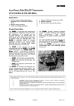
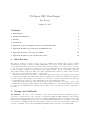
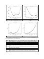
Early on, testing was done on the rectifier to understand how its output relates to the amplitude of
the incoming wave. It was found that the output is directly proportional to the amplitude, but that
the constant of proportionality depends slightly on frequency. In the end-product, an entirely different
rectifier chip may be used, but in any case it will be important to understand how the rectifier responds
at different frequencies.
2
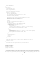
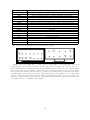
Plot of voltage output of the rectifier vs amplitude of incoming wave.
The amplitude of the incoming, constant frequency wave was measured with
a high quality RF power sensor.
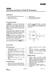
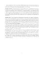
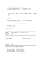
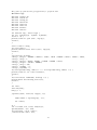
The Sensor Code. The CC430 microcontroller has on board a 12bit analog to digital converter, and
this was used to capture the output from the RF rectifier. A basic flow diagram of code used for sensing
is below:
The CC430 sends 100 bytes of a null message at a set frequency, and then the ADC12 is turned on to
capture the voltage of the rectifier. The CC430 continues to send another 900 bytes of a null message,
and then waits for the ADC12 data to be available. It then sends this data then to a computer, picks a
new frequency, and repeats. In this way the device sweeps through the entire frequency range within a
about a minute, and by using a program on the computer to store the output as it comes it is possible
to create a graph of the response of the resonator at different frequencies (see Results).
Data Output. The CC430 actually comes with several ways of implementing serial communication, so
that it can communicate with a computer. For example, there is an entire module on the CC430 dedicated
to UART serial communication. However, the CC430 does not come with a logic level conversion chip,
and RS232 uses a very different set of voltages than the CC430, so one had to be purchased separately.
Near the end of the project we did purchase such a chip, but it has yet to be implemented.
3
In the mean time, a really simple hack with a couple of digital output pins on the CC430 was used to
send data to a computer. One pin was designated the clock, and the other the data pin, and these were
hooked up to two digital input pins on an arduino. The arduino had code to read the data and then to
send it via a serial-to-usb cable to a computer.
3
Results.
After the sensor was put together, several tests were run. The most simple and primary test was to just
simply check that the resonance curve of the resonator as measured by the sensor matched that of the
network analyzer in Chris Ruf’s lab. Initially it did not, and this was because other elements of the
circuit were causing interference. A lot of time was spent in debugging these issues, and characterizing
them. Once that was taken care of, some experiments were run with the resonator dipped into a few
types of solvents (hexane, heptane, and toluene). Harvey Elliot wrote a report ”Characterization of
a Microwave Resonator” in April, 2011 in which he describes experiments that he performed on some
of the very same resonators that we were using to test our sensor. He collected data using a network
analyzer on the response of the resonator to the same solvents that we used, so his paper was used as
both a guide and a basis for comparison to our own results.
In debugging the sensing device, several things were noted: The blue cables (see picture) we were
using have some kind of response in the frequency range we are using, so they cause some interference.
The rectifier itself gives an output which is proportional to the amplitude of the incoming wave, but this
proportionality constant depends on frequency to some small degree. Furthermore, the rectifier can only
reliably measure amplitude if the amplitude is sufficiently high, so if the power drop across the rectifier
or some other element of the circuit is too great then the data becomes useless. Also the resonant sensor
itself is very sensitive, so it is important to isolate it as much as possible from nearby objects.
One tool we used to attempt to eliminate some of the interference was a 3db attenuator on the output of the CC430 RF emitter. This helped to remove any part of the wave which was reflected by the
resonator, and in some cases was had a significant effect.
Data collected with two cables in series.
Two cables in series + a 3db attenuator.
4
An early run of the sensor. The power on the emitter
was too low, so the response was in the noise floor.
Data collected with resonator, no cables.
A direct connection of the RF emitter to the
rectifier.
Same experiment but with 3db attenuator.
A large amount of data was gathered over several days. Here is a table that briefly summarizes what
sorts of experiments were run on which days.
jul11
jul13
jul14
jul19
jul21
jul22
jul25
jul27
aug01
First runs of sensor.
Tests with one cable, two cables, and attenuator. Direct connection at different power
settings, and resonator with/without cables or attenuator at different power settings.
Resonator without cable. Attempts to shift the peak with various objects.
RF switch by itself, and with resonator.
Not entirely sure! Probably just more random testing.
Full setup of prototype sensor with resonator in beaker. Tests done with Hexane.
3dbm attenuator used, and beakers filled to various levels (full, quarter, etc).
Data collected with cables again, but this time in the beaker. All three resonators were
tested when emersed in hexane.
Some random tests with res1 and res2.
Resonator 2 tested with heptane and toluene. Several runs were done with both fluids
at various emersion levels (resonator right above fluid, just touching, slightly below,
1cm below, etc).
5
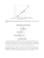
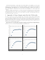
To illustrate the sensitivity at the very tip of the resonator chips, here are some experiments done
with resonator 2 and hexane. The first run was done with the resonator slightly above the fluid, and
then each successive run was done by lowering it very slightly (less than 5mm each time).
4
Resonator right above fluid
Resonator tip touching fluid
Resonator right below fluid
Resonator slightly more below fluid
Conclusion.
The sensor in its current state still needs a lot of work before it can be put to use in the field. One very
important thing that needs to be done is to design a better resonator chip which would be more suitable to
the end-goal. The frequency band that the CC430 can emit RF tones at is rather limited, so the resonator
will need to be tuned carefully to resonate in that frequency range whether it is surrounded by air, or
densely packed snow. The resonator will likely need to be very carefully designed with electromagnetic
modelling software.
There are many other smaller issues to be worked on as well, such as making the device run on very
low power, so that it can survive in a snow pack for a long period of time. It also is important to figure
out how to get the CC430 to reliably transmit/receive information over the radio, so that a base station
can be used to control several sensors remotely. It will be nice and much more convenient if the serial
communication module on the CC430 is figured out, so that an arduino is not necessary to read data off
of it.
6
Another important thing to consider will be the possible inclusion of an amplifier on one end of the
resonator device. The rectifier can only reliably measure amplitude of an incoming wave if the amplitude
is sufficiently high, and this has lead us to, at least for now, always use the CC430 radio at max power
when running the sensor. This may not be the ideal situation if we wish to conserve power over time– it
may be more efficient to run the radio at low power, but to use an amplifier to boost the output of the
resonator.
Two more sensing components need to be worked out as well: the temperature sensor, and the packing
density/grain diameter sensor. These are theoretically simpler to implement than the resonant sensor,
but will still require some amount of work. More details on how these components will work can be
found in Professor DeRoo’s proposal.
5
Appendix A: Power Output control for the CC430 radio.
In order to control the power output of the RF module on the CC430, a register called the PAtable must
be set. The PAtable actually have eight channels, and there is another register that allows one to choose
which power setting is actually put to use, but so far it hasn’t been necessary to make use of this feature.
The way that the register value corresponds to output power works is a bit unclear and complicated, but
luckily some nice person wrote a report (TI report swra151a) which lists the various output powers one
should expect for different PAtable values.
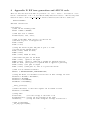
The output power of the RF emitter is frequency dependent, and this may be an important fact to
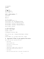
consider later. Below are some graphs of frequency vs emitted power. Note that a 30dbm attenuator
was used so as to not overload the expensive RF power measuring device.
PAtable set to 0xC0
PAtable set to 0x70
PAtable set to 0x3E
PAtable set to 0xB5
7
6
Appendix B: RF tone generation and ADC12 code.
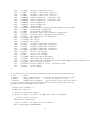
There are three files used in the RF tone generation code: main.c, utilities.c, and utilities.h. main.c
has the overall structure of the code, and calls the utility functions in utilities.c. The most important
function in utilities.c is the send tone with adc function, which is described in more detail below.
Code for main.c:
#include "utilities.h"
void main() {
//turn off the watchdog timer
WDTCTL = WDTPW + WDTHOLD;
//send byte 0xCC to arduino
dataWrite(0x03, 0x05, 0xCC);
//turn on the LEDs, BIT6 on port 3 is the red one,
//and BIT0 on port 1 is the green one
P3DIR |= BIT6;
P1DIR |= 0x01;
//setup the switch on pin0 and pin7 of port 3 to turn
//on and off the sensing device
P3DIR |= BIT0; P3DIR &= ~BIT7;
P3REN |= BIT7;
P3OUT |= BIT0; P3OUT &= ~BIT7;
//Initialize the pins for the ADC12
P2SEL |= BIT0; //pin0 is the input
P2REN |= BIT1; //pin1 is connected to ground via pulldown resistor
P2OUT &= ~BIT1; //sets pin1 to be pulled down as opposed to pulled up
P2DIR |= BIT7; //set pin7 as output
P2OUT |= BIT7; //turn pin7 on, this is to power the switch
//turn on 2.5V internal reference
REFCTL0 |= REFMSTR+REFVSEL_2+REFON+REFTCOFF;
//setup the ADC12, see datasheet for more info on what settings are used
ADC12CTL0 = ADC12ON + ADC12SHT02;
ADC12CTL1 = ADC12SHP;
ADC12CTL2 |= ADC12REFOUT;
ADC12MCTL0 = ADC12SREF_1;
__delay_cycles(75);
//enable the ADC12, so that data capture can be turned on later
ADC12CTL0 |= ADC12ENC;
//setup radio
SetVCore(2);
//set the voltage of the radio to 2V
ResetRadioCore(); //reset all the settings on the radio
InitRadio();
//setup the radio using the settings in utilities.c
//turn on interrupts
__bis_SR_register(GIE);
8
__no_operation();
volatile int i=3, k=0, j=0;
while(1) {
//depending on the input to Port3.7, turn on/off the snow sensor
if(P3IN & BIT7) { P2OUT |= BIT7; P3OUT |= BIT6; }
else { P2OUT &= ~BIT7; P3OUT &= ~BIT6; }
//turn on the radio at the set frequency, and send 1000 bytes of
//the message "bbbbb..." After first 100 bytes the ADC12 captures
//the voltage on the rectifier, and then after the 1000 bytes are
//transmitted the ADC12 reading is sent to the arduino
send_tone_with_adc(0x20 + k, 16*i, 0x00, 1000);
i++;
if(i == 16) { i=0; k++; }
if(k==5) k=0;
}
}
code for utilities.h: (some pieces are omitted as not really relevant, but are left in the code as
examples of other things that can be done)
#include "cc430x513x.h"
#define
#define
#define
#define
#define
PACKET_LEN
RSSI_IDX
CRC_LQI_IDX
CRC_OK
PATABLE_VAL
(0x3C) // PACKET_LEN <= 61
(PACKET_LEN)
// Index of appended RSSI
(PACKET_LEN+1) // Index of appended LQI, checksum
(BIT7)
// CRC_OK bit
(0xC0)
// 0 dBm output 0x51 orig
/*******************
* Function Definition
*/
void Transmit(unsigned char *buffer, unsigned char length);
void ReceiveOn(void);
void ReceiveOff(void);
void InitButtonLeds(void);
void InitRadio(void);
void InitRadio_pwr(int pwr);
void dataWrite(int pin_clk, int pin_out, int data);
void send_tone(char freq_h, char freq_m, char freq_l, int duration);
void send_tone_with_adc(char freq_h, char freq_m, char freq_l, int duration);
/* -----------------------------------------------------------------------------------------------*
Defines
* -----------------------------------------------------------------------------------------------*/
#define PMM_STATUS_OK
0
#define PMM_STATUS_ERROR 1
/********************
* Variable definition
*/
9
typedef struct S_RF_SETTINGS
unsigned char fsctrl1;
unsigned char fsctrl0;
unsigned char freq2;
unsigned char freq1;
unsigned char freq0;
unsigned char mdmcfg4;
unsigned char mdmcfg3;
unsigned char mdmcfg2;
unsigned char mdmcfg1;
unsigned char mdmcfg0;
unsigned char channr;
unsigned char deviatn;
unsigned char frend1;
unsigned char frend0;
unsigned char mcsm0;
unsigned char foccfg;
unsigned char bscfg;
unsigned char agcctrl2;
unsigned char agcctrl1;
unsigned char agcctrl0;
unsigned char fscal3;
unsigned char fscal2;
unsigned char fscal1;
unsigned char fscal0;
unsigned char fstest;
unsigned char test2;
unsigned char test1;
unsigned char test0;
unsigned char fifothr;
unsigned char iocfg2;
unsigned char iocfg0;
unsigned char pktctrl1;
unsigned char pktctrl0;
unsigned char addr;
unsigned char pktlen;
} RF_SETTINGS;
{
//
//
//
//
//
//
//
//
//
//
//
//
//
//
//
//
//
//
//
//
//
//
//
//
//
//
//
//
//
//
//
//
//
//
//
Frequency synthesizer control.
Frequency synthesizer control.
Frequency control word, high byte.
Frequency control word, middle byte.
Frequency control word, low byte.
Modem configuration.
Modem configuration.
Modem configuration.
Modem configuration.
Modem configuration.
Channel number.
Modem deviation setting (when FSK modulation is enabled).
Front end RX configuration.
Front end RX configuration.
Main Radio Control State Machine configuration.
Frequency Offset Compensation Configuration.
Bit synchronization Configuration.
AGC control.
AGC control.
AGC control.
Frequency synthesizer calibration.
Frequency synthesizer calibration.
Frequency synthesizer calibration.
Frequency synthesizer calibration.
Frequency synthesizer calibration control
Various test settings.
Various test settings.
Various test settings.
RXFIFO and TXFIFO thresholds.
GDO2 output pin configuration
GDO0 output pin configuration
Packet automation control.
Packet automation control.
Device address.
Packet length.
void ResetRadioCore (void);
unsigned char Strobe(unsigned char strobe);
void WriteRfSettings(RF_SETTINGS *pRfSettings);
void WriteSingleReg(unsigned char addr, unsigned char value);
void WriteBurstReg(unsigned char addr, unsigned char *buffer, unsigned char count);
unsigned char ReadSingleReg(unsigned char addr);
void ReadBurstReg(unsigned char addr, unsigned char *buffer, unsigned char count);
void WriteSinglePATable(unsigned char value);
void WriteBurstPATable(unsigned char *buffer, unsigned char count);
code for utilities.c: (again some stuff was omitted, but is left in the actual code file)
#include "utilities.h"
RF_SETTINGS rfSettings = {
0x08,
// FSCTRL1
Frequency synthesizer control.
10
0x00,
0x23,
0x31,
0x3B,
0xCC,
0xFF,
0x90,
0x22,
0xF8,
0x00,
0x34,
0x56,
0x10,
0x18,
0x16,
0x6C,
0x43,
0x40,
0x91,
0xE9,
0x2A,
0x00,
0x1F,
0x59,
0x81,
0x35,
0x09,
0x47,
0x29,
0x06,
0x00,
0x00,
0x00,
0x30
//
//
//
//
//
//
//
//
//
//
//
//
//
//
//
//
//
//
//
//
//
//
//
//
//
//
//
//
//
//
//
//
//
//
FSCTRL0
FREQ2
FREQ1
FREQ0
MDMCFG4
MDMCFG3
MDMCFG2
MDMCFG1
MDMCFG0
CHANNR
DEVIATN
FREND1
FREND0
MCSM0
FOCCFG
BSCFG
AGCCTRL2
AGCCTRL1
AGCCTRL0
FSCAL3
FSCAL2
FSCAL1
FSCAL0
FSTEST
TEST2
TEST1
TEST0
FIFOTHR
IOCFG2
IOCFG0
PKTCTRL1
PKTCTRL0
ADDR
PKTLEN
Frequency synthesizer control.
Frequency control word, high byte.
Frequency control word, middle byte.
Frequency control word, low byte.
Modem configuration. (originally 0xCA)
Modem configuration. (originally 0x83)
Modem configuration. (originally 0x93)
Modem configuration.
Modem configuration.
Channel number.
Modem deviation setting (when FSK modulation is enabled).
Front end RX configuration.
Front end TX configuration.
Main Radio Control State Machine configuration.
Frequency Offset Compensation Configuration.
Bit synchronization Configuration.
AGC control.
AGC control.
AGC control.
Frequency synthesizer calibration.
Frequency synthesizer calibration.
Frequency synthesizer calibration.
Frequency synthesizer calibration.
Frequency synthesizer calibration.
Various test settings.
Various test settings.
Various test settings.
RXFIFO and TXFIFO thresholds.
GDO2 output pin configuration.
R Studio User Manual for de
GDO0 output pin configuration. Refer to SmartRF^
A
Packet automation control.
Packet automation control. (originally 0x04)
Device address.
Packet length.
};
// *****************************************************************************
// @fn
Strobe
// @brief
Send a command strobe to the radio. Includes workaround for RF1A7
// @param
unsigned char strobe
The strobe command to be sent
// @return
unsigned char statusByte
The status byte that follows the strobe
// *****************************************************************************
unsigned char Strobe(unsigned char strobe)
{
unsigned char statusByte = 0;
unsigned int gdo_state;
// Check for valid strobe command
if((strobe == 0xBD) || ((strobe >= RF_SRES) && (strobe <= RF_SNOP)))
{
// Clear the Status read flag
RF1AIFCTL1 &= ~(RFSTATIFG);
// Wait for radio to be ready for next instruction
while( !(RF1AIFCTL1 & RFINSTRIFG));
11
// Write the strobe instruction
if ((strobe > RF_SRES) && (strobe < RF_SNOP))
{
gdo_state = ReadSingleReg(IOCFG2);
// buffer IOCFG2 state
WriteSingleReg(IOCFG2, 0x29);
// chip-ready to GDO2
RF1AINSTRB = strobe;
if ( (RF1AIN&0x04)== 0x04 )
// chip at sleep mode
{
if ( (strobe == RF_SXOFF) || (strobe == RF_SPWD) || (strobe == RF_SWOR) ) { }
else
{
while ((RF1AIN&0x04)== 0x04);
// chip-ready ?
// Delay for ~810usec at 1.05MHz CPU clock, see erratum RF1A7
__delay_cycles(850);
}
}
WriteSingleReg(IOCFG2, gdo_state);
// restore IOCFG2 setting
while( !(RF1AIFCTL1 & RFSTATIFG) );
}
else
// chip active mode (SRES)
{
RF1AINSTRB = strobe;
}
statusByte = RF1ASTATB;
}
return statusByte;
}
// *****************************************************************************
// @fn
ResetRadioCore
// @brief
Reset the radio core using RF_SRES command
// @param
none
// @return
none
// *****************************************************************************
void ResetRadioCore (void)
{
Strobe(RF_SRES);
// Reset the Radio Core
Strobe(RF_SNOP);
// Reset Radio Pointer
}
// *****************************************************************************
// @fn
WriteRfSettings
// @brief
Write the minimum set of RF configuration register settings
// @param
RF_SETTINGS *pRfSettings Pointer to the structure that holds the rf settings
// @return
none
// *****************************************************************************
void WriteRfSettings(RF_SETTINGS *pRfSettings) {
WriteSingleReg(FSCTRL1, pRfSettings->fsctrl1);
WriteSingleReg(FSCTRL0, pRfSettings->fsctrl0);
WriteSingleReg(FREQ2,
pRfSettings->freq2);
WriteSingleReg(FREQ1,
pRfSettings->freq1);
WriteSingleReg(FREQ0,
pRfSettings->freq0);
WriteSingleReg(MDMCFG4, pRfSettings->mdmcfg4);
12
WriteSingleReg(MDMCFG3,
WriteSingleReg(MDMCFG2,
WriteSingleReg(MDMCFG1,
WriteSingleReg(MDMCFG0,
WriteSingleReg(CHANNR,
WriteSingleReg(DEVIATN,
WriteSingleReg(FREND1,
WriteSingleReg(FREND0,
WriteSingleReg(MCSM0 ,
WriteSingleReg(FOCCFG,
WriteSingleReg(BSCFG,
WriteSingleReg(AGCCTRL2,
WriteSingleReg(AGCCTRL1,
WriteSingleReg(AGCCTRL0,
WriteSingleReg(FSCAL3,
WriteSingleReg(FSCAL2,
WriteSingleReg(FSCAL1,
WriteSingleReg(FSCAL0,
WriteSingleReg(FSTEST,
WriteSingleReg(TEST2,
WriteSingleReg(TEST1,
WriteSingleReg(TEST0,
WriteSingleReg(FIFOTHR,
WriteSingleReg(IOCFG2,
WriteSingleReg(IOCFG0,
WriteSingleReg(PKTCTRL1,
WriteSingleReg(PKTCTRL0,
WriteSingleReg(ADDR,
WriteSingleReg(PKTLEN,
pRfSettings->mdmcfg3);
pRfSettings->mdmcfg2);
pRfSettings->mdmcfg1);
pRfSettings->mdmcfg0);
pRfSettings->channr);
pRfSettings->deviatn);
pRfSettings->frend1);
pRfSettings->frend0);
pRfSettings->mcsm0);
pRfSettings->foccfg);
pRfSettings->bscfg);
pRfSettings->agcctrl2);
pRfSettings->agcctrl1);
pRfSettings->agcctrl0);
pRfSettings->fscal3);
pRfSettings->fscal2);
pRfSettings->fscal1);
pRfSettings->fscal0);
pRfSettings->fstest);
pRfSettings->test2);
pRfSettings->test1);
pRfSettings->test0);
pRfSettings->fifothr);
pRfSettings->iocfg2);
pRfSettings->iocfg0);
pRfSettings->pktctrl1);
pRfSettings->pktctrl0);
pRfSettings->addr);
pRfSettings->pktlen);
}
void send_tone_with_adc(char freq_h, char freq_m, char freq_l, int duration) {
Strobe(RF_SIDLE);
WriteSingleReg(FREQ2,
freq_h);
WriteSingleReg(FREQ1,
freq_m);
WriteSingleReg(FREQ0,
freq_l);
WriteSingleReg(PKTCTRL0, 0x02);
WriteSingleReg(PKTLEN,
(duration%256));
Strobe(RF_SNOP);
unsigned char *buffer = (unsigned char*)"ab";
volatile int i=0, j=0;
Strobe(RF_STX);
while (!(RF1AIFCTL1 & RFINSTRIFG));
// Wait for the Radio to be ready for next instruction
RF1AINSTRW = ((RF_REGWR | RF_TXFIFOWR)<<8 ) + duration; // Send address + Instruction
for(j=0; j<1500; j++);
dataWrite(0x03, 0x05, (freq_h<<8) + freq_m);
for(j=0; j<1500; j++);
for(j = 1; j < duration; j++) {
//after 100 bytes turn on the ADC
if(j == (duration-100)) ADC12CTL0 |= ADC12SC;
RF1ADINB = buffer[1];
while (!(RFDINIFG & RF1AIFCTL1));
13
}
j = RF1ADOUTB;
while(!(ADC12IFG & BIT0));
dataWrite(0x03, 0x05, ADC12MEM0);
Strobe(RF_SIDLE);
WriteSingleReg(PKTCTRL0, 0x00);
Strobe(RF_SNOP);
}
void dataWrite(int pin_clk, int pin_out, int data) {
P2DIR |= ((1 << pin_clk) | (1 << pin_out)); //turn on clk/out pin
P2OUT &= ~((1 << pin_clk) | (1 << pin_out)); //turn off everything
WDTCTL = WDTPW + WDTCNTCL;
volatile int i=0, j=0;
for(i=0; i<100; i++); //wait a second for the i/o to transition
//loop to print out data
for(i=0; i<16; i++) {
//(15-i) = current bit thats being output
//if 1, output 1 on pin_out, otherwise output 0 on pin_out
if(data & (1 << (15-i))) P2OUT |= (1 << pin_out);
else P2OUT &= ~(1 << pin_out);
//update
P2OUT ^=
WDTCTL =
for(j=0;
the clock and wait a short while for the i/o transitions
(1 << pin_clk);
WDTPW + WDTCNTCL;
j<100; j++);
}
P2OUT &= ~((1 << pin_clk) | (1 << pin_out));
}
void InitRadio(void) {
// Set the High-Power Mode Request Enable bit so LPM3 can be entered
// with active radio enabled
PMMCTL0_H = 0xA5;
PMMCTL0_L |= PMMHPMRE_L;
PMMCTL0_H = 0x00;
WriteRfSettings(&rfSettings);
WriteSinglePATable(PATABLE_VAL);
}
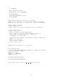
Here is a flow chart for how the send tone with adc function works:
14
7
Appendix C: Data collection via arduino.
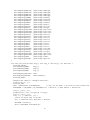
Below is the code used to get data off of the CC430 via the arduino. There are three pins used: The
ground pin of the arduino is connected to a grounded i/o pin on the CC430, pin 7 is used as input for
the clock, and pin 2 is used as input for data. Also, there are two modes by which the arduino sends
data over the serial port to the computer. One is sensor mode, and the other is bit mode (see code).
int old_state, state;
int count=0;
unsigned int value=0;
//mode=0 means sensor mode, it will output the data in the format:
//frequency
//voltage
//where voltage corresponds to the voltage measured on the rectifier
//mode=1 means bit mode, and it just prints out bit-by-bit the word
//sent by the CC430
int mode=0;
//initialize
void setup()
pinMode(2,
pinMode(7,
the pins on the arduino
{
INPUT); //Data
INPUT); //Clock
15
Serial.begin(9600);
}
void loop() {
//read from the clock
state = digitalRead(7);
//if clock transitioned, read data
if(state != old_state) {
int buf = digitalRead(2);
//if in bit-mode just send each bit as it comes
if(mode==1) Serial.print(buf);
//keep track of the overall word by setting bits in value
if(buf == 1) value |= (1 << (15-count));
else value &= ~(1 << (15-count));
count++;
if(count == 8 && mode==1) Serial.print(’ ’);
if(count == 16) {
//if mode=0, print out the frequency/voltage
if(mode == 0) {
if(2.5*(float(value)/4095.0) < 5) {
Serial.print(’ ’);
//value is just an integer, so convert it to actual voltage
Serial.print(2.5*(float(value)/4095.0), DEC);
}
else {
Serial.print(’ ’);
//value is just an integer, so convert it to the actual frequency
Serial.print(float(value)*0.1015625, DEC);
}
}
Serial.print(’\n’);
value = 0;
count=0;
}
}
//hold the current state, so that it can be compared to the old one
old_state = state;
}
The format of the serial output in sensor mode from the arduino is
Frequency (in Mhz)
Voltage on rectifier
Frequency (in Mhz)
Voltage on rectifier
...
The CC430 constantly sweeps across the frequency range. There is a C program which was used to
get data from the arduino over the serial port. The syntax is ”./resonance (serial port) (output file)”.
The output can be graphed with a python program graph res.py, but any graphing program can be used.
16
The python program uses the pybiggles library to graph the data.
Resonance.cpp:
#include
#include
#include
#include
#include
#include
#include
#include
<termios.h>
<stdlib.h>
<string.h>
<unistd.h>
<fcntl.h>
<stdio.h>
<math.h>
<time.h>
int main(int argc, char** argv) {
int fd = open(argv[1], O_RDWR | O_NOCTTY);
if(fd == -1) {
printf("Could not open %s\n", argv[1]);
return 1;
}
struct termios config;
if(!isatty(fd)) {
printf("Invalid serial device %s\n", argv[1]);
return 1;
}
tcgetattr(fd, &config);
config.c_iflag &= ~(IGNBRK | BRKINT | ICRNL | INLCR | PARMRK | INPCK | ISTRIP | IXON);
config.c_oflag = 0;
config.c_lflag &= ~(ECHO | ECHONL | ICANON | IEXTEN | ISIG);
config.c_cflag &= ~(CSIZE | PARENB);
config.c_cflag |= CS8;
config.c_cc[VMIN] = 1;
config.c_cc[VTIME] = 0;
if(cfsetispeed(&config, B9600) < 0 || cfsetospeed(&config, B9600) < 0) {
printf("Could not set correct baud\n");
return 1;
}
if(tcsetattr(fd, TCSAFLUSH, &config) < 0) {
printf("Error initializing device\n");
return 1;
}
int len=0;
char buf[1024];
buf[0] = 1;
//printf("%d\n", write(fd, argv[2], 1));
FILE* handle = fopen(argv[2], "w");
int count=0;
do {
len = read(fd, buf, 1024); buf[len]=0;
fprintf(handle, "%s", buf);
if(strstr(buf, "\n")) count++;
} while(len && count < 400);
17
fclose(handle);
close(fd);
return 0;
}
graph res.py:
#!/usr/bin/python
import biggles, sys
handle = open(sys.argv[1], "r")
lines = handle.readlines()
lines.pop(0)
freq = []
amp = []
for line in lines:
line = line.replace("\n", "")
if(float(line) < 500): amp.append(float(line))
if(float(line) >= 500): freq.append(float(line))
while(len(amp) > len(freq)): amp.pop(len(amp)-1)
while(len(amp) < len(freq)): freq.pop(len(freq)-1)
print len(amp), len(freq)
p = biggles.FramedPlot()
p.title = "Power vs Freq"
p.xlabel = "Freq in Mhz"
p.ylabel = "Volts"
p.add(biggles.Points(freq, amp))
print "max freq, amp:", freq[amp.index(max(amp))], max(amp)
p.show()
p.write_img(400, 400, sys.argv[1].replace("dat", "png"))
8
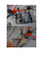
Appendix D: How to put together the sensor.
Here is a list of all of the components of the sensor:
1. The CC430.
2. The programmer cable.
3. The rainbow colored ribbon cable.
4. The RF switch.
5. The Resonator. (There are three of them so far)
6. The Rectifier, and the cable that connects to it.
7. The Arduino.
8. The battery pack, and its cable for connecting to the CC430 board.
18
9. Lots of alligator clips to connect various components together.
Here are some hopefully useful pictures to guide someone towards putting together the current version
of the device:
19
Here is a table of the various chips used, and their pinouts:
20
Pin name
CC430
VCC
GND
ADC12
CLK
DATA
TXEN
Port 3, pins 0 and 7
RF Switch
TXEN
RXEN
TXBIAS
GND
Rectifier
VCC
GND
EN
VOUT
Description
Used to power the rectifier, outputs 3V.
Used as common ground for rectifier, RF switch, and Arduino.
Used to capture voltage reading from RF switch.
Used to synchronize communication with the Arduino.
Used in conjunction with CLK to send data to the Arduino.
Enable the TX pin on the RF switch, to turn on the Snow Sensor.
Connect these two to turn on the Snow Sensor, or disconnect to turn it off.
Enable transmission across the switch.
Not used.
Not used.
Common ground.
Power from CC430
Common ground.
Enable pin, for the moment this is tied to VCC
Output signal, connected to the ADC12 on the CC430
Here are two pinout diagrams, one for each of the two cables:
Rainbow connector pinout
Rectifier cable pinout
Finally, some notes: Make sure to connect power to the rectifier, or your data will come out as
completely flat every time (its very easy to forget!). To write a program to the board, connect it to
the programming cable and make sure that the programming cable is connected to the computer. Right
click on the project folder you wish to compile in the Code Composer window, and choose ”Set as Active
Project” if it is not already set as the active project. The project that is used for collecting sensor data is
”CC430 ADC12.” Once you have done this, to upload the program to the CC430 go to one of the menues
on the top, and click ”Debug Active Project.” After everything settles and the project is compiled, you
will have to either click the green arrow that appears in the debug window, or use the shortcut key F8
to actually start the code running on the CC430.
21


![Hacking Medical Devices - [media.blackhat.com]](http://vs1.manualzilla.com/store/data/005931227_1-f7547ce2b3ff0825b843d9b1dbb48800-150x150.png)