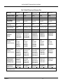
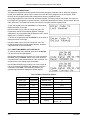
1
User’s Manual Model 218 Temperature Monitor Includes Coverage For: Model 218S and Model 218E Lake Shore Cryotronics, Inc. 575 McCorkle Blvd. Westerville, Ohio 43082-8888 USA Internet Addresses: [email protected] [email protected] Visit Our Website: www.lakeshore.com Fax: (614) 891-1392 Telephone: (614) 891-2243 Methods and apparatus disclosed and described herein have been developed solely on company funds of Lake Shore Cryotronics, Inc. No government or other contractual support or relationship whatsoever has existed which in any way affects or mitigates proprietary rights of Lake Shore Cryotronics, Inc. in these developments. Methods and apparatus disclosed herein may be subject to U.S. Patents existing or applied for. Lake Shore Cryotronics, Inc. reserves the right to add, improve, modify, or withdraw functions, design modifications, or products at any time without notice. Lake Shore shall not be liable for errors contained herein or for incidental or consequential damages in connection with furnishing, performance, or use of this material. Revision 2.4 P/N 119-007 20 February 2015 Lake Shore Model 218 Temperature Monitor User’s Manual LIMITED WARRANTY STATEMENT WARRANTY PERIOD: THREE (3) YEARS 1.Lake Shore warrants that products manufactured by Lake Shore (the "Product") will be free from defects in materials and workmanship for three years from the date of Purchaser's physical receipt of the Product (the "Warranty Period"). If Lake Shore receives notice of any such defects during the Warranty Period and the defective Product is shipped freight prepaid back to Lake Shore, Lake Shore will, at its option, either repair or replace the Product (if it is so defective) without charge for parts, service labor or associated customary return shipping cost to the Purchaser. Replacement for the Product may be by either new or equivalent in performance to new. Replacement or repaired parts, or a replaced Product, will be warranted for only the unexpired portion of the original warranty or 90 days (whichever is greater).. 2.Lake Shore warrants the Product only if the Product has been sold by an authorized Lake Shore employee, sales representative, dealer or an authorized Lake Shore original equipment manufacturer (OEM). 3.The Product may contain remanufactured parts equivalent to new in performance or may have been subject to incidental use when it is originally sold to the Purchaser. 4.The Warranty Period begins on the date of Purchaser's physical receipt of the Product or later on the date of operational training and verification (OT&V) of the Product if the service is performed by Lake Shore, provided that if the Purchaser schedules or delays the Lake Shore OT&V for more than 30 days after delivery then the Warranty Period begins on the 31st day after Purchaser's physical receipt of the Product. 5.This limited warranty does not apply to defects in the Product resulting from (a) improper or inadequate installation (unless OT&V services are performed by Lake Shore), maintenance, repair or calibration, (b) fuses, software, power surges, lightning and nonrechargeable batteries, (c) software, interfacing, parts or other supplies not furnished by Lake Shore, (d) unauthorized modification or misuse, (e) operation outside of the published specifications, (f) improper site preparation or site maintenance (g) natural disasters such as flood, fire, wind, or earthquake, or (h) damage during shipment other than original shipment to you if shipped through a Lake Shore carrier. 6.This limited warranty does not cover: (a) regularly scheduled or ordinary and expected recalibrations of the Product; (b) accessories to the Product (such as probe tips and cables, holders, wire, grease, varnish, feed throughs, etc.); (c) consumables used in conjunction with the Product (such as probe tips and cables, probe holders, sample tails, rods and holders, ceramic putty for mounting samples, Hall sample cards, Hall sample enclosures, etc.); or, (d) non-Lake Shore branded Products that are integrated with the Product. 7. To the extent allowed by applicable law,, this limited warranty is the only warranty applicable to the Product and replaces all other warranties or conditions, express or implied, including, but not limited to, the implied warranties or conditions of merchantability and fitness for a particular purpose. Specifically, except as provided herein, Lake Shore undertakes no responsibility that the products will be fit for any particular purpose for which you may be buying the Products. Any implied warranty is limited in duration to the warranty period. No oral or written information, or advice given by the Company, its Agents or Employees, shall create a warranty or in any way increase the scope of this limited warranty. Some countries, states or provinces do not allow limitations on an implied warranty, so the above limitation or exclusion might not apply to you. This warranty gives you specific legal rights and you might also have other rights that vary from country to country, state to state or province to province. 8.Further, with regard to the United Nations Convention for International Sale of Goods (CISC,) if CISG is found to apply in relation to this agreement, which is specifically disclaimed by Lake Shore, then this limited warranty excludes warranties that: (a) the Product is fit for the purpose for which goods of the same description would ordinarily be used, (b) the Product is fit for any particular purpose expressly or impliedly made known to Lake Shore at the time of the conclusion of the contract. (c) the Product is contained or packaged in a manner usual for such goods or in a manner adequate to preserve and protect such goods where it is shipped by someone other than a carrier hired by Lake Shore. 9. Lake Shore disclaims any warranties of technological value or of non-infringement with respect to the Product and Lake Shore shall have no duty to defend, indemnify, or hold harmless you from and against any or all damages or costs incurred by you arising from the infringement of patents or trademarks or violation or copyrights by the Product. 10.THIS WARRANTY IS NOT TRANSFERRABLE. This warranty is not transferrable. 11.Except to the extent prohibited by applicable law, neither Lake Shore nor any of its subsidiaries, affiliates or suppliers will be held liable for direct, special, incidental, consequential or other damages (including lost profit, lost data, or downtime costs) arising out of the use, inability to use or result of use of the product, whether based in warranty, contract, tort or other legal theory, regardless whether or not Lake Shore has been advised of the possibility of such damages. Purchaser's use of the Product is entirely at Purchaser's risk. Some countries, states and provinces do not allow the exclusion of liability for incidental or consequential damages, so the above limitation may not apply to you. 12.This limited warranty gives you specific legal rights, and you may also have other rights that vary within or between jurisdictions where the product is purchased and/or used. Some jurisdictions do not allow limitation in certain warranties, and so the above limitations or exclusions of some warranties stated above may not apply to you. 13.Except to the extent allowed by applicable law, the terms of this limited warranty statement do not exclude, restrict or modify the mandatory statutory rights applicable to the sale of the product to you. CERTIFICATION Lake Shore certifies that this product has been inspected and tested in accordance with its published specifications and that this product met its published specifications at the time of shipment. The accuracy and calibration of this product at the time of shipment are traceable to the United States National Institute of Standards and Technology (NIST); formerly known as the National Bureau of Standards (NBS). FIRMWARE LIMITATIONS Lake Shore has worked to ensure that the Model 218 firmware is as free of errors as possible, and that the results you obtain from the instrument are accurate and reliable. However, as with any computer-based software, the possibility of errors exists. In any important research, as when using any laboratory equipment, results should be carefully examined and rechecked before final conclusions are drawn. Neither Lake Shore nor anyone else involved in the creation or production of this firmware can pay for loss of time, inconvenience, loss of use of the product, or property damage caused by this product or its failure to work, or any other incidental or consequential damages. Use of our product implies that you understand the Lake Shore license agreement and statement of limited warranty. FIRMWARE LICENSE AGREEMENT The firmware in this instrument is protected by United States copyright law and international treaty provisions. To maintain the warranty, the code contained in the firmware must not be modified. Any changes made to the code is at the user’s risk. Lake Shore will assume no responsibility for damage or errors incurred as result of any changes made to the firmware. Under the terms of this agreement you may only use the Model 218 firmware as physically installed in the instrument. Archival copies are strictly forbidden. You may not decompile, disassemble, or reverse engineer the firmware. If you suspect there are problems with the firmware, return the instrument to Lake Shore for repair under the terms of the Limited Warranty specified above. Any unauthorized duplication or use of the Model 218 firmware in whole or in part, in print, or in any other storage and retrieval system is forbidden. TRADEMARK ACKNOWLEDGMENT Many manufacturers claim designations used to distinguish their products as trademarks. Where those designations appear in this manual and Lake Shore was aware of a trademark claim, they appear with initial capital letters and the ™ or ® symbol. Apiezon® is a trademark of Biddle Instruments. CalCurve™, Carbon-Glass™, Cernox™, Duo-Twist™, Quad-Lead™, Quad-Twist™, Rox™, SoftCal™, and Thermox™ are trademarks of Lake Shore Cryotronics, Inc. Chromel™ and Alumel™ are trademarks of Hoskins Manufacturing Company. Formvar™ is a trademark of Monsanto Chemical Company. MS-DOS® and Windows® are trademarks of Microsoft Corp. NI-488.2™ is a trademark of National Instruments. PC, XT, AT, and PS-2 are trademarks of IBM. Stycast® is a trademark of Emerson & Cuming. Teflon® is a trademark of DuPont De Nemours. Copyright © 1998 – 2004, 2009 and 2012 by Lake Shore Cryotronics, Inc. All rights reserved. No portion of this manual may be reproduced, stored in a retrieval system, or transmitted, in any form or by any means, electronic, mechanical, photocopying, recording, or otherwise, without the express written permission of Lake Shore. Lake Shore Model 218 Temperature Monitor User’s Manual Lake Shore Model 218 Temperature Monitor User’s Manual Lake Shore Model 218 Temperature Monitor User’s Manual Electromagnetic Compatibility (EMC) for the Model 218 Temperature Monitor Electromagnetic Compatibility (EMC) of electronic equipment is a growing concern worldwide. Emissions of and immunity to electromagnetic interference is now part of the design and manufacture of most electronics. To qualify for the CE Mark, the Model 218 meets or exceeds the generic requirements of the European EMC Directive 89/336/EEC as a CLASS A product. A Class A product is allowed to radiate more RF than a Class B product and must include the following warning: WARNING: This is a Class A product. In a domestic environment, this product may cause radio interference in which case the user may be required to take adequate measures. The instrument was tested under normal operating conditions with sensor and interface cables attached. If the installation and operating instructions in the User’s Manual are followed, there should be no degradation in EMC performance. Pay special attention to instrument cabling. Improperly installed cabling may defeat even the best EMC protection. For the best performance from any precision instrument, follow the grounding and shielding instructions in the User’s Manual. In addition, the installer of the Model 218 should consider the following: • Leave no unused or unterminated cables attached to the instrument. • Make cable runs as short and direct as possible. • Do not tightly bundle cables that carry different types of signals. • Add the clamp-on ferrite filters (Part Number 9009-020) included with the connector kit to the sensor input cables near the instrument rear panel. Lake Shore Model 218 Temperature Monitor User’s Manual TABLE OF CONTENTS Chapter/Paragraph 1 2 3 4 Title Page INTRODUCTION .................................................................................................................................... 1-1 1.0 GENERAL ........................................................................................................................... 1-1 1.1 MODEL 218 FEATURES .................................................................................................... 1-3 1.2 MODEL 218 SPECIFICATIONS ......................................................................................... 1-4 1.3 SAFETY .............................................................................................................................. 1-6 1.3.1 Handling Liquid Helium and Liquid Nitrogen ................................................................... 1-6 1.3.2 Safety Summary .............................................................................................................. 1-7 1.3.3 Safety Symbols ................................................................................................................ 1-7 SENSOR CONSIDERATIONS ............................................................................................................... 2-1 2.0 GENERAL ........................................................................................................................... 2-1 2.1 TEMPERATURE SENSOR SELECTION ........................................................................... 2-1 2.1.1 Temperature Range ......................................................................................................... 2-1 2.1.2 Sensor Sensitivity ............................................................................................................ 2-1 2.1.3 Environmental Conditions ................................................................................................ 2-1 2.1.4 Measurement Accuracy ................................................................................................... 2-2 2.1.5 Sensor Package .............................................................................................................. 2-2 2.2 CALIBRATED SENSORS ................................................................................................... 2-2 2.2.1 Traditional Calibration ...................................................................................................... 2-2 2.2.2 SoftCal™.......................................................................................................................... 2-2 2.2.3 Standard Curves .............................................................................................................. 2-3 2.2.4 CalCurve™ ...................................................................................................................... 2-4 2.3 SENSOR INSTALLATION .................................................................................................. 2-4 2.3.1 Mounting Materials .......................................................................................................... 2-4 2.3.2 Sensor Location ............................................................................................................... 2-4 2.3.3 Thermal Conductivity ....................................................................................................... 2-4 2.3.4 Contact Area .................................................................................................................... 2-5 2.3.5 Contact Pressure ............................................................................................................. 2-5 2.3.6 Lead Wire......................................................................................................................... 2-6 2.3.7 Lead Soldering ................................................................................................................. 2-6 2.3.8 Heat Sinking Leads .......................................................................................................... 2-6 2.3.9 Thermal Radiation ........................................................................................................... 2-6 2.3.10 Thermal EMF Compensation with Voltage Excitation ..................................................... 2-6 INSTALLATION ..................................................................................................................................... 3-1 3.0 GENERAL ........................................................................................................................... 3-1 3.1 INSPECTION AND UNPACKING ....................................................................................... 3-1 3.2 REPACKAGING FOR SHIPMENT ..................................................................................... 3-1 3.3 REAR PANEL DEFINITION ................................................................................................ 3-2 3.3.1 Line Input Assembly ........................................................................................................ 3-2 3.3.2 Sensor Inputs ................................................................................................................... 3-4 3.3.3 Terminal Block (Model 218S ONLY)................................................................................ 3-7 3.3.4 Computer Interfaces ........................................................................................................ 3-8 OPERATION .......................................................................................................................................... 4-1 4.0 GENERAL ........................................................................................................................... 4-1 4.1 DISPLAY SCREEN DESCRIPTION ................................................................................... 4-1 4.2 KEYPAD DESCRIPTION .................................................................................................... 4-3 4.2.1 General Keypad Operation .............................................................................................. 4-4 4.3 TURNING POWER ON ....................................................................................................... 4-4 4.4 DISPLAY SETUP ................................................................................................................ 4-4 Table of Contents i Lake Shore Model 218 Temperature Monitor User’s Manual TABLE OF CONTENTS (Continued) Chapter/Paragraph 5 6 ii Title Page 4.5 INPUT TYPE........................................................................................................................ 4-5 4.5.1 Optimizing the Update Rate ............................................................................................. 4-7 4.6 CURVE SELECT ................................................................................................................. 4-7 4.7 MATH................................................................................................................................... 4-8 4.7.1 Max/Min ............................................................................................................................ 4-8 4.7.2 Linear................................................................................................................................ 4-9 4.7.3 Filter................................................................................................................................ 4-10 4.8 ANALOG OUTPUTS (MODEL 218S ONLY) ..................................................................... 4-11 4.8.1 Example of Low and High Analog Parameter Setting .................................................... 4-13 4.9 ALARMS SETUP AND OPERATION ................................................................................ 4-13 4.10 ALARM RESET ................................................................................................................. 4-15 4.11 RELAY SETUP (MODEL 218S ONLY) ............................................................................. 4-15 4.12 LOCKING THE KEYPAD ................................................................................................... 4-16 4.13 RESETTING MODEL 218 TO DEFAULTS ....................................................................... 4-16 SPECIAL FEATURES ............................................................................................................................ 5-1 5.0 GENERAL............................................................................................................................ 5-1 5.1 FRONT PANEL CURVE ENTRY......................................................................................... 5-1 5.1.1 Curve Header Parameters ............................................................................................... 5-1 5.1.2 Curve Breakpoints ............................................................................................................ 5-2 5.1.3 Editing An Existing Curve ................................................................................................. 5-2 5.1.4 Entering A New Curve ...................................................................................................... 5-3 5.1.5 Erasing User Curves ........................................................................................................ 5-4 5.1.6 Viewing Standard Curves ................................................................................................. 5-4 5.1.7 Copying Curves ................................................................................................................ 5-4 5.2 SOFTCAL™......................................................................................................................... 5-5 5.2.1 SoftCal™ and Silicon Diode Sensors ............................................................................... 5-6 5.2.2 SoftCal™ Accuracy with Silicon Diode Sensors .............................................................. 5-7 5.2.3 SoftCal™ and Platinum Sensors ...................................................................................... 5-7 5.2.4 SoftCal™ Accuracy with Platinum Sensors ..................................................................... 5-8 5.2.5 Creating a SoftCal™ Calibration Curve ........................................................................... 5-8 5.3 DATA LOGGING ................................................................................................................. 5-9 5.3.1 Log Setup ......................................................................................................................... 5-9 5.3.2 Starting and Stopping Data Log ..................................................................................... 5-11 5.3.3 Viewing Logged Data ..................................................................................................... 5-11 5.3.4 Line Power Loss ............................................................................................................. 5-11 5.4 PRINTING.......................................................................................................................... 5-12 5.4.1 Printer Support ............................................................................................................... 5-12 5.4.2 Printer Connector and Cable .......................................................................................... 5-13 5.4.3 Printer Operation ............................................................................................................ 5-13 REMOTE OPERATION .......................................................................................................................... 6-1 6.0 GENERAL............................................................................................................................ 6-1 6.1 IEEE-488 INTERFACE ........................................................................................................ 6-1 6.1.1 IEEE-488 Interface Settings ............................................................................................. 6-2 6.1.2 IEEE-488 Command Structure ......................................................................................... 6-2 6.1.3 Status Registers ............................................................................................................... 6-3 6.1.4 Example IEEE Setup and Program .................................................................................. 6-5 6.1.5 Notes On Using the IEEE Interface .................................................................................. 6-5 Table of Contents Lake Shore Model 218 Temperature Monitor User’s Manual TABLE OF CONTENTS (Continued) Chapter/Paragraph Title Page 6.2 SERIAL INTERFACE .......................................................................................................... 6-8 6.2.1 Physical Connection ........................................................................................................ 6-8 6.2.2 Hardware Support ............................................................................................................ 6-8 6.2.3 Character Format ............................................................................................................. 6-9 6.2.4 Message Strings .............................................................................................................. 6-9 6.2.5 Message Flow Control ................................................................................................... 6-10 6.2.6 Changing Baud Rate ..................................................................................................... 6-10 6.2.7 Serial Interface Basic Programs .................................................................................... 6-11 6.2.8 Troubleshooting ............................................................................................................. 6-16 6.3 IEEE-488/Serial Interface Commands .............................................................................. 6-16 7 SERVICE ................................................................................................................................................ 7-1 7.0 GENERAL ........................................................................................................................... 7-1 7.1 GENERAL MAINTENANCE PRECAUTIONS .................................................................... 7-1 7.2 ELECTROSTATIC DISCHARGE ........................................................................................ 7-1 7.2.1 Identification of Electrostatic Discharge Sensitive Components ..................................... 7-1 7.2.2 Handling Electrostatic Discharge Sensitive Components ............................................... 7-2 7.3 FUSE DRAWER.................................................................................................................. 7-2 7.4 LINE VOLTAGE SELECTION............................................................................................. 7-2 7.5 FUSE REPLACEMENT ...................................................................................................... 7-3 7.6 SENSOR INPUT CONNECTOR AND PINOUT ................................................................. 7-3 7.7 TERMINAL BLOCK (MODEL 218S ONLY) ........................................................................ 7-4 7.8 IEEE-488 INTERFACE CONNECTOR ............................................................................... 7-5 7.9 SERIAL INTERFACE CABLE AND ADAPTERS ................................................................ 7-6 7.10 TOP OF ENCLOSURE REMOVE AND REPLACE PROCEDURE .................................... 7-7 7.11 EPROM AND NOVRAM REPLACEMENT ......................................................................... 7-8 7.12 ERROR MESSAGES .......................................................................................................... 7-8 7.13 CALIBRATION PROCEDURE .......................................................................................... 7-10 7.13.1 Required Equipment List ............................................................................................... 7-10 7.13.2 Sensor Input Calibration Setup ...................................................................................... 7-10 7.13.3 Clear Calibration ............................................................................................................ 7-10 7.13.4 A/D Linearity Calibration ................................................................................................ 7-10 7.13.5 Zero Calibration ............................................................................................................. 7-11 7.13.6 2.5 Volt Input Gain Calibration ....................................................................................... 7-11 7.13.7 7.5 Volt Input Gain Calibration ....................................................................................... 7-11 7.13.8 10 µA Current Source Calibration .................................................................................. 7-11 7.13.9 250 Input Gain Calibration ......................................................................................... 7-12 7.13.10 500 Input Gain Calibration ......................................................................................... 7-12 7.13.11 7.5 k Input Gain Calibration ........................................................................................ 7-12 7.13.12 5 k Input Gain Calibration ........................................................................................... 7-13 7.13.13 Calibrate Input Group B ................................................................................................. 7-13 7.13.14 Analog Output Calibration and Test (Model 218S Only) ............................................... 7-13 7.13.15 Calibration Specific Interface Commands ..................................................................... 7-14 8 ACCESSORIES...................................................................................................................................... 8-1 8.0 GENERAL ........................................................................................................................... 8-1 8.1 MODELS ............................................................................................................................. 8-1 8.2 OPTIONS ............................................................................................................................ 8-1 8.3 ACCESSORIES .................................................................................................................. 8-2 APPENDIX A – CURVE TABLES ................................................................................................................A-1 Table of Contents iii Lake Shore Model 218 Temperature Monitor User’s Manual LIST OF ILLUSTRATIONS Figure No. 1-1 2-1 2-2 3-1 3-2 3-3 3-4 4-1 4-2 4-3 5-1 5-2 5-3 6-1 7-1 7-2 7-3 7-4 7-5 7-6 7-7 8-1 8-2 Title Page Cryogenic Storage Dewar ............................................................................................................... 1-5 Silicone Diode Sensor Calibrations and CalCurve™ ...................................................................... 2-3 Typical Sensor Installation in a Mechanical Refrigerator ................................................................ 2-5 Model 218 Rear Panel .................................................................................................................... 3-2 Line Input Assembly........................................................................................................................ 3-2 Model 218 Input Connector Pinouts ............................................................................................... 3-4 Terminal Block Connectors ............................................................................................................. 3-7 Model 218 Front Panel .................................................................................................................... 4-1 Model 218 Normal Display Screen Format ..................................................................................... 4-2 Example of Low and High Analog Parameter Setting .................................................................. 4-13 SoftCal™ Temperature Ranges for Silicon Diode Sensors ............................................................ 5-6 SoftCal™ Temperature Ranges for Platinum Sensors ................................................................... 5-7 Serial Port Details ......................................................................................................................... 5-13 Typical National Instruments GPIB Configuration from IBCONF.EXE ........................................... 6-7 Fuse Drawer.................................................................................................................................... 7-2 Power Fuse Access ........................................................................................................................ 7-2 Model 218 Input Connector Pinouts ............................................................................................... 7-3 Terminal Block Connectors ............................................................................................................. 7-4 IEEE-488 Rear Panel Connector Details ........................................................................................ 7-5 Serial Port Pinouts .......................................................................................................................... 7-7 Location of Internal Components .................................................................................................... 7-9 Model RM-1/2 Rack-Mount Kit ........................................................................................................ 8-3 Model RM-2 Dual Rack-Mount Kit .................................................................................................. 8-4 LIST OF TABLES Table No. 1-1 1-2 3-1 4-1 4-2 4-3 4-4 5-1 5-2 5-3 6-1 6-2 6-3 6-4 6-5 6-5 A-1 A-2 A-3 iv Title Page Supported Lake Shore Sensors ...................................................................................................... 1-1 Model 218 Sensor Input Performance Chart .................................................................................. 1-4 AC Line Input Definitions ................................................................................................................ 3-3 Sensor Input Type Display Messages ............................................................................................ 4-6 Sensor Configuration Update Rates ............................................................................................... 4-7 Standard Curves Included in the Model 218 ................................................................................... 4-7 Model 218 Parameter Defaults ..................................................................................................... 4-16 Recommended Curve Parameters ................................................................................................. 5-1 Storage Capability Based on Readings per Record ....................................................................... 5-9 Serial Printer Interface Specifications ........................................................................................... 5-12 Sample BASIC IEEE-488 Interface Program .................................................................................. 6-6 Serial Interface Specifications......................................................................................................... 6-9 Serial Interface Program Control Properties ................................................................................. 6-12 Visual Basic Serial Interface Program .......................................................................................... 6-13 Quick Basic Serial Interface Program ........................................................................................... 6-14 Model 218 Interface Commands by Function ............................................................................... 6-17 Standard DT-470 Diode Curve ...................................................................................................... A-1 Other Standard Diode and Platinum Curves ................................................................................. A-2 Standard DT-670 Diode Curve ...................................................................................................... A-2 Table of Contents Lake Shore Model 218 Temperature Monitor User’s Manual CHAPTER 1 INTRODUCTION 1.0 GENERAL The Model 218 is an eight input temperature monitor that can be used with diode or resistive temperature sensors. The measurement input was designed for the demands of cryogenic temperature measurement. The monitor’s low noise, high resolution and wide operating range make it ideal for noncryogenic applications as well. There are two versions of the Model 218, the Model 218S and Model 218E. Both versions have the same sensor measurement and display capabilities but include different interfaces. The Model 218S has many interface features intended for system integration and automated data collection that make it useful for cryogenic and noncryogenic applications. The Model 218S includes two computer interfaces, IEEE-488 and serial. Data logging memory and printer capability are included to help automate data collection. Two analog voltage outputs, an alarm feature and eight relays enhance system integration. The Model 218E is configured to have a lower selling price but maintains the same level of performance. It includes a serial computer interface, data logging memory and printer capability. The alarm feature is also present on the Model 218E, but there are no relays. The 218E has all the features and specifications of the 218S except IEEE-488 interface, analog voltage outputs and relays. Introduction 1-1 Lake Shore Model 218 Temperature Monitor User’s Manual Table 1-1. Supported Lake Shore Sensors 1 Type Model Temp. Range Diodes Silicon Diode DT-670-SD 1.4 K to 500 K Silicon Diode DT-670E-BR 30 K to 500 K Silicon Diode DT-414 1.4 K to 375 K Silicon Diode DT-421 1.4 K to 325 K Silicon Diode DT-470-SD 1.4 – 475 K Silicon Diode DT-471-SD 10 K to 500 K GaAIAs Diode TG-120-PL 1.4 K to 325 K GaAIAs Diode TG-120-PL 1.4 K to 325 K GaAIAs Diode TG-120-SD 1.4 K to 500 K Positive Temperature Coefficient RTDs 100 Platinum PT-102/3 14 K to 873 K 100 Platinum PT-111 14 K to 673 K Rhodium-Iron RF-800-4 1.4 K to 500 K Rhodium-Iron RF-100T/U 1.4 K to 325 K Negative Temperature Coefficient RTDs2 Cernox™ CX-1010 2 K to 325 K4 Cernox™ CX-1030-HT 3.5 K to 420 K3,6 Cernox™ CX-1050-HT 4 K to 420 K3,6 Cernox™ CX-1070-HT 15 K to 420 K3 Cernox™ CX-1080-HT 50 K to 420 K3 Germanium GR-200A/B-1000 2.2 K to 100 K4 Germanium GR-200A/B-1500 2.6 K to 100 K4 Germanium GR-200A/B-2500 3.1 K to 100 K4 Carbon-Glass CGR-1-500 4 K to 325 K5 Carbon-Glass CGR-1-1000 5 K to 325 K5 Carbon-Glass CGR-1-2000 6 K to 325 K5 Rox™ RX-102A 1.4 K to 40 K5 1 Sensors sold separately. 2 Single excitation current may limit the low temperature range of NTC resistors 3 Non-HT version maximum temperature: 325 K 4 Low temperature limited by input resistance range 5 Low temperature specified with self-heating error: < 5 mK 6 Low temperature specified with self-heating error: < 12 mK 1-2 Introduction Lake Shore Model 218 Temperature Monitor User’s Manual 1.1 MODEL 218 FEATURES PTC Resistor Measurements The Model 218 can read up to eight 100 , 1000 PTC (positive temperature coefficient) or any other PTC resistive sensors using their standard curves or individual calibrations. Platinum RTDs are known for their wide range of operation and uniform sensitivity. The Model 218 can read Platinum RTDs to achieve temperature readings greater than 1000 K (727 °C). Platinum RTDs sold by Lake Shore are limited to 800 K (527 °C). Diode Measurements The Model 218 can read up to eight Lake Shore DT-470 or any other diode temperature sensor. Diode sensors are easily interchangeable and provide a wide measurement range from 1.4 to 475 K. Many diodes like the DT-470 follow a standard temperature response curve that may eliminate the need for costly or time consuming individual calibration. The convenient SoftCal™ feature can be used to improve the accuracy of less expensive DT-470 sensors. NTC Resistor Measurements The Model 218 can read up to eight NTC (negative temperature coefficient) resistor sensors using their standard curves or individual calibrations. NTC resistor sensors are typically used in specialized applications such as magnetic and radiation environments. In some applications, the constant current excitation of the 218 may limit the useful range of NTC resistor sensors (refer to Table 1-2). Configurable Sensor Inputs The Model 218 has eight constant current sources (one for each input) that can be configured for a variety of sensors. The inputs can be configured from the front panel or via computer interface and are grouped in two sets of four. Each set of four inputs are configured for the same sensor type (i.e. all 100 Platinum or all Silicon Diodes, etc.). Sensor Input Reading Capability The Model 218 has two high resolution A/D converters to increase its update rate. It can read sensor inputs more quickly than other scanning monitors because it does not have to wait for current source switching. The result is 16 new readings per second allowing all inputs to be read twice each second. Inputs can be turned off to obtain a higher reading rate on fewer sensors. All readings can be read out of the instrument with the IEEE-488 interface. The serial interface can also be used to read all readings if it is operated efficiently. The display is updated twice each second. Temperature Response Curves The Model 218 has standard temperature sensor response curves for silicon diodes and platinum RTDs. It can support a wide variety of temperature sensors that do not have a standard curve because a unique 200 point user curve can be stored for each of the eight inputs. CalCurves™ for Lake Shore calibrated sensors can be stored as user curves. User curves can be entered from the front panel or with a computer interface. The built in SoftCal™ algorithm can also be used to generate improved curves for DT-470 diodes and platinum RTDs that are stored as user curves. Configurable Display The eight display locations on the Model 218 are user configurable. These locations can be used to display a single readout for each of the eight inputs or for more than one readout for fewer inputs. Sources for readout data are temperature units, sensor units and results of the math function. Input number and data source are always displayed for convenience. Introduction 1-3 Lake Shore Model 218 Temperature Monitor User’s Manual 1.2 MODEL 218 SPECIFICATIONS Thermometry Number of Inputs: Input Configuration: Measurement Type: Excitation: Supported Sensors (temp. range): Math: Filter: 8 Two groups of four. Each group must contain same input type Four-lead differential Eight constant current sources Silicon Diode, GaAlAs Diode, RTDs: 100 Platinum, 1000 Platinum, Germanium, Carbon Glass, Cernox, ROX Refer to Table 1-2 16 readings per second total DT-470, DT-670, CTI-C, DT-500D, PT-100, PT-1000 Room for eight (one per input). 200 point maximum for each Improves accuracy of DT-470 diode to ±0.25 K from 30 K to 375 K. Improves accuracy of Platinum RTDs to ±0.25 K from 70 K to 325 K. Stored as user curves Maximum, Minimum, and Linear Equation Averages 2 to 64 input readings Front Panel Display: Number of input displays: Display Units: Display Update Rate: Temperature Display Resolution: Sensor Units Display Resolution: Display Annunciators: Keypad: Front Panel Features: 4 line by 20 character backlit LCD display 1 to 8 K, C, V, All displayed inputs twice in one second 0.001° between 0° to 99.999°, 0.01° between 100° to 999.99°, 0.1° above 1000° Sensor dependent, to 5 digits Remote (R), Alarm (A), Data Logging (D), Max (>), Min (<), Linear (/) 20-Key membrane, numeric and specific functions Front panel curve entry and keypad lock-out Accuracy/Resolution: Maximum Update Rate: Standard Curves: User Curves: Soft Cal™: Interface IEEE-488.2 Interface (218S Only): Serial Interface: Printer Capability: Alarms: Number: Data Source: Settings: Actuators: Relays (218S Only): Number: Contacts: Contact Rating: Operation: Corrected Analog Output (218S): Scale: Range: Resolution: Accuracy: Minimum Load: Data Logging Readings: Operation: SH1,AH1,T5,L4,SR1,RL1,PP0,DC1,DT0,C0,E1 RS-232C Electrical, DE-9 Connector, 9600 BAUD Support for serial printer through serial interface. Used with Data Log parameters 16 – High and low for each input Temperature, sensor units, linear equation Units, High Setpoint, Low Setpoint, Deadband, Latching or Non-Latching, Audible on or off Display annunciator, beeper, relays (218S) 8 Normally Open (NO), Normally Closed (NC), and Common (C) 30 VDC at 5 A Each input may be configured to actuate any or all of the 8 relays. Relays may be activated on high, low, or both alarms for any input, or manually User selected ±10 V 1.25 mV ±2.5 mV 1 k Data memory: 1 to 8 per record Store Data Log records in memory or send them to the printer. Users may display, print, or retrieve stored data by computer interface Maximum of 1500 single reading records, non-volatile General Ambient Temperature: Power Requirement: Size: Weight: Approval: 15 to 35 °C at rated accuracy. 10 to 40 °C at reduced accuracy 100, 120, 220, 240VAC, +6% –10%, 50 or 60Hz, 18 VA 217 mm W × 90 mm H × 317.5 mm D (8.5 × 3.5 × 12.5 in.), half rack 3 kilograms (6.6 pounds) CE Mark (contact Lake Shore for availability) 1-4 Introduction Lake Shore Model 218 Temperature Monitor User’s Manual Table 1-2. Model 218 Sensor Input Performance Chart Sensor Type Silicon Diode GaAlAs Diode 100 Platinum RTD 500 Full Scale 1000 Platinum RTD Cernox™ RTD Temperature Coefficient Sensor Units Input Range Sensor Excitation (Constant Current) Negative Volts (V) 0 to 2.5 V Negative Volts (V) 0 to 7.5 V Positive Ohms () 0 to 500 Positive Ohms () 0 to 5000 Negative Ohms () 0 – 7500 10 µA ±0.05% 10 µA ±0.05% 1 mA ±0.3% 1 mA ±0.3% 10 µA ±0.05% Display Resolution (Sensor Units) 100 uV 100 uV 10 m 100 m 100 m Example LSCI Sensor DT-670-CU-C with 1.4H Cal. TG-120SD with 1.4H Cal. PT-103 with 14J Cal. PT-10012 with 1.4J Cal. CX-1050-SD with 4L Cal. 1.4 – 475 K LSCI Curve 10 -12.5 mV/K at 1.4 K -31.6 mV/K at 4.2 K -1.7 mV/K at 77 K -2.3 mV/K at 300 K -2.1 mV/K at 475 K 1.4 – 475 K Requires Calibration -97.5 mV/K at 1.4 K -148 mV/K at 10 K -1.24 mV/K at 77 K -2.85 mV/K at 300 K -3.15 mV/K at 475 K 30 – 800 K DIN 43760 0.19 /K at 30 K 0.42 /K at 77 K 0.39 /K at 300 K 0.37 /K at 675 K 0.36 /K at 800 K 30 – 800 K Scaled from DIN 43670 1.9 /K at 30 K 4.2 /K at 77 K 3.9 /K at 300 K 3.6 /K at 800 K 3.5 – 400 K Requires calibration -770 /K at 4.2 K -1.5 /K at 77 K -0.1 /K at 300 K 20 uV 2 mK at 1.4 K 1 mK at 4.2 K 12 mK at 77 K 9 mK at 300 K 10 mK at 500 K 20 uV 1 mK at 1.4 K 1 mK at 10 K 16 mK at 77 K 7 mK at 300 K 6 mK at 475 K 2 m 11 mK at 30 K 5 mK at 77 K 5 mK at 300 K 6 mK at 675 K 6 mK at 800 K 20 m 11 mK at 30 K 5 mK at 77 K 5 mK at 300 K 6 mK at 800 K 50 m 1 mK at 4.2 K 21 mK at 77 K 562 mK at 300 K Electronic Accuracy: Sensor Units Temperature Equivalence ±200 uV ±0.01% RDG ±29 mK at 1.4 K ±11 mK at 4.2 K ±175 mK at 77 K ±111 mK at 300 K ±99 mK at 500 K ±350 uV ±0.02% RDG ±15 mK at 1.4 K ±8 mK at 10 K ±512 mK at 77 K ±186 mK at 300 K ±135 mK at 475 K ±0.06 ±0.02% RDG ±318 mK at 30 K ±152 mK at 77 K ±212 mK at 300 K ±299 mK at 675 K ±328 mK at 800 K ±0.4 ±0.04% RDG ±210 mK at 30 K ±97 mK at 77 K ±115 mK at 300 K ±143 mK at 800 K ±0.8 ±0.04% RDG ±2 mK at 4.2 K ±366 mK at 77 K ±4.77 K at 300K Temperature Accuracy including electronic accuracy, CalCurve™ and calibrated sensor ±36 mK at 1.4 K ±16 mK at 4.2 K ±212 mK at 77 K ±146 mK at 300 K ±153 mK at 500 K ±22 mK at 1.4 K ±13 mK at 10 K ±549 mK at 77 K ±221 mK at 300 K ±184 mK at 475 K ±327 mK at 30 K ±161 mK at 77 K ±236 mK at 300 K ±350 mK at 675 K ±379 mK at 800 K ±219 mK at 30 K ±106 mK at 77 K ±139 mK at 300 K ±194 mK at 800 K ±6 mK at 4.2 K 1 ±378 mK at 77 K 1 ±4.82 K at 300K 1 Magnetic Field Use Recommended for T > 60 K & B < 3 T Recommended for T > 4.2 K & B < 5 T Recommended for T > 40 K & B < 2.5 T Recommended for T > 40 K & B < 2.5 T Recommended for T > 2 K & B < 19 T Temperature Range Standard Sensor Curve Typical Sensor Sensitivity Measurement Resolution: Sensor Units Temperature Equivalence 1 Specified accuracy includes no effects of thermal EMF voltages. An error of 3 m results from each 1 µV of thermal EMF voltage. In well-designed systems, thermal EMF voltage should be less than 10 µV. 2 No longer available from Lake Shore. Introduction 1-5 Lake Shore Model 218 Temperature Monitor User’s Manual 1-6 Introduction Lake Shore Model 218 Temperature Monitor User’s Manual 1.3 SAFETY 1.3.1 Handling Liquid Helium and Liquid Nitrogen Liquid Helium (LHe) and liquid nitrogen (LN2) may be used in conjunction with the Model 218. Although LHe and LN2 are not explosive, there are certain safety considerations when handling them. 1.3.1.1 Handling Cryogenic Storage Dewars Operate all cryogenic containers (dewars) in accordance with manufacturer instructions. Safety instructions are normally posted on the side of each dewar. Keep cryogenic dewars in a well-ventilated place, protected from the weather, and away from heat sources. Figure 1-1 shows a typical cryogenic dewar. 1.3.1.2 Liquid Helium and Nitrogen Safety Precautions Transfer LHe and LN2 and operate storage dewar controls in accordance with manufacturer/supplier instructions. During transfer, follow all safety precautions written on the storage dewar and recommended by the manufacturer. Figure 1-1. Cryogenic Storage Dewar WARNING: Liquid helium is a potential asphyxiant and can cause rapid suffocation without warning. Store and use in an adequately ventilated area. DO NOT vent the container in confined spaces. DO NOT enter confined spaces where gas may be present unless area is well-ventilated. If inhaled, remove to fresh air. If not breathing, give artificial respiration. If breathing is difficult, give oxygen. Get medical attention. WARNING: Liquid helium can cause severe frostbite to exposed body parts. DO NOT touch frosted pipes or valves. For frostbite, consult a physician immediately. If a physician is unavailable, warm the affected parts with water that is near body temperature. Two essential safety aspects of handling LHe are adequate ventilation and eye and skin protection. Although helium and nitrogen gases are non-toxic, they are dangerous because they replace air in a normal breathing atmosphere. Liquid helium is an even greater threat because a small amount of liquid evaporates to create a large amount of gas. Store and operate cryogenic dewars in open, well-ventilated areas. When transferring LHe and LN2, protect eyes and skin from accidental contact with liquid or the cold gas issuing from it. Protect eyes with full face shield or chemical splash goggles; safety glasses (even with side shields) are inadequate. Always wear special cryogenic gloves (Tempshield Cryo-Gloves® or equivalent) when handling anything that is, or may have been, in contact with the liquid or cold gas, or with cold pipes or equipment. Wear long sleeve shirts and cuffless trousers long enough to prevent liquid from entering shoes. 1.3.1.3 Recommended First Aid Post an appropriate Material Safety Data Sheet (MSDS) obtained from the manufacturer/distributor at every site that stores and uses LHe and LN2. The MSDS specifies symptoms of overexposure and first aid. If a person exhibits symptoms of asphyxia such as headache, drowsiness, dizziness, excitation, excessive salivation, vomiting, or unconsciousness, remove to fresh air. If breathing is difficult, give oxygen. If breathing stops, give artificial respiration. Call a physician immediately. If exposure to cryogenic liquids or cold gases occurs, restore tissue to normal body temperature (98.6 °F) by bathing it in warm water not exceeding 105 °F (40 °C). DO NOT rub the frozen part, either before or after rewarming. Protect the injured tissue from further damage and infection and call a physician immediately. Flush exposed eyes thoroughly with warm water for at least 15 minutes. In case of massive exposure, remove clothing while showering with warm water. The patient should not drink alcohol or smoke. Keep warm and rest. Call a physician immediately. Introduction 1-7 Lake Shore Model 218 Temperature Monitor User’s Manual 1.3.2 Safety Summary Observe these general safety precautions during all phases of instrument operation, service, and repair. Failure to comply with these precautions or with specific warnings elsewhere in this manual violates safety standards of design, manufacture, and intended instrument use. Lake Shore Cryotronics assumes no liability for Customer failure to comply with these requirements. The Model 218 protects the operator and surrounding area from electric shock or burn, mechanical hazards, excessive temperature, and spread of fire from the instrument. Environmental conditions outside of the conditions below may pose a hazard to the operator and surrounding area. • • • • • • • Indoor use. Altitude to 2000 m. Temperature for safe operation: 5 to 40 °C. Maximum relative humidity: 80% for temperature up to 31 °C decreasing linearly to 50% at 40 °C. Power supply voltage fluctuations not to exceed ±10% of the nominal voltage. Overvoltage category II. Pollution degree 2. Ground The Instrument To minimize shock hazard, connect the instrument chassis and cabinet to an electrical ground. The instrument is equipped with a three-conductor AC power cable. Plug the power cable into an approved three-contact electrical outlet or use a three-contact adapter with the grounding wire (green) firmly connected to an electrical ground (safety ground) at the power outlet. The power jack and mating plug of the power cable meet Underwriters Laboratories (UL) and International Electrotechnical Commission (IEC) safety standards. Ventilation The instrument has ventilation holes in its top and bottom covers. Do not block these holes when the intrument is turned on. Do Not Operate In An Explosive Atmosphere Do not operate the instrument in the presence of flammable gases or fumes. Operation of any electrical instrument in such an environment constitutes a definite safety hazard. Keep Away From Live Circuits Operating personnel must not remove instrument covers. Refer component replacement and internal adjustments to qualified maintenance personnel. Do not replace components with power cable connected. Always disconnect power and discharge circuits before touching them. Do Not Substitute Parts Or Modify Instrument Do not install substitute parts or perform any unauthorized modification to the instrument. Return the instrument to an authorized Lake Shore Cryotronics, Inc. representative for service and repair to ensure that safety features are maintained. Cleaning Do not submerge instrument. Clean only with a damp cloth and mild detergent. Exterior only. 1.3.3 1-8 Safety Symbols Introduction Lake Shore Model 218 Temperature Monitor User’s Manual CHAPTER 2 SENSOR CONSIDERATIONS 2.0 GENERAL Selecting the proper sensor is vital to good temperature monitoring. This chapter covers Temperature Sensor Selection in Paragraph 2.1, Calibrated Sensors in Paragraph 2.2, and Sensor Installation in Paragraph 2.3. This chapter describes cryogenic applications, but many ideas apply to other temperature measurements. 2.1 TEMPERATURE SENSOR SELECTION This section covers general information about sensor selection. Find additional information on temperature sensor characteristics and selection in the Lake Shore Temperature Measurement and Control Catalog. 2.1.1 Temperature Range The experimental temperature range must be known when choosing a sensor. Some sensors can be damaged by temperatures that are too high or too low. Manufacturer’s recommendations should always be followed. Sensor sensitivity is also dependent on temperature and can limit a sensors useful range. It is important not to specify a range larger than necessary. If an experiment is being done at liquid helium temperature and a very high sensitivity is needed for good measurement resolution, that same resolution may not be required to monitor warm up to room temperature. Two different sensors may be required to tightly cover the range from helium to room temperature, but lowering the requirement on warm up may allow a less expensive, one sensor solution. Another thing to consider when choosing a temperature sensor is that instruments like the Model 218 are not able to read some sensors over their entire temperature range. Lake Shore sells calibrated sensors that operate down to 50 mK, but the Model 218 is limited to operation above 1 K in its standard configuration. 2.1.2 Sensor Sensitivity Temperature sensor sensitivity measures how much a sensor signal changes when the temperature changes. It is important because so many measurement parameters relate to it. Resolution, accuracy, and noise floor depend on sensitivity. Many sensors have different sensitivities at different temperatures. For example, platinum sensor sensitivity is good at higher temperatures, but drops sharply below 30 K. It may be difficult to determine if a sensor has adequate sensitivity over the experimental temperature range. Table 1-2 lists sensor sensitivity translated into temperature resolution and accuracy at different points. This is typical sensor response and can be used as a guide to choose a sensor for the Model 218. 2.1.3 Environmental Conditions Environmental factors such as high vacuum, magnetic field, corrosive chemicals, or even radiation may limit effectiveness of some sensors. Lake Shore offers sensor packages that withstand environmental factors found in typical cryogenic cooling systems. Magnetic field experiments are very common. Field dependence is an important selection criteria for temperature sensors used in these experiments. Table 1-2 states the field dependence of most common sensors. The Lake Shore Temperature Measurement and Control Catalog includes detailed field dependence tables along with specific data on other environmental factors when available. Sensor Considerations 2-1 Lake Shore Model 218 Temperature Monitor User’s Manual 2.1.4 Measurement Accuracy Temperature measurements have several sources of error. Account for errors induced by both the sensor and the instrumentation when computing accuracy. The instrument has measurement error in both reading the sensor signal and calculating a temperature using a temperature response curve. Error results from the sensor comparison to a calibration standard; the sensor temperature response shifts with time and repeated thermal cycling. Instrument and sensor makers specify these errors, but some things help maintain good accuracy. For example, choose a sensor with good sensitivity in the most critical temperature range, as sensitivity minimizes the effect of most error sources. Install the sensor properly (Paragraph 2.3). Recalibrate the sensor and instrument periodically. Use a sensor calibration appropriate for the accuracy requirement. 2.1.5 Sensor Package There are many types of sensor packages which generally determine sensor size, thermal and electrical contact to the outside, and sometimes limit temperature range. Some sensors may be purchased as bare chips without a package. When different packages are available for a sensor, consider the sensor mounting surface and how to heat sink the leads. 2.2 2.2.1 CALIBRATED SENSORS It can be difficult to choose the right sensor, calibrate it, translate calibration data into a temperature response curve understandable to the Model 218, and load the curve into the instrument. Lake Shore offers a variety of calibration and curve loading services to fit different accuracy requirements and budgets: Traditional Calibration in Paragraph 2.2.1, SoftCal™ in Paragraph 2.2.2, Standard Curves in Paragraph 2.2.3, and the Lake Shore CalCurve™ Service in Paragraph 2.2.4. Traditional Calibration Calibration compares a sensor with an unknown temperature response to an accepted standard. Lake Shore temperature standards are traceable to the U.S. National Institute of Standards and Testing (NIST) or the National Physical Laboratory in Great Britain. These standards allow Lake Shore to calibrate sensors from 50 mK to above room temperature. Calibrated sensors are more expensive than uncalibrated sensors. Calibrated temperature sensors are the most accurate available from Lake Shore. Errors from sensor calibration are almost always smaller than error contributed by the Model 218. The Lake Shore Temperature Measurement and Control Catalog has complete accuracy specs for calibrated sensors. Calibrated sensors include measured test data printed and plotted, coefficients of a Chebychev polynomial fitted to the data, and two tables of data points used as interpolation tables optimized for accurate temperature conversion. The smaller table, called a breakpoint interpolation table, fits into instruments like the Model 218 where it is called a temperature response curve. Install a curve into a Model 218 through a CalCurve™ (Paragraph 2.2.4) or manually through the instrument front panel. Note instrument specifications before ordering calibrated sensors. A calibrated sensor is required when a sensor does not follow a standard curve if the user wishes to display in temperature. Otherwise the Model 218 operates in sensor units like ohms or volts. The Model 218 may not work over the full temperature range of some sensors. The Model 218 is limited to operation above 1 K or more even with sensors that can be calibrated to 50 mK. 2.2.2 SoftCal™ SoftCal™ is a good solution for applications that do not require the accuracy of a traditional calibration. The SoftCal™ algorithm uses the predictability of sensors that follow a standard curve to improve individual sensor accuracy. A few known temperature points are required to perform SoftCal™. Lake Shore sells SoftCal™ calibrated sensors that include both the large interpolation table and the smaller breakpoint interpolation table. A CalCurve™ (refer to Paragraph 2.2.4) or front panel curve entry (refer to Paragraph 5.2) may be required to get the breakpoint table into a Model 218 where it is called a temperature response curve. 2-2 Sensor Considerations Lake Shore Model 218 Temperature Monitor User’s Manual The Model 218 also performs SoftCal™ calibration. The user provides 1, 2, or 3 known temperature reference points. Calibration range and accuracy depend on these points (Paragraph 5.2). 2.2.3 Standard Curves Some types of sensors behave very predictably and a standard temperature response curve can be created for them. Standard curves are a convenient and inexpensive way to get reasonable temperature accuracy. Sensors with a standard curve are often used when interchangeability is important. Some individual sensors are selected for their ability to match a published standard curve and sold at a premium, but in general these sensors do not provide the accuracy of a calibrated sensor. For convenience, the Model 218 has several standard curves included in firmware. C-218-2-1.eps Figure 2-1. Silicon Diode Sensor Calibrations and CalCurve™ Sensor Considerations 2-3 Lake Shore Model 218 Temperature Monitor User’s Manual 2.2.4 CalCurve™ The CalCurve™ service provides the user with a convenient way to get the temperature response curve from Lake Shore’s calibrated sensors into instruments like the Model 218. It can be performed at the factory when calibrated sensors and instruments are ordered together. The factory installed CalCurve™ option is Model 8001 and should be ordered with the calibrated sensor. A CalCurve™ can be done in the field when additional or replacement sensors are installed. Curve data is loaded into some type of non-volatile memory that is installed into the instrument by the user. In the case of the Model 218, the curve is loaded into a non-volatile memory chip which can be installed into the instrument. The field installed version is a Model 8002 and it should be ordered with the calibrated sensor. Customers that have an RS-232C or IEEE-488 interface have another option in loading curves from calibrated sensors. A Model 8000 includes the curve and a download program on a disk. The down load program is a good idea if sensors are changed often. The Model 8000 should also be ordered with the calibrated sensor. 2.3 SENSOR INSTALLATION This section covers Mounting Materials in Paragraph 2.3.1, Sensor Location in Paragraph 2.3.2, Thermal Conductivity in Paragraph 2.3.3, Contact Area in Paragraph 2.3.4, Contact Pressure in Paragraph 2.3.5, Lead Wire in Paragraph 2.3.6, Lead Soldering in Paragraph 2.3.7, Heat Sinking Leads in Paragraph 2.3.8, Thermal Radiation in Paragraph 2.3.9, and Thermal EMF Compensation with Voltage Excitation in Paragraph 2.3.10. For more detailed information, Lake Shore sensors ship with installation instructions that cover that specific sensor type and package. The Lake Shore Temperature Measurement and Control Catalog includes an installation section as well. Lake Shore also offers a line of cryogenic accessories. Many of the materials discussed are available through Lake Shore and can be ordered with sensors or instruments. 2.3.1 Mounting Materials The high vacuum used to insulate cryostats is one consideration in choosing sensor mounting materials. Choose materials with a low vapor pressure so they do not evaporate or out-gas and spoil the vacuum insulation. Metals and ceramics do not have this problem, but greases and varnishes must be checked. Another consideration is temperature extremes most sensors are exposed to. The linear expansion coefficient of a material becomes important when temperature changes are so large. Never try to permanently bond materials with linear expansion coefficients that differ by more than three. Use a flexible mounting scheme or the parts will break apart, potentially damaging them. The thermal expansion or contraction of rigid clamps or holders could crush fragile samples or sensors that do not have the same coefficient. 2.3.2 Sensor Location Positioning a sensor is less problematic if the entire load and sample holder are at the same temperature. Unfortunately, this not the case in many systems. Temperature gradients (differences in temperature) exist because there is seldom perfect balance between the cooling source and heat sources. Even in a well-controlled system, unwanted heat sources like thermal radiation and heat conduction through mounting structures can cause gradients. For best accuracy, position sensors near the sample, so that little or no heat flows between the sample and sensor. 2.3.3 Thermal Conductivity Thermal conductivity is the ability of heat to flow through a material. Copper and aluminum have good thermal conductivity, while stainless steel does not. Non-metallic, electrically-insulating materials like alumina oxide and similar ceramics have good thermal conductivity, while G-10 epoxy-impregnated fiberglass does not. Sensor packages, cooling loads, and sample holders should have good thermal conductivity to reduce temperature gradients. Surprisingly, connections between thermally conductive mounting surfaces often have very poor thermal conductivity. Thermal conductivity can change with temperature. Do not assume a heat sink grease that works well at room temperature and above will do the same job at low temperatures. 2-4 Sensor Considerations Lake Shore Model 218 Temperature Monitor User’s Manual 2.3.4 Contact Area Thermal contact area greatly affects thermal conductivity because a larger area has more opportunity to transfer heat. Even when the size of a sensor package is fixed, thermal contact area can be improved with the use of a gasket material. A soft gasket material forms into the rough surface being mated to increase the area of the two surfaces that is in contact. Good gasket materials are soft, thin and have good thermal conductivity themselves. They must also withstand the environmental extremes. Indium foil and cryogenic grease are examples. 2.3.5 Contact Pressure When sensors are permanently mounted, the solder or epoxy used to hold the sensor acts as both gasket and adhesive. Permanent mounting is not a good solution for everyone because it limits flexibility and can potentially damage sensors. Much care should be taken not to over heat or mechanically stress sensor packages. Less permanent mountings require some pressure to hold the sensor to its mounting surface. Pressure will greatly improve the action of gasket material to increase thermal conductivity and reduce thermal gradients. A spring clamp is recommended so that different rates of thermal expansion don’t increase or decrease pressure with temperature change. C-218-2-2.bmp Figure 2-2 Typical Sensor Installation in a Mechanical Refrigerator Sensor Considerations 2-5 Lake Shore Model 218 Temperature Monitor User’s Manual 2.3.6 Lead Wire Different types of sensors come with different types and lengths of electrical leads. In general a significant length of lead wire must be added to the sensor for proper heat sinking and connecting to a bulk head connector at the vacuum boundary. The lead wire must be a good electrical conductor, but a poor thermal conductor, or heat will transfer down the leads and change the temperature reading of the sensor. Small 30 to 40 AWG wire made of an alloy like phosphor bronze is much better than copper wire. Thin wire insulation is preferred and twisted wire should be used to reduce the effect of RF noise if it is present. The wire used on the room temperature side of the vacuum boundary is not critical so copper cable is normally used. 2.3.7 Lead Soldering When additional wire is soldered to short sensor leads, care must be taken not to overheat the sensor. A heat sink such as a metal wire clamp or alligator clip will heat sink the leads and protect the sensor. Leads should be tinned before bonding to reduce the time that heat is applied to the sensor lead. Solder flux should be cleaned after soldering to prevent corrosion. 2.3.8 Heat Sinking Leads Sensor leads can be a significant source of error if they are not properly heat sinked. Heat will transfer down even small leads and alter the sensor reading. The goal of heat sinking is to cool the leads to a temperature as close to the sensor as possible. This can be accomplished by putting a significant length of lead wire in thermal contact with every cooled surface between room temperature and the sensor. Lead wires can be adhered to cold surfaces with varnish over a thin electrical insulator like cigarette paper. They can also be wound onto a bobbin that is firmly attached to the cold surface. Some sensor packages include a heat sink bobbin and wrapped lead wires to simplify heat sinking. 2.3.9 Thermal Radiation Thermal (black body) radiation is one of the ways heat is transferred. Warm surfaces radiate heat to cold surfaces even through a vacuum. The difference in temperature between the surfaces is one thing that determines how much heat is transferred. Thermal radiation causes thermal gradients and reduces measurement accuracy. Many cooling systems include a radiation shield. The purpose of the shield is to surround the load, sample, and sensor with a surface that is at or near their temperature to minimize radiation. The shield is exposed to the room temperature surface of the vacuum shroud on its outer surface, so some cooling power must be directed to the shield to keep it near the load temperature. If the cooling system does not include an integrated radiation shield (or one cannot be easily made), one alternative is to wrap several layers of super-insulation (aluminized mylar) loosely between the vacuum shroud and load. This reduces radiation transfer to the sample space. 2.3.10 Thermal EMF Compensation with Voltage Excitation Sensors used at low temperatures must operate with little power dissipated in the sensor. To keep power low, the voltage across the sensor is kept low. Two major problems occur when measuring small DC voltages. The first is external noise entering the measurement through the sensor leads which is discussed with sensor setup. The second is the presence of thermal EMF voltages, sometimes called thermocouple voltages, in the lead wiring. Thermal EMF voltages appear whenever there is a temperature gradient across a piece of voltage lead. They can be canceled in the measurement with a similar temperature gradient in the other voltage lead. Thermal EMF voltages must exist because the sensor is almost never the same temperature as the instrument. Minimize them by careful wiring, verifying voltage leads are symmetrical in the type of metal used and how they are joined, and by keeping unnecessary heat sources away from the leads. Even in a well designed system, thermal EMF voltages can be an appreciable part of a low voltage sensor measurement. The Model 218 has no thermal correction algorithm. Other instruments automatically reverse the current source polarity and average the positive and negative sensor readings to cancel the thermal EMF voltage. Account for thermal EMF errors when estimating Model 218 measurement accuracy. 2-6 Sensor Considerations Lake Shore Model 218 Temperature Monitor User’s Manual CHAPTER 3 INSTALLATION 3.0 GENERAL This chapter covers general Model 218 installation instructions: Inspection and Unpacking in Paragraph 3.1, Repackaging for Shipment in Paragraph 3.2, and Rear Panel Definition in Paragraph 3.3. 3.1 INSPECTION AND UNPACKING Inspect shipping containers for external damage. Make all claims for damage (apparent or concealed) or partial loss of shipment in writing to Lake Shore within five (5) days from receipt of goods. If damage or loss is apparent, please notify the shipping agent immediately. Open the shipping containers. Use the packing list included with the system to verify receipt of the instrument, sensor, accessories, and manual. Inspect for damage. Inventory all components supplied before discarding any shipping materials. If there is freight damage to the instrument, file proper claims promptly with the carrier and insurance company and notify Lake Shore. Notify Lake Shore immediately of any missing parts. Lake Shore cannot be responsible for any missing parts unless notified within 60 days of shipment. Refer to the standard Lake Shore Warranty on the A Page (behind the title page). 3.2 REPACKAGING FOR SHIPMENT To return the Model 218, sensor, or accessories for repair or replacement, obtain a Return Goods Authorization (RGA) number from Technical Service in the United States, or from the authorized sales/service representative from which the product was purchased. Instruments may not be accepted without a RGA number. When returning an instrument for service, Lake Shore must have the following information before attempting any repair. 1. 2. 3. 4. 5. Instrument model and serial number. User name, company, address, and phone number. Malfunction symptoms. Description of system. Returned Goods Authorization (RGA) number. Wrap instrument in a protective bag and use original spacers to protect controls. Repack the system in the Lake Shore shipping carton (if available) and seal it with strong paper or nylon tape. Affix shipping labels and FRAGILE warnings. Write the RGA number on the outside of the shipping container or on the packing slip. Installation 3-1 Lake Shore Model 218 Temperature Monitor User’s Manual 3.3 REAR PANEL DEFINITION CAUTION: Verify that the AC Line Voltage shown in the window on the fuse holder is appropriate for the intended AC power input. If the voltage setting is changed, remove and verify the proper fuse is installed before inserting the power cord and turning on the instrument. Always turn off the instrument before making any rear panel connections. This is especially critical when making sensor to instrument connections. F-218-3-1.eps 1. 2. 3. 4. 5. 6. Line Input Assembly ................................................................... Paragraph 3.3.1 Serial I/O and Printer Connector ................................................ Paragraph 6.2 Sensor Input Connector for Inputs 1–4 ...................................... Paragraph 3.3.2.1 Sensor Input Connector for Inputs 5–8 ...................................... Paragraph 3.3.2.1 Terminal Block for Relays and Analog Outputs (218S Only) ..... Paragraph 3.3.3 IEEE-488 INTERFACE Connector (218S Only) ......................... Paragraph 6.1 Figure 3-1. Model 218 Rear Panel 3.3.1 Line Input Assembly This section describes how to properly connect the Model 218 to line power. Please follow these instructions carefully to ensure proper operation of the instrument and the safety of operators. F-218-3-2.eps Figure 3-2. Line Input Assembly 3-2 Installation Lake Shore Model 218 Temperature Monitor User’s Manual 3.3.1.1 Line Voltage The Model 218 has four different AC line voltages configurations so that it can be operated from line power anywhere in the world. The nominal voltage and voltage range of each configuration is shown in Table 3-1. (The recommended setting for 230 V operation is 240 V.) Table 3-1. AC Line Input Definitions Nominal Minimum Maximum 100 V 90 V 106 V 120 V 108 V 127 V 220 V 198 V 233 V 240 V 216 V 254 V Verify that the AC line voltage indicator in the fuse drawer window shows the appropriate AC line voltage before turning the instrument on. The instrument may be damaged if turned on with the wrong voltage selected. Instructions for changing the line voltage configuration are given in Paragraph 7.4. 3.3.1.2 Line Fuse and Fuse Holder The line fuse is an important safety feature of the Model 218. If a fuse ever fails, it is important to replace it with the value and type indicated on the rear panel for the line voltage setting. The letter "T" on the fuse rating indicates that the instrument requires a time-delay or slow-blow fuse. Fuse values should be verified any time line voltage configuration is changed. Instructions for changing and verifying a line fuse are given in Paragraph 7.5. 3.3.1.3 Power Cord The Model 218 includes a 3-conductor power cord that mates with the IEC 320-C14 line cord receptacle. Line voltage is present on the two outside conductors and the center conductor is a safety ground. The safety ground attaches to the instrument chassis and protects the user in case of a component failure. A CE approved power cord is included with instruments shipped to Europe; a domestic power cord is included with all other instruments (unless otherwise specified when ordered). Always plug the power cord into a properly grounded receptacle to ensure safe instrument operation. The delicate nature of measurement being taken with this instrument may necessitate additional grounding including ground strapping of the instrument chassis. In these cases the operators safety should remain the highest priority and low impedance from the instrument chassis to safety ground should always be maintained. 3.3.1.4 Installation Power Switch The power switch is part of the line input assembly on the rear panel of the Model 218 and turns line power to the instrument On and Off. When the circle is depressed, power is Off. When the line is depressed, power is On. 3-3 Lake Shore Model 218 Temperature Monitor User’s Manual 3.3.2 3.3.2.1 Sensor Inputs This section covers Sensor Input Connector and Pinout in Paragraph 3.3.2.1, Sensor Lead Cable in Paragraph 3.3.2.2, Grounding and Shielding Sensor Leads in Paragraph 3.3.2.3, Sensor Polarity in Paragraph 3.3.2.4, Four-Lead Sensor Measurement in Paragraph 3.3.2.5, Two-Lead Sensor Measurement in Paragraph 3.3.2.6, and Lowering Measurement Noise in Paragraph 3.3.2.7. Sensor Input Connector and Pinout This paragraph details how to connect sensors to the Model 218 inputs. The sensor inputs operate with most resistive and diode sensors. Refer to Paragraph 4.5 to configure inputs for a sensor type with software. Disable unused sensor inputs with the Input Type key (Paragraph 4.5). It is possible for an overload condition on one sensor to affect the reading on another in the same connector. Wire redundant sensors in separate connectors for best reliability. Split fewer than eight sensors evenly between connectors for best reading efficiency. F218-3-3.bmp Input Connector (Inputs 1-4) PIN DESC. PIN 1 NC 2 S 14 3 1I+ 4 DESC. Input Connector (Inputs 5-8) PIN DESC. PIN DESC. 1 NC S 2 S 14 S 15 1I- 3 5I+ 15 5I- 1V+ 16 1V- 4 5V+ 16 5V- 5 S 17 S 5 S 17 S 6 2I+ 18 2I- 6 6I+ 18 6I- 7 2V+ 19 2V- 7 6V+ 19 6V- 8 S 20 S 8 S 20 S 9 3I+ 21 3I- 9 7I+ 21 7I- 10 3V+ 22 3V- 10 7V+ 22 7V- 11 S 23 S 11 S 23 S 12 4I+ 24 4I- 12 8I+ 24 8I- 13 4V+ 25 4V- 13 8V+ 25 8V- Figure 3-3. Model 218 Input Connector Pinouts (S = Shield, NC = No Connect) 3-4 Installation Lake Shore Model 218 Temperature Monitor User’s Manual 3.3.2.2 Sensor Lead Cable The sensor lead cable used outside the cooling system can be much different form what is used inside. Between the instrument and vacuum shroud, heat leak is not a problem, but error and noise pick up need to be minimized. Larger conductor, 22 to 28 AWG stranded copper wire is recommended because it has low resistance yet remains flexible when several wires are bundled in a cable. The arrangement of wires in a cable is also important. For best results, twist voltage leads, V+ and V– together and twist current leads I+ and I– together. Cover the twisted pairs of voltage and current leads with a braided or foil shield connected to the shield pin of the instrument. This type of cable is available through local electronics suppliers. Instrument specifications are given assuming 10 ft of sensor cable. Longer cables, 100 ft or more, can be used but environmental conditions may degrade accuracy and noise specifications. 3.3.2.3 Grounding and Shielding Sensor Leads The sensor input measurements are NOT isolated from earth ground. Do not ground sensor leads outside of the instrument. Shielding the sensor lead cable is important to keep external noise from entering the measurement. A shield is most effective when it is near the measurement potential so the Model 218 offers a shield that stays close to the measurement. Connect the sensor cable shield to the input connector shield pin. Do not terminate the shield at the opposite end. Do not connect the shield to earth ground on the instrument chassis or in the cooling system. Please note, the shell of the connector is in contact with the chassis so the cable shield should never touch the outer shell of the connector. If a commercial cable is used in which the outer shield is tied to the connector shell, do not terminate the shield at the sensor end or connect it to a shield pin in the connector. 3.3.2.4 Sensor Polarity Lake Shore sensors ship with instructions that indicate which sensor leads are which. It is important to follow these instructions for plus and minus leads (polarity) as well as voltage and current when applicable. Diode sensors do not operate in the wrong polarity. They look like an open circuit to the instrument. Two lead resistors can operate with any lead arrangement and the sensor instructions may not specify. Four-lead resistors may depend more on lead arrangement. Follow any specified lead assignment for four lead resistors. Mixing leads could give a reading that appears correct, but is not the most accurate. 3.3.2.5 Four-Lead Sensor Measurement All sensors, including both two-lead and four-lead can be measured with a four-lead technique. Four-lead measurement eliminates the effect of lead resistance on the measurement. If it is not taken out, lead resistance is a direct error when measuring a sensor. Installation 3-5 Lake Shore Model 218 Temperature Monitor User’s Manual Four-Lead Sensor Measurement (Continued) In a four lead measurement, current leads and voltage leads run separately to the sensor. With separate leads, there is little current in the voltage leads so their resistance does not enter into the measurement. Resistance in the current leads will not change the current as long as the voltage compliance of the current source is not reached. When two lead sensors are used in four lead measurements, the short leads on the sensor have an insignificant resistance. NOTE: The Model 218 does not have three-lead measurement capability. 3.3.2.6 Two-Lead Sensor Measurement Sometimes a crowded cryogenic system forces users to read sensors in a two-lead configuration because there are not enough feedthroughs or room for lead wires. If this is the case, plus voltage to plus current and minus voltage to minus current leads are attached at the back of the instrument or at the vacuum feedthrough. The error in a resistive measurement is the resistance of the lead wire run with current and voltage together. If the leads contribute 2 or 3 to a 10 k reading, the error can probably be tolerated. When measuring voltage for diode sensors the error in voltage can be calculated as the lead resistance times the current, typically 10 uA. For example: a 10 lead resistance times 10 µA results in a 0.1 mV error in voltage. Given the sensitivity of a silicon diode at 4.2 K the error in temperature would be only 3 mK. At 77 K the sensitivity of a silicon diode is lower so the error would be close to 50 mK. Again, this may not be a problem for every user. NOTE: The Model 218 does not have three-lead measurement capability. 3.3.2.7 Lowering Measurement Noise Good instrument hardware setup technique is one of the least expensive ways to reduce measurement noise. The suggestions fall into two categories: (1) Do not let noise from the outside enter into the measurement, and (2) Let the instrument isolation and other hardware features work to their best advantage. • • • • • • • • • 3-6 Use four lead measurement whenever possible. Do not connect sensor leads to chassis or earth ground. Use twisted shielded cable outside the cooling system. Attach the shield pin on the sensor connector to the cable shield. Do not attach the cable shield at the other end of the cable, not even to ground. Run different inputs and outputs in their own shielded cable. Use twisted wire inside the cooling system. Use a grounded receptacle for the instrument power cord. Consider ground strapping the instrument chassis to other instruments or computers. Installation Lake Shore Model 218 Temperature Monitor User’s Manual 3.3.3 Terminal Block (Model 218S only) The terminal block on the Model 218S rear panel contains signals for analog outputs and alarm relays. The terminal block connectors are detachable; remove the top or bottom half from the instrument for convenient wire installation. Use up to 12 AWG stranded copper wire with the terminals. Smaller wire is suitable for most applications. See Figure 3-4. F-218-3-4.eps PIN DESCRIPTION PIN DESCRIPTION 1 Relay 1 NC 15 Relay 5 NC 2 Relay 1 COM 16 Relay 5 COM 3 Relay 1 NO 17 Relay 5 NO 4 Relay 2 NC 18 Relay 6 NC 5 Relay 2 COM 19 Relay 6 COM 6 Relay 2 NO 20 Relay 6 NO 7 Relay 3 NC 21 Relay 7 NC 8 Relay 3 COM 22 Relay 7 COM 9 Relay 3 NO 23 Relay 7 NO 10 Relay 4 NC 24 Relay 8 NC 11 Relay 4 COM 25 Relay 8 COM 12 Relay 4 NO 26 Relay 8 NO 13 Analog 1 Signal 27 Analog 2 Signal 14 Analog 1 Gnd 28 Analog 2 Gnd Figure 3-4. Terminal Block Connectors Installation 3-7 Lake Shore Model 218 Temperature Monitor User’s Manual 3.3.3.1 RELAYS (MODEL 218S only) The Model 218 has eight relays most commonly associated with the alarm feature. If a relay is inactive (Off), it is in its normal state of open or closed. When the relay is active (On), it is in the opposite state. The relay contacts are isolated from the instrument ground. Connect to the relay contacts through the terminal block (refer to Paragraph 3.3.3). 3.3.3.2 Analog Outputs (MODEL 218S only) Analog Output 1 and 2 on the Model 218S rear panel are voltage outputs that can be used for monitor applications (Figure 3-4). Their most basic function is a temperature monitor where they put out a voltage proportional to temperature. Both analog outputs are variable DC voltage sources that can vary from –10 V to +10 V. The resolution of the analog output is 1.25 mV or 0.0125% of full scale. They can drive a resistive load of no less than 1 kΩ. The output is short protected so the instrument is not harmed if resistance is too small. It is not recommended because the additional load on instrument power supplies causes noise on internal circuits. It is not recommended to attach the analog output ground to a ground outside the instrument. The output should be read by an instrument with an isolated or differential input wherever possible. Connecting to an external ground can cause noise in the analog output voltage or the sensor input measurement. If this cannot be avoided, try to keep the chassis of the two instruments at the same potential with a ground strap. Connect to the analog out contacts through the terminal block (refer to Paragraph 3.3.3). 3.3.4 3-8 Computer Interfaces Refer to Chapter 6 for details about the IEEE-488 (Model 218S ONLY) and serial computer interfaces. Refer to also Chapter 5 for details on connecting the serial port to a printer. Installation Lake Shore Model 218 Temperature Monitor User’s Manual CHAPTER 4 OPERATION 4.0 GENERAL This chapter covers Model 218 front panel operation. Display Screen Description in Paragraph 4.1, Keypad Description in Paragraph 4.2, Turning Power On in Paragraph 4.3, Display Setup in Paragraph 4.4, Input Type in Paragraph 4.5, Curve Select in Paragraph 4.6, Math in Paragraph 4.7, Analog Outputs in Paragraph 4.8, Alarm Setup and Operation in Paragraph 4.9, Alarm Reset in Paragraph 4.10, Relay Setup in Paragraph 4.11, Locking The Keypad in Paragraph 4.12, and Model 218 Reset in Paragraph 4.13. F-218-4-1.eps Figure 4-1. Model 218 Front Panel 4.1 DISPLAY SCREEN DESCRIPTION The Model 218 has a 4-line by 20-character backlit LCD. During normal operation it is divided into eight reading locations. Each of the eight reading locations can be configured by the user with the Display Format feature. Data from a sensor input can be displayed in any location. Sensor readings can be displayed in temperature or sensor units. Results of the math feature can be displayed at the same time as live readings. The reading location indicates the number of the sensor input to the left of the reading value. The character to the right of the reading value indicates units for live readings or shows an annunciator for one of the math values. The column of characters on the far right side of the display is used for system annunciators. See Figure 4-2. During keypad operation, display format changes to prompt for data entry. Operation 4-1 Lake Shore Model 218 Temperature Monitor User’s Manual Display Screen Description (Continued) F-218-4-2.eps Figure 4-2. Model 218 Normal Display Screen Format Source Annunciators K ....................................... Sensor input data in Kelvin C ....................................... Sensor input data in Celsius V or ............................... Sensor input data in sensor units > ....................................... Result of maximum hold function < ....................................... Result of minimum hold function /......................................... Result of linear equation output System Annunciators R ....................................... Remote IEEE-488 operation A ....................................... Alarm Enabled D ....................................... Data Log Enabled Other Displays (blank)............................... Display location off DISABLED ........................ Input for this location disabled ALM HIGH ........................ High alarm triggered for input at this location ALM LOW ......................... Low alarm triggered for input at this location NO CURVE ...................... No curve selected for input at this location T. OVER ........................... Temperature over curve capability T. UNDER ........................ Temperature under curve capability S. OVER ........................... Voltage or resistance over input capability S. UNDER ........................ Voltage or resistance under input capability 4-2 Operation Lake Shore Model 218 Temperature Monitor User’s Manual 4.2 KEYPAD DESCRIPTION The Model 218 has a 4-row by 5-column sealed membrane keypad. Keys are used for both beginning a setting change sequence and numeric data entry. The function of each key is described below followed by general operation. Display Format Formats the reading display including units selection. Refer to Paragraph 4.4. Relay Setup Configures relays and associates them with the alarm feature (218S). Refer to Paragraph 4.11. Alarm Setup Sets up alarms. Refer to Paragraph 4.9. Alarm Reset Resets latched alarm state. Refer to Paragraph 4.10. Input Type Configures an input set for sensor type. Also disables unused inputs. Refer to Paragraph 4.5. Curve Select Selects a temperature response curve for an input. Refer to Paragraph 4.6. Curve Entry Manually enters a temperature response curve and copies curve data. Refer to Paragraph 5.1. Analog Outputs Configures analog voltage outputs (218S). Refer to Paragraph 4.8. SoftCal™ Initiates SoftCal™ feature. Refer to Paragraph 5.2. Log Setup Sets up data log feature. Refer to Paragraph 5.3.1. Log View Views logged data. Refer to Paragraph 5.3.3. Log On/Off Turns data logging on or off. Refer to Paragraph 5.3.2. Local Returns instrument to local operation after remote IEEE-488 operation (218S). Refer to Chapter 6. Interface Sets up the IEEE-488 (218S) or serial computer interface. Refer to Chapter 6. Math Sets up math feature (Max, Min, Linear, and Filter). Also resets Max/Min. Refer to Paragraph 4.7. Printer Sets up or initiates printer operation. Refer to Paragraph 5.4. Escape Exits from a parameter setting sequence and returns to the normal display During entry of numerical settings, press Escape once to clear the entry, twice to return to the normal display. Also resets memory. Up Arrow Increments parameter values or selections during setting sequence. Down Arrow Decrements parameter values or selections during setting sequence. Enter Accepts a new parameter value after setting sequence. Also used to lock the keypad. Numbers 0-9 Enter numeric data during a setting sequence. Operation 4-3 Lake Shore Model 218 Temperature Monitor User’s Manual 4.2.1 General Keypad Operation There are three basic keypad operations: Direct Operation, Setting Selection, and Data Entry. Direct Operation is where the key function occurs as soon as the key is pressed. Log On/Off, Local and Alarm Reset operate directly when the key is pressed. Setting Selection allows the user to select from a list of values. During a selection sequence the Data Selection keys are used to select a parameter value. After a selection is made the Enter key is pressed to make the change and advance to the next setting, Escape is pressed to return to the Normal display. The instrument retains values changed prior to pressing Escape. Some selections are made immediately after pressing a function key like Interface. Most are part of a string of settings that often begins by entering an input number. Data Entry expects the user to enter number data using the data entry keys. Data entry keys include the numbers 0-9, +/– and decimal point. Alarm setpoints are an example of parameters that require data entry. During a data entry sequence use the data entry keys to enter the number value, press the Enter key to accept the new data and advance to the next setting. Press Escape once to clear the entry, twice to return to the Normal display. The instrument retains values changed prior to pressing Escape twice. Most data entry operations are combined with other settings and grouped under a function key. Temperature or sensor unit parameters have the same setting resolution as the display resolution for their corresponding readings. 4.3 TURNING POWER ON After verifying line voltage (Paragraph 3.3), plug the instrument end of the line cord (included with the connector kit) into the power and fuse assembly receptacle on the instrument rear. Plug the opposite end of the line cord into a properly grounded, three-prong receptacle. Flip power switch, located next to the line cord receptacle, to the On (I) position. The instrument initiates the following power up sequence: the instrument alarm sounds once; the display shows a startup message, then clears; the normal reading display appears. If the instrument does not complete the sequence or if a general error message displays, there may be a problem with the line power or the instrument. Individual messages in a reading location normally indicate that input setup is required. 4.4 DISPLAY SETUP The Model 218 has a 4-line by 20-character backlit LCD. During normal operation it is divided into eight reading locations. Each of the eight reading locations can be configured by the user with the Display Format feature. Data from a sensor input can be displayed in any location. Sensor readings can be displayed in temperature or sensor units. Results of the math feature can be displayed at the same time as live readings. The reading location indicates the number of the sensor input to the left of the reading value. The character to the right of the reading value indicates units for live readings or shows an annunciator for one of the math values. The column of characters on the far right side of the display are used for system annunciators. See Figure 4-2. During keypad operation, the display format changes to prompt for data entry. Reading locations numbered 1-8 correlate to the sensor input numbers shown in Figure 4-2. To configure the display, press Display Format. The first display of the setting sequence, shown to the right, appears. Use the Data Selection keys to cycle through display locations (1–8). Press Enter when the desired location appears. The second display in the setting sequence appears. 4-4 Operation Lake Shore Model 218 Temperature Monitor User’s Manual Display Setup (Continued) Use the Data Selection keys to cycle through input selections (1-8 or none) for the selected display location. Select None to blank the display location. Press Enter when the desired input appears. The same input may display in different locations simultaneously. The third display in the setting sequence appears. Use the Data Selection keys to cycle through the source selections for the selected display location: K C Sensor Linear Min Max Kelvin temperature reading from input. Celsius temperature reading from input. Sensor units reading from input. Linear equation data from input. Results of Minimum Math function. Results of Maximum Math function. Press Enter when the desired source appears.The normal display appears with the selected sensor input and source displayed in the selected location. Press Escape at any time to return to the normal display. The instrument retains values changed prior to pressing Escape. Repeat the sequence for other display locations. 4.5 INPUT TYPE The Model 218 supports a variety of temperature sensors sold by Lake Shore and other manufactures. An appropriate sensor type must be selected for each group of inputs. Refer to Table 4-1 for a list of display messages and common sensor types. If a particular sensor is not listed in the Input Type selection look at Table 1-2 to find a sensor with similar range and excitation. Sensor type is selected for all sensors in a group 1-4 or 5-8. All sensors in a group must share the same excitation and range. The two groups can be set to a different type. It is recommended that all unused inputs are turned off. To select sensor type, press Input Type. The display below appears. Use the Data Selection keys to cycle through the different sensor types for Input group 1-4. When the desired type appears, press Enter. The second display in the setting sequence appears. Operation 4-5 Lake Shore Model 218 Temperature Monitor User’s Manual Input Type (Continued) Use the Data Selection keys to cycle through the different sensor types for Input group 5-8. When the desired type appears, press Enter. The third display in the setting sequence appears. Use the Data Selection keys to turn the displayed input On or Off, then press Enter to advance to the next input. Turn all unused inputs off for maximum reading rate. Press Escape at any time to return to the normal display. The instrument retains values changed prior to pressing Escape. After setting all Input Type parameters, the normal display appears. The message “Disabled” appears in the display location of any inputs that are turned off. Table 4-1. Sensor Input Type Display Messages Display Message 4-6 Sensor Type 2.5V Diode Silicon Diode 7.5V Diode GaAlAs Diode 250 Ohm Plat. 100 Ω Platinum RTD <675 K; Rhodium-Iron RTD 500 Ohm Plat. 100 Ω Platinum RTD >675 K 5k Ohm Plat. 1000 Ω Platinum RTD Cernox Any NTC RTD 0–7500 Ω; Germanium; Carbon Glass; Cernox; Rox; Thermox Operation Lake Shore Model 218 Temperature Monitor User’s Manual 4.5.1 Optimizing the Update Rate The maximum update rate of the Model 218 is 16 readings per second allowing all eight inputs to be read twice each second. Turning off unused inputs (Paragraph 4.1.5) permits a higher reading rate on fewer sensors (refer to Table 4-2). For maximum efficiency, split sensors evenly between the two input groups when using fewer than eight sensors. All new readings can be read from the instrument with either the IEEE-488 or serial interface. The display update rate remains at twice per second. Table 4-2. Sensor Configuration Update Rates 4.6 Group 1-4 Inputs On Group 5-8 Inputs On Readings/Second (Individual Input) 1 — 16 1 5 8 1, 2 5, 6 4 1-4 5-8 2 CURVE SELECT Each sensor input of the Model 218 must be assigned a temperature response curve if it is used to read temperature. If no temperature response curve is assigned to an input it will read in sensor units only. During curve selection only curves appropriate for the sensor type will be displayed so sensor type must be selected before curves. Standard curves are included in the instrument and can be assigned to sensor inputs that match them. Standard curves included in the Model 218 are listed in Table 4-3. Users may store a unique 200-point user curve for each of the eight inputs if standard curves are inadequate. CalCurves™ for Lake Shore calibrated sensors store as user curves. User curves can be entered from the front panel or with a computer interface. The built-in SoftCal™ algorithm can also generate improved curves for DT-470 diodes and platinum sensors stored as user curves. Refer to Chapter 5 for details about user curves. User curves must be stored in the same location number as the sensor input. Once an appropriate user curve stores for a sensor input, it can be selected just like standard curves, but it can be used for only one input. Table 4-3. Standard Curves Included in the Model 218 Curve Number Display Name Sensor Type Lake Shore Sensor # Curve Name Temperature Range 1 DT-470 Silicon Diode DT-470 Curve 10 1.4 – 475 K 2 DT-500 Silicon Diode DT-500-DRC-D Curve D 1.4 – 365 K 3 CTI Silicon Diode N/A CTI Curve C 10 – 320 K 4 DT-670 Silicon Diode DT-670 DT-670 1.4 – 500 K 6 PT-100 100 Platinum RTD PT-100 DIN 43760 30 – 800 K 7 PT-1000 1000 Platinum RTD PT-1000 DIN 43760 30 – 800 K Operation 4-7 Lake Shore Model 218 Temperature Monitor User’s Manual Curve Select (Continued) To select a temperature response curve, press Curve Select. The display below appears. Use the Data Selection keys to cycle through the inputs (1-8) for which to select a temperature response curve. Press Enter when the desired input appears. The second display in the setting sequence appears. Use the Data Selection keys to cycle through the temperature response curves. When the desired curve appears, press Enter to assign that curve to the selected input and return to the normal display. Press Escape at any time to return to the normal display. The instrument retains values changed prior to pressing Escape. 4.7 4.7.1 MATH Simple math features are included for convenience and aid in setting up experiments. Readings can be filtered to quiet effects of a noisy environment. Max and Min readings can be captured. A linear equation can be applied to input data to correct system errors or improve performance of the analog outputs. Math features can be performed on all eight sensor inputs. Each input must be configured seperately. Max/Min The Max/Min feature simply captures and stores the highest (Max) and lowest (Min) reading taken since the last reset. The feature will only capture from one reading source so it is important to select a source. Max and min can be manually reset as described below. They are also reset when the instrument is turned off or parameters related to the input are changed. To select a source for Max/Min, press Math. The display below appears. Press Enter to select an input for Max/Min. The second display in the Math setting sequence appears. 4-8 Operation Lake Shore Model 218 Temperature Monitor User’s Manual Max/Min (Continued) Use the Data Selection keys to select the sensor input (1-8) from which to capture and store the highest (Max) and lowest (Min) reading. Press Enter when the desired input appears. The third display in the Math setting sequence appears. Use the Data Selection keys to select the appropriate source for the selected sensor input: K C Sensor Linear Kelvin temperature reading from input. Celsius temperature reading from input. Sensor units reading from input. Linear equation data from input. Press Enter when the desired source appears. Press Escape at any time to return to the normal display. The instrument retains values changed prior to pressing Escape. 4.7.1.1 Resetting Max/Min To manually reset Max/Min, press Math. The display to the right appears. Press Math again to reset Max/Min. Max/Min automatically resets when the instrument is turned off or parameters related to the input change. 4.7.2 Linear The Model 218 will process a simple linear equation MX + B for each sensor input. M = slope of a line, X = reading data from a sensor input, and B = offset of a line. The result can be displayed or directed to one of the analog voltage outputs. To set up the linear equation, press Math, select an input, then press Enter until the fourth display in the Math setting sequence appears. Use the Data Selection keys to select an appropriate source for the selected sensor input (X): K C Sensor Operation Kelvin temperature reading from input. Celsius temperature reading from input. Sensor units reading from input. 4-9 Lake Shore Model 218 Temperature Monitor User’s Manual Linear (Continued) Press Enter when the desired source appears. In the fifth display of the Math setting sequence, specify the M variable, then press Enter. Resolution is 5 digits (0.0001 to 9999.9). In the sixth display of the Math setting sequence, specify the B variable, then press Enter. Resolution is 5 digits (0.0001 to 9999.9). Press Escape at any time to return to the normal display. The instrument retains values changed prior to pressing Escape. 4.7.3 Filter The reading filter applies exponential smoothing to the sensor input readings. If the filter is turned on for a sensor input all reading values for that input are filtered. The filter does not change the update rate on an input. Filtered readings are available as often as non filtered readings. The number of filter points determines how much smoothing is done. One filter point corresponds to one new reading on that input. A larger number of points does more smoothing but also slows the instruments response to real changes in temperature. If the measured temperature changes quickly the reading will settle at the new value in about 6 times the number of filter points. The filter window is a limit for restarting the filter. If a single reading is different from the filter value by more than the limit the instrument will assume the change was intentional and restart the filter. Filter window is set in percent of full scale range. To set up the filter, press Math, select an input, then press Enter until the seventh display of the Math setting sequence appears. Use the Data Selection keys to turn the filter On or Off: On Off 4-10 Filters all reading values for the specified input No filtering for the specified input. Operation Lake Shore Model 218 Temperature Monitor User’s Manual Filter (Continued) Press Enter to continue. The eighth display of the Math setting sequence appears. Use the Data Selection keys to select the number of filter points, from 2 to 64. Press Enter. The ninth display of the Math setting sequence appears. Use the Data Selection keys to select the filter window, from 1% to 10%, then press Enter to return to the normal display. Press Escape at any time to return to the normal display. The instrument retains values changed prior to pressing Escape. 4.8 ANALOG OUTPUTS (MODEL 218S ONLY) The Model 218S has two analog voltage outputs numbered 1 and 2. They are commonly configured to send a voltage proportional to temperature to a strip chart recorder or data acquisition system. The outputs can also be manually controlled as a voltage source for any other application. The analog outputs are variable DC voltage sources that can vary from +10V to –10V. The voltage is generated by a 14-bit D/A converter with resolution of 1.25 mV or 0.0125% of full scale. The output is short protected but should never be used to drive a resistance lower than 1 k. Analog output terminals are in the detachable terminal block on the Model 218S rear panel. The analog outputs each have three modes of operation: off, input, and manual. Once a mode is selected, the parameters associated with that mode follow on setting screens. The two outputs are configured independently and can have different modes. To set the operating mode of an analog output, press Analog Outputs. The first display appears. Use the Data Selection keys to choose which output to configure (1-2), the press Enter. The second display in the setting sequence appears. Use the Data Selection keys to cycle through different modes for the selected analog output (Off, Manual, Input). When the desired mode appears, press Enter to assign that mode to the selected output. Analog Output OFF Select Off to set the selected analog output to zero volts and return to the normal display. Analog Output Manual Mode Select Manual to control output voltage from the front panel. After selecting manual mode, select unipolar or bipolar operation, then press Enter. Set the output value in percent with a range of – 100.00% to +100.00% corresponding to –10 V to +10 V. The setting resolution is 0.01%, but actual output voltage resolution is 0.0125%. Press Enter again to return to the Normal display. Operation 4-11 Lake Shore Model 218 Temperature Monitor User’s Manual Analog Outputs (Continued) Analog Output Input Mode Select Input to set output voltage proportional to an input reading. Several parameters associated with this mode allow flexibility. After selecting Input mode, the screen to the right appears. Use the Data Selection keys to select the sensor input (1-8) that the selected analog output follows. Press Enter when the desired input appears. The second display in the Input mode setting sequence appears. Use the Data Selection keys to select the appropriate source for the selected sensor input: K C Sensor Linear Kelvin temperature reading from input. Celsius temperature reading from input. Sensor units reading from input. Linear equation data from input. Press Enter when the desired unit appears. The third display in the Input mode setting sequence appears. Use the Data Selection keys to turn Bipolar Mode On or Off, then press Enter. Bipolar allows the analog output to set a negative voltage: On Off Allows a range from –10V to +10V Allows a range from 0 V to +10V The fourth display in the Input mode setting sequence appears. Use the number keys to input a value corresponding to the lowest setting of the analog output, then press Enter. For bipolar operation, this value corresponds to –10 V out; for unipolar operation, it corresponds to 0 V out. Resolution is 5 digits. The fifth display in the Input mode setting sequence appears. Use the number keys to input a value corresponding to the highest setting of the analog output, 10 V, then press Enter. Resolution is 5 digits. Press Escape at any time to return to the normal display. The instrument retains values changed prior to pressing Escape. After setting all Input mode parameters, the normal display appears. 4-12 Operation Lake Shore Model 218 Temperature Monitor User’s Manual 4.8.1 Example of Low and High Analog Parameter Setting With the analog output set to input mode, the temperature input data and voltage output data can be related as shown in the top diagram. This setup results in a wide temperature range but sensitivity is poor. The resulting sensitivity is 0.01 V/K or 10 mV/K. If the application does not require a wide temperature range, the user can change the value of the low and high parameters to improve sensitivity. The bottom diagram shows how sensitivity improves when working at liquid nitrogen temperature (77 K). This setup has a narrow range with much improved sensitivity of 0.2 V/K or 200 mV/K. Please note that in any application, the resolution of the analog output voltage is always 1.25 mV as specified. C-218-4-3.bmp Figure 4-3. Example of Low and High Analog Parameter Setting 4.9 ALARMS SETUP AND OPERATION Each input of the Model 218 has high and low alarm capability. Input reading data from any source can be compared to the alarm setpoint values. A reading higher than the high setpoint triggers the high alarm for that input. A reading lower than the low alarm setpoint triggers the low alarm for that input. If an alarm activates for a particular input, the display location for that input flashes. The beeper inside the instrument can also be programmed to sound if any alarms activate. The eight relays on a 218S can also be tied to alarm functions as described in Paragraph 4.11. The system Alarm annunciator steadily displays when any alarm is enabled; it flashes when any alarm activates. An input need not display for the system Alarm annunciator to indicate input alarm status. Latching Alarms. Often used to detect faults in a system or experiment that require operator intervention. The alarm state remains visible to the operator for diagnostics even if the alarm condition is removed. Relays often signal remote monitors or for added safety take critical equipment off line. Alarm Reset clears latched alarms. Non-Latching Alarms. Often tied to relay operation to control part of a system or experiment. The dead band parameter can prevent relays from turning on and off repeatedly when the sensor input reading is near an alarm setpoint. Example: If the high alarm setpoint = 100 K and the dead band = 1 K, the high alarm triggers when sensor input temperature increases to 100 K, and it will not deactivate until temperature drops to 99 K. To begin alarm setup, press Alarm Setup. The first display appears. Use the Data Selection keys to cycle through the inputs (1-8) to set up for alarms. Press Enter when the desired input appears. The second display in the setting sequence appears. Use the Data Selection keys to turn alarm operation On or Off for the selected input. Off On Operation Disables alarm operation for the selected input. The instrument skips to the eighth display screen below. Enables alarm operation for the selected input and displays the third display in the setting sequence. 4-13 Lake Shore Model 218 Temperature Monitor User’s Manual Alarms Setup and Operation (Continued) The third display of the setting sequence appears, use the Data Selection keys to cycle through source selections for the selected input. There are four source options: K C Sensor Linear Kelvin temperature reading from input. Celsius temperature reading from input. Sensor units reading from input. Linear equation data from input. Press Enter when the desired source appears. The next three displays involve data entry. Press Escape once to clear the entry, twice to return to the Normal display. The instrument retains values changed prior to pressing Escape twice. The fourth display in the setting sequence appears. Use the number keys to input a high alarm setpoint in the specified units, then press Enter. Resolution is five digits. The fifth display in the setting sequence appears. Use the number keys to input a low alarm setpoint with the specified source, then press Enter. Resolution is five digits. The sixth display in the setting sequence appears. Use the number keys to input a dead band value with the specified source, then press Enter. Used only with nonlatching alarm. Set to 0 if not used. Resolution is five digits. The seventh display in the setting sequence appears. Use the Data Selection keys to turn alarm latching On or Off, then press Enter. Latching determines whether the alarm remains active after removing the cause. On Off Alarm active state is latched and remains active until Alarm Reset is pressed. Alarm active state is not latched and clears when the alarm condition is removed. The eighth display in the setting sequence appears. Use the Data Selection keys to turn the audible alarm On or Off, then press Enter. This is a global parameter that controls beeper operation for all input alarms. On Off Beeper sounds for any active alarm on any input. Beeper will not sound for any active alarm on any input. After setting all alarm parameters, a list of the previous alarm status of all inputs momentarily displays before returning to the normal display. Press Escape at any time to return to the normal display. The instrument retains values changed prior to pressing Escape. 4-14 Operation Lake Shore Model 218 Temperature Monitor User’s Manual 4.10 ALARM RESET Alarm Reset resets a latched active alarm after the alarm condition has been cleared. If the alarm condition is not cleared, the alarm activates again during the next sensor input update cycle. Alarm Reset does not affect a non-latching alarm. After pressing Alarm Reset, the following message displays momentarily to confirm the reset. 4.11 RELAY SETUP (MODEL 218S ONLY) There are eight relays on the Model 218S numbered 1 to 8. They are most commonly thought of as alarm relays, but may be manually controlled also. Relay assignments are configurable. A relay can be used with any input, it is not necessary for example to use relay one with input one. One relay can be assigned to activate when either alarm from a sensor input is active or two relays can be used with one sensor input for independent high and low operation. When using relays with alarm operation, set up alarms first (Paragraph 4.9). The relays are rated for 30 VDC and 5 A. Their terminals are in the detachable terminal block on the Model 218S rear panel. To begin relay setup, press Relay Setup. The first display appears. Use the Data Selection keys to cycle through the relays (1-8). Press Enter when the desired relay appears. The second display in the setting sequence appears. Use the Data Selection keys to cycle through the relay modes. There are three relay modes: Off Relay manually set to the normal state. On Relay manually set to the active state. Alarms Relay tied to alarm operation. When the desired mode appears, press Enter. Select On or Off to manually set the relay state and return to the normal display. Select Alarm to tie the relay to an alarm. The third display in the setting sequence appears. Use the Data Selection keys to cycle the sensor inputs (1-8) to which the relay applies. Press Enter when the desired input appears. The fourth display in the setting sequence appears. Use the Data Selection keys to cycle through alarms. There are three alarms: Low Relay active only when low alarm is active. High Relay active only when high alarm is active. Both Relay active when high or low alarm is active. Press Enter when the desired alarm appears. The normal display appears. Press Escape at any time to return to the normal display. The instrument retains values changed prior to pressing Escape. Operation 4-15 Lake Shore Model 218 Temperature Monitor User’s Manual 4.12 LOCKING THE KEYPAD The Model 218 keypad lock feature prevents accidental changes to parameter values. When the keypad is locked, some parameter values may be viewed, but most cannot be changed over the front panel. Alarm Reset is the only keypad function that remains active when the keypad is locked. A three digit keypad lock code locks and unlocks the keypad. The factory default code is 123. The code can be changed only through the computer interface. If instrument parameters are reset to default values, the lock code resets also. The instrument cannot reset from the front panel with the keypad locked. To lock the keypad press and hold Enter for 10 seconds to display the screen to the right. Use the number keys to enter the 3-digit lock code. The keypad locks and the normal display appears. Changes attempted to any of the Model 218 parameters result in a brief display of the *LOCKED* message. To unlock the keypad press and hold Enter for 10 seconds to display the screen to the right. Use the number keys to enter the 3-digit lock code. The keypad unlocks and the normal display appears. All Model 218 parameters are now accessible. 4.13 RESETTING MODEL 218 TO DEFAULTS To reset the Model 218 to defaults, press and hold Escape until the screen to the right appears. Use the Data Selection keys to select Yes or No to reset the NOVRAM, then press Enter. Select Yes to reset all Model 218 parameters to the defaults listed in Table 4-4 below. The second screen in the setting sequence displays. Use the Data Selection keys to select Yes or No to clear all user curves stored in the Model 218. Standard curves are unaffected. Press Enter. The instrument performs the operations specified then displays the Normal display. Table 4-4. Model 218 Parameter Defaults 4-16 Parameter Default Parameter Default Input Type 2.5V Diode Max/Min Units K Input Curve DT-470 Linear Units K Analog Out Off Local/Remote Local Relays Off Address 12 Printer Off Terminators CR/LF Log Mode Off Baud 9600 Filter Off Keypad Not Locked Alarms Off Lock Code 123 Audible Alarm Off Display Locations 1-8 = Inputs 1-8. Source = K. Operation Lake Shore Model 218 Temperature Monitor User’s Manual CHAPTER 5 SPECIAL FEATURES 5.0 GENERAL This chapter covers Front Panel Curve Entry in Paragraph 5.1, SoftCal™ in Paragraph 5.2, Data Logging in Paragraph 5.3, and Printing in Paragraph 5.4. Most users will not find it necessary to use these special features during normal operation. 5.1 FRONT PANEL CURVE ENTRY A unique 200 point user curve can be stored for each of the eight inputs. CalCurves™ for Lake Shore calibrated sensors can be stored as user curves. The built in SoftCal™ algorithm (Paragraph 5.2) uses the same memory space so it is not possible to enter a user curve and SoftCal™ curve for the same input. User curves must be stored in the same location number as the sensor input. Once an appropriate user curve is stored for a sensor input it can be selected just like standard curves. A user curve may not be shared between multiple inputs. Collect and format all necessary information on paper before beginning the entry process. Curve header information cannot be overlooked; it is as important to proper operation as the data breakpoints. Enter curve data breakpoints in increasing sensor units order. Other instruments use this curve data format and curve breakpoints may be entered that are beyond the Model 218 reading capability. 5.1.1 Curve Header Parameters Curve Number: User curves accessed from the front panel are numbered by sensor input (1-8). When accessed over the computer interface, they are numbered from 21 to 28. Name: Defaults to the name User Curve for front panel entry. When entering a user curve over the computer interface, a curve name of up to 15 characters can be entered. Serial Number: Up to a 10-character sensor serial number. Both numbers and letters can be entered over computer interface, only numbers can be entered from the front panel. Format: The format parameter tells the instrument what breakpoint data format to expect. Different sensor types require different formats. Formats for Lake Shore sensors are: V/K: Volts vs. Kelvin for Diode sensors. Ω/K: Resistance vs. Kelvin for platinum RTD sensors. Log Ω/K: Log Resistance vs. Kelvin for NTC resistive sensors. Limit: Enter a temperature limit in Kelvin for the curve. Default is 375 K. Enter a setting of 9999.9 K if no limit is needed. This parameter is not used by the Model 218. Temperature Coefficient: The unit derives the temperature coefficient from the first two breakpoints. The user does not enter this setting. If it is not correct check for proper entry of those points. A positive coefficient (P) indicates that the sensor signal increases with increasing temperature. A negative coefficient (N) indicates that the sensor signal decreases with increasing temperature. Table 5-1. Typical Curve Parameters Type Typical Lake Shore Model Units Format Limit (K) Temperature Coefficient Typical Sensor Resolution Silicon Diode GaAlAs Diode Platinum 100 Platinum 1000 Rhodium-Iron Carbon-Glass Cernox™ Ruthenium Oxide Germanium DT-470 TG-120 PT-100 PT-100 RF-800-4 CGR-1-500 CX-1050 AA GR-200A-1000 Volts Volts Ohms Ohms Ohms Ohms Ohms Ohms Ohms V/K V/K Ω/K Ω/K Ω/K Log Ω/K Log Ω/K Log Ω/K Log Ω/K 475 475 800 800 400 325 325 300 40 Negative Negative Positive Positive Positive Negative Negative Negative Negative 0.00001 (V) 0.00001 (V) 0.001 (Ω) 0.01 (Ω) 0.001 (Ω) 0.00001(Log Ω) 0.00001(Log Ω) 0.00001(Log Ω) 0.00001(Log Ω) Special Features 5-1 Lake Shore Model 218 Temperature Monitor User’s Manual 5.1.2 Curve Breakpoints Reduce the temperature response data of a calibrated sensor to a table of breakpoints before entering it into the instrument. Each breakpoint consists of a value in sensor units and a corresponding temperature value in Kelvin. Linear interpolation is used by the instrument to calculate temperature between breakpoints. Enter from 2 to 200 breakpoints as a user curve. No special endpoints are required. Setting resolution is six digits in sensor units. The sensor type determines the practical range of values. The input resolution of the instrument determines the practical resolution. Additional resolution is ignored. Setting resolution is six digits in temperature. Enter most breakpoints with 0.001 K resolution. Enter temperatures above 1000 K with lower resolution. Enter temperatures below 10 K with 0.0001 K resolution. Increased low temperature resolution can improve the curve accuracy of NTC resistors that have increased sensitivity at low temperatures. Enter breakpoints with the sensor units increasing with breakpoint number. Leave all unused breakpoints at zero. Leave no zero breakpoints in the middle of a user curve; they are interpreted as the end of the curve. 5.1.3 Editing an Existing Curve Curve editing functions work for existing user curves as well as new curves. Enter the curve entry mode as described for a new curve, add or erase points as needed, then press Enter on the zero breakpoint to exit curve entry mode and save the changes. To edit a breakpoint, use the Data Selection keys to scroll to the breakpoint, input the new value, then press Enter. If the new breakpoint is out of order, the instrument flashes a message similar to the one shown below and moves the breakpoint to the appropriate location. To add a breakpoint to the table, use the Data Selection keys to scroll to the end of the curve data and add the new point on the first line displayed as zero. If the new breakpoint is out of order, the instrument flashes a message similar to the one shown above and moves the breakpoint to the appropriate location. To erase a breakpoint, use the Data Selection keys to scroll to the breakpoint, then set both sensor units and temperature values to zero. The instrument erases the point and moves following points up. To erase an entire curve, refer to Paragraph 5.1.5. 5-2 Special Features Lake Shore Model 218 Temperature Monitor User’s Manual 5.1.4 Entering a New Curve To begin entering a user curve, press Curve Entry. The first screen appears. Use the Data Selection keys to select Edit Curve, then press Enter. The second display in the setting sequence appears. Use the Data Selection keys to cycle through the different inputs to which the curve applies (1-8) and standard curves. If a standard curve is selected, the curve view screen appears. Standard curves are read-only; users cannot change their parameters. When the desired input or standard curve appears, press Enter. The third display in the setting sequence appears. Use the number keys to input up to a ten-digit serial number for the curve to be entered, then press Enter. The fourth display in the setting sequence appears. Use the Data Selection keys to select the appropriate sensor format for the installed sensor. There are three formats: V/K Ω/K Volts vs. Kelvin for Diode sensors. Resistance vs. Kelvin for platinum RTD sensors. Log Ω/K Log Resistance vs. Kelvin for NTC resistive sensors. When the desired format appears, press Enter. Refer to Table 5-1 for recommended formats for specific sensors. The fifth display in the setting sequence appears. Use the number keys to input an appropriate upper temperature limit for the installed sensor, then press Enter. Refer to Table 5-1 for recommended temperature limits for specific sensors. The final display in the setting sequence appears. Use the number keys to input individual breakpoint pairs of the curve. Press Enter both after inputting the sensor units and the temperature. After entry of a breakpoint pair, the instrument displays a zero breakpoint. Enter up to 200 breakpoints. To exit the curve entry mode and store the new curve, press Enter on a new breakpoint line. To enter a zero sensor units value, press zero before pressing Enter. The curve stores, but users must select it for the appropriate input before it is used. NOTE: Escape returns a single setting to its previous value. It cannot return a complete breakpoint or an entire curve to a previous state. Use the Data Selection keys to scroll up or down the breakpoint table. Only the breakpoint located at the bottom line of the display is active for entry or editing. Special Features 5-3 Lake Shore Model 218 Temperature Monitor User’s Manual 5.1.5 Erasing User Curves To erase a user curve, press Curve Entry. The screen below appears. Use the Data Selection keys to select Erase Curve, then press Enter. The second display in the sequence appears. Use the Data Selection keys to cycle to the input to which the curve applies (1-8). When the desired input appears, press Enter. The final display in the sequence appears. Press Enter to delete the specified curve and return to the normal display. Press Escape to cancel the deletion and return to the normal display. 5.1.6 Viewing Standard Curves View standard curves using the curve entry procedure. Standard curves are read-only (uneditable). 5.1.7 Copying Curves Temperature curves can be copied from one location inside the Model 218 to another. This is a good way to make small changes to an existing curve. Curve copy may also be necessary if the user needs the same curve with two different temperature limits or needs to extend the range of a standard curve. The curve that is copied from is always preserved. NOTE: The copy routine allows you to overwrite an existing user curve. Please ensure the curve number you are writing to is correct before proceeding with curve copy. To copy a curve, press the Curve Entry key. Press the s or t key until you see the following display. Press the Enter key. You can press the Escape key anytime during this routine to return to the normal display. 5-4 Special Features Lake Shore Model 218 Temperature Monitor User’s Manual Copying Curves (Continued) Use the s or t key to select the curve number to copy from. Once the curve number is selected, press the Enter key. You will see the following message. Use the s or t key to select the input number (1 – 8) of the curve to copy to. Press the Enter key to copy the curve. You now return to the normal display. 5.2 SOFTCAL™ The Model 218 performs inexpensive sensor calibrations with two algorithms called SoftCal™. These algorithms work with DT-400 Series Silicon Diode sensors and Platinum Sensors. They create a new temperature response curve from the standard curve and known data points entered by the user. The new curve loads into one of the eight user curve locations. These paragraphs describe the data points needed from the user and the expected accuracy of the resulting curves. Both DT-400 and Platinum SoftCal™ algorithms use an existing standard curve in the Model 218. The new curve will be named SCAL DT # or SCAL PT #. When calibration is complete, the user must select the new curve for the input; the Model 218 does not automatically choose the newly generated curve for any input. Each algorithm operates with one, two, or three calibration points. The range of improved accuracy increases with more points. The calibration points are normally measured at easily reached temperatures like the boiling point of cryogens. There are two ways to get SoftCal™ calibration data points: The user records the response of an unknown sensor at well controlled temperatures, or the user buys a Lake Shore SoftCal™ calibrated sensor. There are advantages to both methods. • • User: When the user can provide stable calibration temperatures with the sensor installed, SoftCal™ calibration eliminates errors in the sensor measurement as well as the sensor. Thermal gradients, instrument accuracy, and other measurement errors can be significant. Calibration can be no better than user-supplied data. Purchased: Lake Shore sensors with SoftCal™ calibration include a set of calibration points in the calibration report. Lake Shore generates these points in a controlled calibration facility for best accuracy. Users enter the calibration points into the Model 218 to generate a curve. If the user buys the CalCurve™ service with the calibrated sensor, the factory generates a curve that can be entered like any other curve. Special Features 5-5 Lake Shore Model 218 Temperature Monitor User’s Manual 5.2.1 SoftCal™ and Silicon Diode Sensors Lake Shore Silicon Diode Sensors incorporate remarkably uniform sensing elements that exhibit precise, monotonic, and repeatable temperature response. For example, the Lake Shore DT-470 Series of silicon diode sensors has a repeatable temperature response from 2 K to 475 K. These sensors closely follow a standard curve response and are interchangeable. SoftCal™ is an inexpensive way to improve the accuracy of an already predictable sensor. NOTE: Standard Curve 10 is the name of the temperature response curve, not its location inside the Model 218. Standard Curve 10 stores in Curve Location #1 in the Model 218 under the name “DT-470”. C-218-5-1.bmp Figure 5-1. SoftCal™ Temperature Ranges for Silicon Diode Sensors A unique characteristic of DT-400 Series diodes is that their temperature responses pass through 28 K at almost exactly the same voltage. This knowledge improves SoftCal™ operation by providing an extra calibration data point. It also explains why SoftCal™ calibration specifications are divided into two temperature ranges, above and below 28 K. See Figure 5-1. Point 1: Calibration data point at or near the boiling point of helium, 4.2 K. Temperatures outside 2 K to 10 K are not allowed. This data point improves accuracy between the calibration data point and 28K. Points 2 and 3 improve temperatures above 28 K. Point 2: Calibration data point at or near the boiling point of nitrogen (77.35 K). Temperatures outside 50 K to 100 K are not allowed. This data point improves accuracy between 28 K and 100 K. Points 2 and 3, together, improve accuracy to room temperature and above. Point 3: Calibration data point near room temperature (305 K). Temperatures outside the range of 200 K to 350 K are not allowed. 5-6 Special Features Lake Shore Model 218 Temperature Monitor User’s Manual 5.2.2 SoftCal™ Accuracy with Silicon Diode Sensors NOTE: A SoftCal™ calibration is only as good as the accuracy of the calibration points. The accuracies listed for SoftCal™ assume ±0.05 K for 77.35 K (liquid nitrogen) and 305 K (room temperature) points, and ±0.01 K for 4.2 K (liquid helium). Users performing the SoftCal™ with silicon diodes and Lake Shore instruments should note that liquefied nitrogen and ice point temperatures can vary as much as ±0.5 K. Use a calibrated standard sensor if possible. The boiling point of liquid helium, though quite accurate, is affected by atmospheric pressure. One-point SoftCal™ calibrations for applications under 30 K are performed at liquid helium (4.2 K). Resultant accuracy for the DT-470-SD-13 diode is: ±0.5 K from 2 K to <30 K (no change above 30 K) Two-point SoftCal™ calibrations for applications above 30 K are performed at liquid nitrogen (77.35 K) and room temperature (305 K). Resultant accuracy for the DT-470-SD-13 diode sensor is: ±1.0 K from 2 K to <30 K (no change below 30 K) ±0.25 K from 30 K to <60 K ±0.15 K from 60 K to <345 K ±0.25 K from 345 K to <375 K ±1.0 K from 375 to 475 K Three-point SoftCal™ calibrations are performed at liquid helium (4.2 K), liquid nitrogen (77.35 K), and room temperature (305 K). Resultant accuracy for the DT-470-SD-13 diode sensor is: ±0.5 K from 2 K to <30 ±0.25 K from 30 K to <60 K ±0.15 K from 60 K to <345 K ±0.25 K from 345 K to <375 K ±1.0 K from 375 to 475 K 5.2.3 SoftCal™ and Platinum Sensors The platinum sensor is a well-accepted temperature standard because of its consistent and repeatable temperature response above 30 K. SoftCal™ gives platinum sensors better accuracy than their nominal matching to the DIN 43760 curve. One, two, or three calibration data points can be used. If using one point, the algorithm shifts the entire curve up or down to meet the single point. If using two points, the algorithm has enough information to tilt the curve, achieving good accuracy between the data points. The third point extends the improved accuracy across all three points. Point 1: Calibration data point at or near the boiling point of nitrogen (77.35 K). Temperatures outside 50 K to 100 K are not allowed. Point 2: Calibration data point near room temperature (305 K). Temperatures outside 200 K to 350 K are not allowed. Point 3: Calibration data point at a higher temperature (480 K). Temperatures outside 400 K to 600 K are not allowed. C-218-5-2.bmp Figure 5-2. SoftCal™ Temperature Ranges for Platinum Sensors Special Features 5-7 Lake Shore Model 218 Temperature Monitor User’s Manual 5.2.4 SoftCal™ Accuracy with Platinum Sensors NOTE: A SoftCal™ calibration is only as good as the accuracy of the calibration points. The accuracies listed for SoftCal™ assume ±0.05 K for 77.35 K (liquid nitrogen) and 305 K (room temperature) points. Users performing a SoftCal™ with Lake Shore instrumentation should note that liquefied nitrogen and ice point temperatures can vary as much as ±0.5 K. Use a calibrated standard sensor if possible. One-point SoftCal™ calibrations with platinum sensors have no specified accuracy. Two-point SoftCal™ calibrations for applications above 70 K are performed at liquid nitrogen (77.35 K) and room temperature (305 K). Accuracy for the PT-102, PT-103, or PT-111 platinum sensor is: ±250 mK from 70 K to 325 K ±500 mK from 325 K to ±1400 mK at 480 K (DIN Class A or Class B tolerance) Three-point SoftCal™ calibrations are performed at liquid nitrogen (77.35 K), room temperature (305 K), and high temperature (480 K). Accuracy for the PT-102, PT-103, or PT-111 platinum sensor is: ±250 mK from 70 K to 325 K ±250 mK from 325 K to 480 K. 5.2.5 SoftCal™ Calibration Curve Creation Obtain calibration data points. Press SoftCal. The display to the right appears. Use the Data Selection keys to cycle through the curves to use as a basis for calibration. Press Enter when the desired curve appears. The second display in the setting sequence appears. Use the Data Selection keys to cycle through the inputs where the new SoftCal™ curve stores. Press Enter when the desired input appears. CAUTION: If a user curve already exists at the input location, the instrument overwrites it with the new SoftCal™ user curve. The third display in the setting sequence appears. Use the number keys to input up to a ten-digit serial number, then press Enter. The fourth display in the setting sequence appears. Use the number keys to input the voltage or resistance of the first calibration data point, then press Enter. Use the number keys to input the temperature in Kelvin that corresponds to the voltage or resistance of the first calibration data point, then press Enter. Points outside acceptable range will not be allowed. If the first point is not used, press Enter twice without entering any data. The fifth display in the setting sequence appears. Use the number keys to input the voltage or resistance of the second calibration data point, then press Enter. Use the number keys to input the temperature in Kelvin that corresponds to the voltage or resistance of the second calibration data point, then press Enter. If the second point is not used, press Enter twice without entering any data. 5-8 Special Features Lake Shore Model 218 Temperature Monitor User’s Manual SoftCal™ Calibration Curve Creation (Continued) The sixth display in the setting sequence appears. Use the number keys to input the voltage or resistance of the third calibration data point, then press Enter. Use the number keys to input the temperature in Kelvin that corresponds to the voltage or resistance of the third calibration data point, then press Enter. The Model 218 creates and stores the SoftCal™ curve, but users must select the curve for the appropriate input before it is used. If the third point is not used, press Enter twice without entering any data. Press Escape at anytime to cancel the SoftCal™ creation sequence and return to the normal display. 5.3 DATA LOGGING The Model 218 has internal memory reserved for data logging. Reading data can be stored in the instrument to be printed or read over computer interface at a later time. Data log setup parameters can also be used to control printer operation. Active data logging and active printing cannot occur at the same time. Data is taken in groups called records. Up to eight readings can be logged or printed as one record. Readings can be from any input and any source. Each record includes a time stamp. The Model 218 dedicates 12 Kbytes of memory to data logging. Table 5-2 indicates the maximum number of records that can be stored based on the number of readings in a record. Table 5-2. Storage Capability Based on Readings per Record 5.3.1 Records Readings 1500 1 1000 2 750 3 600 4 500 5 425 6 375 7 340 8 Log Setup NOTE: Changing Log Setup will erase stored records. To setup the data log function, press Log Setup. The first screen in the setting sequence appears. Use the Data Selection keys to cycle through the different log modes listed below. When the desired mode appears, press Enter. Off Disables Log functions. Log On/Off will not initiate logging, and current logging stops. Selecting Off displays the Set Time screen next (see below). Log Continuous Logs data to internal memory at regular intervals. Log Event Logs to internal memory only when an input configured for logging goes into or comes out of an alarm or error condition. Print Continuous Sends data to printer using data log setup parameters. Sends one record at a time with a minimum of 10 s between records. Print Event Similar to Log Event. The instrument sends data to the printer instead of logging it to internal memory. The second display in the setting sequence appears. Use the Data Selection keys to specify the Overwrite status listed below. When the desired status appears, press Enter. Special Features 5-9 Lake Shore Model 218 Temperature Monitor User’s Manual Log Setup (Continued) Yes No Clear Continue Data logging continues beyond the maximum number of records specified and overwrites old records with new. Data logging stops at the maximum number of records specified. The third display in the setting sequence appears. Use the Data Selection keys to specify the Start Mode listed below. When the desired mode appears, press Enter. Log On command clears old records before new data is logged. Log On command continues data logging and adds new records to existing data. The fourth display in the setting sequence appears. Use the number keys to input the period in seconds (1 s to 3600 s) between data log records, then press Enter. Ten second minimum if logging operates in print mode. NOTE: Continuous polling of the instrument over the computer interface can affect the log period. The fifth display in the setting sequence appears. Use the Data Selection keys to select the number of readings per record (1-8). The sixth display in the setting sequence appears. Use the Data Selection keys to specify the input from which to take readings (1-8). When the desired input appears, press Enter. The next display in the setting sequence appears. Use the Data Selection keys to select the appropriate source for the selected sensor input: K C Sensor Linear Kelvin temperature reading from input. Celsius temperature reading from input. Sensor units reading from input. Linear equation data from input. Press Enter when the desired source appears. The number of source selection screens that follow depends on the number of readings selected. The eighth display in the setting sequence appears. Use the number keys to input the time of day in hours (01-24), minutes (01-60), and seconds (0160). After inputting the correct time, press Enter. The final display in the setting sequence appears. Use the number keys to input the date in month (0112), day (01-31), year (00-99) format. After inputting the date, press Enter. NOTE: The Model 218 is Y2K compliant. 5-10 Special Features Lake Shore Model 218 Temperature Monitor User’s Manual 5.3.2 Starting and Stopping Data Log The Log On/Off key is used to start and stop data logging. The start and overwrite parameters set with Log Setup determine the operation of Log On/Off key. If start is set to clear, the Log On/Off key will first clear the data buffer of old records and then begin the log sequence. Pressing Log On/Off again will stop the log sequence so data can be viewed or printed. If overwrite is set to no, the log sequence will stop automatically at the end of the data buffer. If overwrite is set to yes, new records will continue to overwrite old ones until the sequence is stopped. Whichever method stops the log sequence, all logged data will be lost when the a new log sequence is begun. If start is set to continue, the Log On/Off key will begin the log sequence at the end of the old records. Pressing Log On/Off again will stop the sequence. If overwrite is set to no, the log sequence will stop automatically at the end of the data buffer. If overwrite is set to yes, new records will continue to overwrite old ones until the sequence is stopped. With logging active, the Data Log (D) annunciator displays. If overwrite is set to No, the (D) annunciator will turn off when the end of the data buffer is reached. 5.3.3 Viewing Logged Data To view logged records, first turn off logging with the Log On/Off key, then press Log View. If logging is active when Log View is pressed, logging pauses while data is viewed and resumes after Log View is exited. When viewing logged records, the screen shown below displays. The data log screen includes a record number, time, date, and the readings specified in the log setup. The instrument tags any readings in which an alarm or error occurs with alarm/error designations listed below. L H B T S Low Alarm High Alarm Both Alarms Temperature Over or Under Range Sensor Over or Under Range Use the Data Selection keys to scroll up and down. Scrolling up past the first record will show the last record. 5.3.4 Line Power Loss Data log memory is non-volatile and will not erase when line power is lost. The Model 218 cannot log data while power is off, but it resumes the data log sequence when power is restored. Date and time are also non-volatile and do not have to be entered after power loss. Special Features 5-11 Lake Shore Model 218 Temperature Monitor User’s Manual 5.4 PRINTING The Model 218 can send sensor input data to a printer for a hard copy temperature record. The instrument’s serial port interfaces with standard printers. The serial computer interface and a printer cannot be used at the same time. Some printer operating parameters are shared with the data log feature. It is important to setup data log before trying to print. Table 5-3. Serial Printer Interface Specifications Configuration: DTE Connector: DE-9P Baud Rate: 9600 Timing Format: Asynchronous Data Bits: 8 Start/Stop Bits: 1 Parity: None Data Interface Levels: Transmits and receives using EIA voltage levels. 5.4.1 Printer Support Serial printers connected directly to the Model 218 must have a serial interface port and should be Epson or HP compatible and support ASCII text mode. Continuous feed printers are recommended for all print modes. Single sheet feed printers are recommended for printing stored logs only. A minimum print speed of 15 characters per second is required. For typical serial printer operation, DTR is the preferred method of handshaking. Under DTR, the printer maintains a HIGH signal when ready to receive Model 218 data. The signal drops to LOW when the printer suspends the flow of data. If a printer uses a different lead for flow control (4, 11, 19, or 25), connect that lead to pin 6 (DSR in) of the 218 serial connector. Check printer user’s manual for more information. 5-12 Special Features Lake Shore Model 218 Temperature Monitor User’s Manual 5.4.2 Printer Connector & Cable For most serial printers, a standard PC to printer cable may be used. F-218-5-3.bmp Pin Description 1 2 3 4 5 6 7 8 9 No Connection (NC) Receive Data (RD in) Transmit Data (TD out) Data Terminal Ready (DTR out) Ground (GND) Data Set Ready (DSR in) Data Terminal Ready (DTR out) (tied to 4) No Connection (NC) No Connection (NC) NOTE: A “P” at the end of a connector description indicates a male connector; an “S” indicates a female connector. 218 DE-9P 3 - TD (out) 2 - RD (in) 8 - NC 6 - DSR (in) 1 - NC 5 - GND 218 to Serial Printer (Printer with DB-25S/P) PC to Printer Cable (using hardware flow control) Printer DB-25S/P 3 - RD (in) 2 - TD (out) 20 - DTR 7 - GND Figure 5-3. Serial Port Pinouts 5.4.3 Printer Operation To print with the Model 218, first connect the serial port to a serial printer, then press Printer. The screen shown below displays. The Model 218 printer function has three operating modes. Printer function can also be turned off, freeing the port for serial interface operation. Printer modes are: Off No printer operation (serial I/O enabled). Print Stored Log Prints the contents of data log memory to the printer. The data log feature is described in section 5.3. Once the data log sequence completes, all stored records can print. Printing the entire contents of memory may take up to 40 pages. Normal sensor reading operation suspends during printing. Special Features 5-13 Lake Shore Model 218 Temperature Monitor User’s Manual Printer Operation (Continued) Print Continuous Directs log records to the printer instead of internal memory. Setup the data log feature as described in paragraph 5.3.1. The log period must be greater than 10 seconds when printing. If log period is set to a value below 10, the instrument prints a log record every 10 seconds. NOTE: When using Print Continuous, small delays in log period may occur (up to 120 ms per printed record). For time critical applications Log Continuous mode is recommended. Print Event Directs log records to the printer instead of internal memory when an input alarm or an error event either occurs or is removed. No period is set by user. The instrument checks for an event every 10 seconds and prints if one exists. If an event occurs and then is removed within the 10 second window, it will not print. Use the Data Selection keys to cycle through the different modes. When the desired mode appears, press Enter to activate that mode. Select Print Stored Log to print data immediately. The screen below displays. To stop printing at any time and return to the normal display, press Escape. If the mode is Print Continuous or Print Event, use the Log On/Off key to start and stop printing. With Print Continuous or Print Event selected, only the Data Log (D) annunciator displays during printing. The data log prints in the format below: MM/DD/YY HH:MM:SS 1:+123.45US 2:+123.45US 3:+123.45US 4:+123.45US 5:+123.45US 6:+123.45US 7:+123.45US 8:+123.45US where: MM/DD/YY = Month/Day/Year HH/MM/SS = Hour/Minutes/Seconds U (Units) = K Kelvin C Celsius V Volts R Ohms L Linear S (Status) = L Low Alarm H High Alarm B Both Alarms T Temperature Over or Under Range S Sensor Over or Under Range 5-14 Special Features Lake Shore Model 218 Temperature Monitor User’s Manual CHAPTER 6 REMOTE OPERATION 6.0 GENERAL This chapter provides operational instructions for the computer interface for the Lake Shore Model 218 Temperature Monitor. Either of the two computer interfaces provided with the Model 218 permit remote operation. The first is the IEEE-488 Interface described in Paragraph 6.1. The second is the Serial Interface described in Paragraph 6.2. The two interfaces share a common set of commands detailed in Paragraph 6.3. Only one of the interfaces can be used at a time. 6.1 IEEE-488 INTERFACE The IEEE-488 Interface is an instrumentation bus with hardware and programming standards that simplify instrument interfacing. The Model 218 IEEE-488 Interface complies with the IEEE-488.2-1987 standard and incorporates its functional, electrical, and mechanical specifications unless otherwise specified in this manual. All instruments on the interface bus perform one or more of the interface functions of TALKER, LISTENER, or BUS CONTROLLER. A TALKER transmits data onto the bus to other devices. A LISTENER receives data from other devices through the bus. The BUS CONTROLLER designates to the devices on the bus which function to perform. The Model 218 performs the functions of TALKER and LISTENER but cannot be a BUS CONTROLLER. The BUS CONTROLLER is the digital computer which tells the Model 218 which functions to perform. Below are Model 218 IEEE-488 interface capabilities: • SH1: Source handshake capability. • RL1: Complete remote/local capability. • DC1: Full device clear capability. • DT0: No device trigger capability. • C0: No system controller capability. • T5: Basic TALKER, serial poll capability, talk only, unaddressed to talk if addressed to listen. • L4: Basic LISTENER, unaddressed to listen if addressed to talk. • SR1: Service request capability. • AH1: Acceptor handshake capability. • PP0: No parallel poll capability. • E1: Open collector electronics. Remote Operation 6-1 Lake Shore Model 218 Temperature Monitor User’s Manual 6.1.1 IEEE-488 Interface Settings If using the IEEE-488 interface, you must set the IEEE Address and Terminators. Press the Interface key. The first screen selects Serial Interface Baud Rate, and therefore is skipped by pressing the Enter key. The Address screen is then displayed. Press the s or t keys to increment or decrement the IEEE Address to the desired number. Press Enter to accept new number or Escape to retain the existing number. Pressing Enter displays the Terminators screen. Press the s or t keys to cycle through the following Terminator choices: CR/LF, LF/CR, LF, and EOI. To accept changes or the currently displayed setting, push Enter. To cancel changes, push Escape. Power down the Model 218 then back up again to allow other devices on the IEEE-488 bus to recognize a new Address or Terminator setting. 6.1.2 6.1.2.1 IEEE-488 Command Structure The Model 218 supports several command types. These commands are divided into three groups. 1. Bus Control – refer to Paragraph 6.1.2.1. a. Universal (1) Uniline (2) Multiline b. Addressed Bus Control 2. Common – refer to Paragraph 6.1.2.2. 3. Interface and Device Specific – refer to Paragraph 6.1.2.3. Bus Control Commands A Universal Command addresses all devices on the bus. Universal Commands include Uniline and Multiline Commands. A Uniline Command (Message) asserts only a single signal line. The Model 218 recognizes two of these messages from the BUS CONTROLLER: Remote (REN) and Interface Clear (IFC). The Model 218 sends one Uniline Command: Service Request (SRQ). REN (Remote) – Puts the Model 218 into remote mode. IFC (Interface Clear) – Stops current operation on the bus. SRQ (Service Request) – Tells the bus controller that the Model 218 needs interface service. A Multiline Command asserts a group of signal lines. All devices equipped to implement such commands do so simultaneously upon command transmission. These commands transmit with the Attention (ATN) line asserted low. The Model 218 recognizes two Multiline commands: LLO (Local Lockout) – Prevents the use of instrument front panel controls. DCL (Device Clear) – Clears Model 218 interface activity and puts it into a bus idle state. 6-2 Remote Operation Lake Shore Model 218 Temperature Monitor User’s Manual Bus Control Commands (Continued) Finally, Addressed Bus Control Commands are Multiline commands that must include the Model 218 listen address before the instrument responds. Only the addressed device responds to these commands. The Model 218 recognizes three of the Addressed Bus Control Commands: SDC (Selective Device Clear) – The SDC command performs essentially the same function as the DCL command except that only the addressed device responds. GTL (Go To Local) – The GTL command is used to remove instruments from the remote mode. With some instruments, GTL also unlocks front panel controls if they were previously locked out with the LLO command. SPE (Serial Poll Enable) and SPD (Serial Poll Disable) – Serial polling accesses the Service Request Status Byte Register. This status register contains important operational information from the unit requesting service. The SPD command ends the polling sequence. 6.1.2.2 Common Commands Common Commands are addressed commands which create commonalty between instruments on the bus. All instruments that comply with the IEEE-488 1987 standard share these commands and their format. Common commands all begin with an asterisk. They generally relate to “bus” and “instrument” status and identification. Common query commands end with a question mark (?). Model 218 common commands are detailed in Paragraph 6.3 and summarized in Table 6-5. 6.1.2.3 Interface and Device Specific Commands Device specific commands are addressed commands. The Model 218 supports a variety of device specific commands to program instruments remotely from a digital computer and to transfer measurements to the computer. Most device specific commands perform functions also performed from the front panel. Model 218 device specific commands are detailed in Paragraphs 6.3.2 through 6.3.4 and summarized in Table 6-5. 6.1.3 6.1.3.1 Status Registers There are two status registers: the Status Byte Register described in Paragraph 6.1.3.1, and the Standard Event Status Register in Paragraph 6.1.3.2. Status Byte Register and Service Request Enable Register The Status Byte Register is a single byte of data containing six bits of information about Model 218 status. STATUS BYTE REGISTER FORMAT Bit – Weighting – Bit Name – 7 128 DLOG Done 6 64 SRQ 5 32 ESB 4 16 Error 3 8 Alarm 2 4 OVLD 1 2 Not Used 0 1 New RDG If the Service Request is enabled, any of these bits being set will cause the Model 218 to pull the SRQ management low to signal the BUS CONTROLLER. These bits are reset to zero upon a serial poll of the Status Byte Register. These reports can be inhibited by turning their corresponding bits in the Service Request Enable Register to off. The Service Request Enable Register allows the user to inhibit or enable any of the status reports in the Status Byte Register. The QSRE command is used to set the bits. If a bit in the Service Request Enable Register is set (1), then that function is enabled. Refer to the QSRE command discussion. Data Log Done, Bit (7) – This bit is set when data log is completed. Remote Operation 6-3 Lake Shore Model 218 Temperature Monitor User’s Manual Status Byte Register and Service Request Enable Register (Continued) Service Request (SRQ) Bit (6) – Determines whether the Model 218 is to report via the SRQ line and six bits determine which status reports to make. If bits 0, 2, 3, 4, 5, or 7 are set, then the corresponding bit in the Status Byte Register is set. The Model 218 produces a service request only if bit 6 of the Service Request Enable Register is set. If disabled, the Status Byte Register can still be read by the BUS CONTROLLER by means of a serial poll (SPE) to examine the status reports, but the BUS CONTROLLER will not be interrupted by the Service Request. The QSTB common command reads the Status Byte Register but will not clear the bits. It must be understood that certain bits in the Status Byte Register continually change. Bits 0-5 and 7 remain latched until the Status Byte Register is read. The bit assignments are discussed below as they pertain to the Status Byte Register. These reports can only be made if they have been enabled in the Service Request Enable Register. Standard Event Status (ESB) Bit (5) – When bit 5 is set, it indicates if one the bits from the Standard Event Status Register has been set. (Refer to Paragraph 6.1.3.2.) Error, Bit (4) – This bit is set when there is an instrument error not related to the bus. Alarm, Bit (3) – This bit is set when there is an alarm condition. Overload, Bit (2) – This bit is set when any input is in either SOVER, TOVER, SUNDER, or TUNDER. New Reading, Bit (0) – New data is available from at least one of the inputs. 6.1.3.2 Standard Event Status Register and Standard Event Status Enable Register The Standard Event Status Register supplies various conditions of the Model 218. STANDARD EVENT STATUS REGISTER FORMAT Bit – Weighting – Bit Name – 7 128 PON 6 64 Not Used 5 32 CME 4 16 EXE 3 8 DDE 2 4 QYE 1 2 Not Used 0 1 OPC Bits 2 and 6 are not used. The user will only be interrupted with the reports of this register if the bits have been enabled in the Standard Event Status Enable Register and if bit 5 of the Service Request Enable Register has been set. The Standard Event Status Enable Register allows the user to enable any of the Standard Event Status Register reports. The Standard Event Status Enable command (QESE) sets the Standard Event Status Enable Register bits. If a bit of this register is set, then that function is enabled. To set a bit, send the command QESE with the bit weighting for each bit you want to be set added together. Refer to the QESE command discussion for further details. The Standard Event Status Enable Query, QESE?, reads the Standard Event Status Enable Register. QESR? reads the Standard Event Status Register. Once this register has been read, all of the bits are reset to zero. Power On (PON) Bit (7) – Set to indicate an instrument off-on transition. Command Error (CME) Bit (5) – If bit 5 is set, a command error has been detected since the last reading. This means that the instrument could not interpret the command due to a syntax error, an unrecognized header, unrecognized terminators, or an unsupported command. Execution Error (EXE) Bit (4) – If bit 4, the EXE bit is set, an execution error has been detected. This occurs when the instrument is instructed to do something not within its capabilities. Device Dependent Error (DDE) Bit (3) – A device dependent error has been detected if the DDE bit is set. The actual device dependent error can be found by executing the various device dependent queries. 6-4 Remote Operation Lake Shore Model 218 Temperature Monitor User’s Manual Standard Event Status Register and Standard Event Status Enable Register (Continued) Query Error (QYE) Bit (2) – The QYE bit indicates a query error. It occurs rarely and involves loss of data because the output queue is full. Operation Complete (OPC) Bit (0) – This bit is generated in response to the QOPC common command. It indicates when the Model 218 has completed all selected pending operations. 6.1.4 6.1.4.1 Example IEEE Setup and Program Below is an example of how to setup and run a simple program using the built-in Model 218 IEEE-488 interface. While it does not reflect every hardware/software configuration found in the field, it is representative of the overall procedure. This example uses the National Instruments GPIB - PCII/IIA card and QuickBasic 4.0 or 4.5 on a PC compatible. GPIB Board Installation 1. Install GPIB-PCII/IIA card using National Instruments instructions. 2. Install NI-488.2 software (for DOS). Version 2.1.1 was used for the example. 3. Verify that config.sys contains the command: device = \gpib-pc\gpib.com. 4. Reboot the computer. 5. Run IBTEST to test software configuration. Do not install the instrument before running IBTEST. 6. Run IBCONF to configure the GPIB - PCII/IIA board and dev 12. Set the EOS byte to 0AH. See Figure 6-1. IBCONF modifies gpib.com. 7. Connect the instrument to the interface board and power up the instrument. Verify address is 12 and terminators are CR LF. 6.1.4.2 Running the Example QuickBasic Program 1. Copy c:\gpib-pc\Qbasic\qbib.obj to the QuickBasic directory (QB4). 2. Change to the QuickBasic directory and type: link /q qbib.obj,,,bqlb4x.lib; where x = 0 for QB4.0 and 5 for QB4.5 This one-time only command produces the library file qbib.qlb. The procedure is found in the National Instruments QuickBasic readme file Readme.qb. 3. Start QuickBasic. Type: qb /l qbib.qlb. Start QuickBasic in this way each time the IEEE interface is used to link in the library file. 4. Create the IEEE example interface program in QuickBasic. Refer to Table 6-1. Name the file “ieeeexam.bas” and save. 5. Run the program. 6.1.5 Notes on Using the IEEE Interface • To chain commands or queries together, insert a semi-colon (;) between them. Multiple queries cannot be chained. The Model 218 responds to the last query entered when addressed as a talker. • Queries generally use the same syntax as an associated setting command followed by a question mark. They most often return the same information that is sent. Some queries have no command form. • The term free field indicates that the decimal point is a floating entity and can be placed at any appropriate place in the string of digits. • Leading zeros and zeros following a decimal point are unneeded in a command string, but they are sent in response to a query. A leading “+” is not required, but a leading “–” is required. • [term] indicates where the user places terminating characters or where they appear on a returning character string from the Model 218. Remote Operation 6-5 Lake Shore Model 218 Temperature Monitor User’s Manual Table 6-1. Sample BASIC IEEE-488 Interface Program ' ' ' ' ' ' ' ' ' ' ' ' ' ' ' IEEEEXAM.BAS EXAMPLE PROGRAM FOR IEEE-488 INTERFACE This program works with QuickBasic 4.0/4.5 on an IBM PC or compatible. The example requires a properly configured National Instruments GPIB-PC2 card. The REM $INCLUDE statement is necessary along with a correct path to the file QBDECL.BAS. CONFIG.SYS must call GPIB.COM created by IBCONF.EXE prior to running Basic. There must be QBIB.QBL library in the QuickBasic Directory and QuickBasic must start with a link to it. All instrument settings are assumed to be defaults: Address 12, Terminators <CR> <LF> and EOI active. To use, type an instrument command or query at the prompt. The computer transmits to the instrument and displays any response. If no query is sent, the instrument responds to the last query received. Type "EXIT" to exit the program. REM $INCLUDE: 'c:\gpib-pc\qbasic\qbdecl.bas' CLS PRINT "IEEE-488 COMMUNICATION PROGRAM" PRINT 'Link to IEEE calls 'Clear screen CALL IBFIND("dev12", DEV12%) TERM$ = CHR$(13) + CHR$(10) 'Open communication at address 12 'Terminators are <CR><LF> LOOP2: IN$ = SPACE$(2000) 6-6 'Clear for return string LINE INPUT "ENTER COMMAND (or EXIT):"; CMD$ CMD$ = UCASE$(CMD$) IF CMD$ = "EXIT" THEN END CMD$ = CMD$ + TERM$ 'Get command from keyboard 'Change input to upper case 'Get out on Exit CALL IBWRT(DEV12%, CMD$) 'Send command to instrument CALL IBRD(DEV12%, IN$) 'Get data back each time ENDTEST = INSTR(IN$, CHR$(13)) IF ENDTEST > 0 THEN IN$ = MID$(IN$, 1, ENDTEST - 1) PRINT "RESPONSE:", IN$ ELSE PRINT "NO RESPONSE" END IF GOTO LOOP2 'Test for returned string 'String is present if <CR> is seen 'Strip off terminators 'Print return string 'No string present if timeout 'Get next command Remote Operation Lake Shore Model 218 Temperature Monitor User’s Manual C-460-6-1.bmp Figure 6-1. Typical National Instruments GPIB Configuration from IBCONF.EXE Remote Operation 6-7 Lake Shore Model 218 Temperature Monitor User’s Manual 6.2 6.2.1 SERIAL INTERFACE OVERVIEW The serial interface used in the Model 218 is commonly referred to as an RS-232C interface. RS-232C is a standard of the Electronics Industries Association (EIA) that describes one of the most common interfaces between computers and electronic equipment. The RS-232C standard is quite flexible and allows many different configurations. However, any two devices claiming RS-232C compatibility cannot necessarily be plugged together without interface setup. The remainder of this paragraph briefly describes the key features of a serial interface that are supported by the instrument. A customer supplied computer with similarly configured interface port is required to enable communication. Physical Connection The Model 218 has a 9 pin D-Subminiature plug on the rear panel for serial communication. The original RS-232C standard specifies 25 pins but both 9- and 25-pin connectors are commonly used in the computer industry. Many third party cables exist for connecting the instrument to computers with either 9- or 25-pin connectors. Paragraph 6.5 gives the most common pin assignments for 9- and 25-pin connectors. Please note that not all pins or functions are supported by the Model 218. The instrument serial connector is the plug half of a mating pair and must be matched with a socket on the cable. If a cable has the correct wiring configuration but also has a plug end, a “gender changer” can be used to mate two plug ends together. The letters DTE near the interface connector stand for Data Terminal Equipment and indicate the pin connection of the directional pins such as transmit data (TD) and receive data (RD). Equipment with Data Communications Equipment (DCE) wiring can be connected to the instrument with a straight through cable. As an example, pin 3 of the DTE connector holds the transmit line and pin 3 of the DCE connector holds the receive line so the functions complement. It is likely both pieces of equipment are wired in the DTE configuration. In this case pin 3 on one DTE connector (used for transmit) must be wired to pin 2 on the other (used for receive). Cables that swap the complementing lines are called null modem cables and must be used between two DTE wired devices. Null modem adapters are also available for use with straight through cables. Paragraph 7.9 illustrates suggested cables that can be used between the instrument and common computers. The instrument uses drivers to generate the transmission voltage levels required by the RS-232C standard. These voltages are considered safe under normal operating conditions because of their relatively low voltage and current limits. The drivers are designed to work with cables up to 50 feet in length. To maintain Electromagnetic Compatibility (EMC), add the clamp-on ferrite filter (P/N 9009-020) included with the connector kit to the Serial Interface cable near the instrument rear panel when that interface is used. 6.2.2 Hardware Support The Model 218 interface hardware supports the following features. Asynchronous timing is used for the individual bit data within a character. This timing requires start and stop bits as part of each character so the transmitter and receiver can resynchronized between each character. Half duplex transmission allows the instrument to be either a transmitter or a receiver of data but not at the same time. Communication speeds of 300, 1200, or 9600 baud are supported. The Baud rate is the only interface parameter that can be changed by the user. Hardware handshaking is not supported by the instrument. Handshaking is often used to guarantee that data message strings do not collide and that no data is transmitted before the receiver is ready. In this instrument appropriate software timing substitutes for hardware handshaking. User programs must take full responsibility for flow control and timing as described in Paragraph 6.2.5. 6-8 Remote Operation Lake Shore Model 218 Temperature Monitor User’s Manual 6.2.3 Character Format A character is the smallest piece of information that can be transmitted by the interface. Each character is 10 bits long and contains data bits, bits for character timing and an error detection bit. The instrument uses 7 bits for data in the ASCII format. One start bit and one stop bit are necessary to synchronize consecutive characters. Parity is a method of error detection. One parity bit configured for odd parity is included in each character. ASCII letter and number characters are used most often as character data. Punctuation characters are used as delimiters to separate different commands or pieces of data. Two special ASCII characters, carriage return (CR 0DH) and line feed (LF 0AH), are used to indicate the end of a message string. Table 6-2. Serial Interface Specifications Connector Type: Connector Wiring: Voltage Levels: Transmission Distance: Timing Format: Transmission Mode: Baud Rate: Handshake: Character Bits: Parity: Terminators: Command Rate: 6.2.4 DE-9 D-Style Connector DTE EIA RS-232C Specified 50 feet maximum Asynchronous Half Duplex 300, 1200, 9600 Software timing 1 Start, 7 Data, 1 Parity, 1 Stop Odd CR(0DH) LF(0AH) 20 commands per second maximum Message Strings A message string is a group of characters assembled to perform an interface function. There are three types of message strings commands, queries and responses. The computer issues command and query strings through user programs, the instrument issues responses. Two or more command strings can be chained together in one communication but they must be separated by a semi-colon (;). Only one query is permitted per communication but it can be chained to the end of a command. The total communication string must not exceed 64 characters in length. A command string is issued by the computer and instructs the instrument to perform a function or change a parameter setting. The format is: <command mnemonic><space><parameter data><terminators>. Command mnemonics and parameter data necessary for each one is described in Paragraph 4.3. Terminators must be sent with every message string. A query string is issued by the computer and instructs the instrument to send a response. The query format is: <query mnemonic><?><space><parameter data><terminators>. Query mnemonics are often the same as commands with the addition of a question mark. Parameter data is often unnecessary when sending queries. Query mnemonics and parameter data if necessary is described in Paragraph 6.3. Terminators must be sent with every message string. The computer should expect a response very soon after a query is sent. A response string is the instruments response or answer to a query string. The instrument will respond only to the last query it receives. The response can be a reading value, status report or the present value of a parameter. Response data formats are listed along with the associated queries in Paragraph 6.3. The response is sent as soon as possible after the instrument receives the query. Typically it takes 10 ms for the instrument to begin the response. Some responses take longer. Remote Operation 6-9 Lake Shore Model 218 Temperature Monitor User’s Manual 6.2.5 Message Flow Control It is important to remember that the user program is in charge of the serial communication at all times. The instrument can not initiate communication, determine which device should be transmitting at a given time or guarantee timing between messages. All of this is the responsibility of the user program. When issuing commands only the user program should: Properly format and transmit the command including terminators as one string. Guarantee that no other communication is started for 50 ms after the last character is transmitted. Not initiate communication more than 20 times per second. When issuing queries or queries and commands together the user program should: Properly format and transmit the query including terminators as one string. Prepare to receive a response immediately. Receive the entire response from the instrument including the terminators. Guarantee that no other communication is started during the response or for 50 ms after it completes. Not initiate communication more than 20 times per second. Failure to follow these simple rules will result in inability to establish communication with the instrument or intermittent failures in communication. 6.2.6 Changing Baud Rate To use the Serial Interface, you must first set the Baud rate. Press Interface key to display the following screen. Press the s or t keys to cycle through the choices of 300, 1200, or 9600 Baud. Press Enter to accept the new number. 6-10 Remote Operation Lake Shore Model 218 Temperature Monitor User’s Manual 6.2.7 6.2.7.1 Serial Interface Basic Programs Two BASIC programs are included to illustrate the serial communication functions of the instrument. The first program was written in Visual Basic. Refer to Paragraph 6.2.7.1 for instructions on how to setup the program. The Visual Basic code is provided in Table 6-4. The second program was written in Quick Basic. Refer to Paragraph 6.2.7.2 for instructions on how to setup the program. The Quick Basic code is provided in Table 6-5. Finally, a description of operation common to both programs is provided in Paragraph 6.2.7.3. While the hardware and software required to produce and implement these programs not included with the instrument, the concepts illustrated apply to almost any application where these tools are available. Visual Basic Serial Interface Program Setup The serial interface program (Table 6-3) works with Visual Basic 6.0 (VB6) on an IBM PC (or compatible) with a Pentium-class processor. A Pentium 90 or higher is recommended, running Windows 95 or better, with a serial interface. It uses the COM1 communications port at 9600 Baud. Use the following procedure to develop the Serial Interface Program in Visual Basic. 1. 2. 3. 4. 5. 6. 7. 8. 9. Start VB6. Choose Standard EXE and select Open. Resize form window to desired size. On the Project Menu, click Components to bring up a list of additional controls available in VB6. Scroll through the controls and select Microsoft Comm Control 6.0. Select OK. In the toolbar at the left of the screen, the Comm Control will have appeared as a telephone icon. Select the Comm control and add it to the form. Add controls to form: a. Add three Label controls to the form. b. Add two TextBox controls to the form. c. Add one CommandButton control to the form. d. Add one Timer control to the form. On the View Menu, select Properties Window. In the Properties window, use the dropdown list to select between the different controls of the current project. 10. Set the properties of the controls as defined in Table 6-3. 11. Save the program. Remote Operation 6-11 Lake Shore Model 218 Temperature Monitor User’s Manual Table 6-3. Serial Interface Program Control Properties Current Name Label1 Label2 Label3 Text1 Text2 Command1 Form1 Timer1 Property Name Caption Name Caption Name Caption Name Text Name Text Name Caption Default Name Caption Enabled Interval New Value lblExitProgram Type “exit” to end program. lblCommand Command lblResponse Response txtCommand <blank> txtResponse <blank> cmdSend Send True frmSerial Serial Interface Program False 10 12. Add code (provided in Table 6-4). a. In the Code Editor window, under the Object dropdown list, select (General). Add the statement: Public gSend as Boolean b. Double Click on cmdSend. Add code segment under Private Sub cmdSend_Click( ) as shown in Table 6-4. c. In the Code Editor window, under the Object dropdown list, select Form. Make sure the Procedure dropdown list is set at Load. The Code window should have written the segment of code: Private Sub Form_Load( ). Add the code to this subroutine as shown in Table 6-4. d. Double Click on the Timer control. Add code segment under Private Sub Timer1_Timer() as shown in Table 6-4. e. Make adjustments to code if different Com port settings are being used. 13. Save the program. 14. Run the program. The program should resemble the following. 15. Type in a command or query in the Command box as described in Paragraph 6.2.7.3. 16. Press Enter or select the Send button with the mouse to send command. 17. Type Exit and press Enter to quit. 6-12 Remote Operation Lake Shore Model 218 Temperature Monitor User’s Manual Table 6-4. Visual Basic Serial Interface Program Public gSend As Boolean Private Sub cmdSend_Click() gSend = True End Sub Private Sub Form_Load() Dim strReturn As String Dim strHold As String Dim Term As String Dim ZeroCount As Integer Dim strCommand As String frmSerial.Show Term = Chr(13) & Chr(10) ZeroCount = 0 strReturn = "" strHold = "" If frmSerial.MSComm1.PortOpen = True Then frmSerial.MSComm1.PortOpen = False End If frmSerial.MSComm1.CommPort = 1 frmSerial.MSComm1.Settings = "9600,o,7,1" frmSerial.MSComm1.InputLen = 1 frmSerial.MSComm1.PortOpen = True Do Do DoEvents Loop Until gSend = True gSend = False 'Global used for Send button state 'Routine to handle Send button press 'Set Flag to True 'Main code section 'Used to return response 'Temporary character space 'Terminators 'Counter used for Timing out 'Data string sent to instrument 'Show main window 'Terminators are <CR><LF> 'Initialize counter 'Clear return string 'Clear holding string 'Close serial port to change settings 'Example of Comm 1 'Example of 9600 Baud,Parity,Data,Stop 'Read one character at a time 'Open port 'Wait loop 'Give up processor to other events 'Loop until Send button pressed 'Set Flag as false strCommand = frmSerial.txtCommand.Text strReturn = "" 'Get Command 'Clear response display strCommand = UCase(strCommand) If strCommand = "EXIT" Then End End If 'Set all characters to upper case 'Get out on EXIT frmSerial.MSComm1.Output = strCommand & Term 'Send command to instrument If InStr(strCommand, "?") <> 0 Then 'Check to see if query While (ZeroCount < 20) And (strHold <> Chr$(10)) 'Wait for response If frmSerial.MSComm1.InBufferCount = 0 Then 'Add 1 to timeout if no character frmSerial.Timer1.Enabled = True Do DoEvents 'Wait for 10 millisecond timer Loop Until frmSerial.Timer1.Enabled = False ZeroCount = ZeroCount + 1 'Timeout at 2 seconds Else ZeroCount = 0 'Reset timeout for each character strHold = frmSerial.MSComm1.Input 'Read in one character strReturn = strReturn + strHold 'Add next character to string End If Wend 'Get characters until terminators If strReturn <> "" Then 'Check if string empty strReturn = Mid(strReturn, 1, InStr(strReturn, Term) - 1) 'Strip terminators Else strReturn = "No Response" 'Send No Response End If frmSerial.txtResponse.Text = strReturn 'Put response in textbox on main form strHold = "" 'Reset holding string ZeroCount = 0 'Reset timeout counter End If Loop End Sub Private Sub Timer1_Timer() 'Routine to handle Timer interrupt frmSerial.Timer1.Enabled = False 'Turn off timer End Sub Remote Operation 6-13 Lake Shore Model 218 Temperature Monitor User’s Manual 6.2.7.2 Quick Basic Serial Interface Program Setup The serial interface program (Table 6-5) works with QuickBasic 4.0/4.5 or Qbasic on an IBM PC (or compatible) running DOS or in a DOS window with a serial interface. It uses the COM1 communication port at 9600 Baud. Use the following procedure to develop the Serial Interface Program in Quick Basic. 1. Start the Basic program. 2. Enter the program exactly as presented in Table 6-5. 3. Adjust the Com port and Baud rate in the program as necessary. 4. Lengthen the "TIMEOUT" count if necessary. 5. Save the program. 6. Run the program. 7. Type a command query as described in Paragraph 6.2.7.3. 8. Type "EXIT" to quit the program. Table 6-5. Quick Basic Serial Interface Program CLS 'Clear screen PRINT " SERIAL COMMUNICATION PROGRAM" PRINT TIMEOUT = 2000 'Read timeout (may need more) BAUD$ = "9600" TERM$ = CHR$(13) + CHR$(10) 'Terminators are <CR><LF> OPEN "COM1:" + BAUD$ + ",O,7,1,RS" FOR RANDOM AS #1 LEN = 256 LOOP1: LINE INPUT "ENTER COMMAND (or EXIT):"; CMD$ CMD$ = UCASE$(CMD$) IF CMD$ = "EXIT" THEN CLOSE #1: END CMD$ = CMD$ + TERM$ PRINT #1, CMD$; IF INSTR(CMD$, "?") <> 0 THEN RS$ = "" N = 0 'Get command from keyboard 'Change input to upper case 'Get out on Exit 'Send command to instrument 'Test for query 'If query, read response 'Clr return string and count WHILE (N < TIMEOUT) AND (INSTR(RS$, TERM$) = 0) IN$ = INPUT$(LOC(1), #1) 'Get IF IN$ = "" THEN N = N + 1 ELSE N = 0 'Add RS$ = RS$ + IN$ 'Add WEND 'Get 'Wait for response one character at a time 1 to timeout if no chr next chr to string chrs until terminators IF RS$ <> "" THEN 'See if return string is empty RS$ = MID$(RS$, 1, (INSTR(RS$, TERM$) - 1)) 'Strip off terminators PRINT "RESPONSE:"; RS$ 'Print response to query ELSE PRINT "NO RESPONSE" 'No response to query END IF END IF 'Get next command GOTO LOOP1 6-14 Remote Operation Lake Shore Model 218 Temperature Monitor User’s Manual 6.2.7.3 Program Operation Once either program is running, try the following commands and observe the response of the instrument. Input from the user is shown in bold and terminators are added by the program. The word [term] indicates the required terminators included with the response. ENTER COMMAND? KRDG? 1 Query Kelvin Reading for Input 1. Monitor will return a temperature reading in Kelvin. RESPONSE: +77.350[term] ENTER COMMAND? AOUT? 1 Query Analog Output for data output 1. Monitor will return output reading in percent. RESPONSE: +10.122[term] ENTER COMMAND? DISPFLD 3,1,3 Configures display field 3 to display input 1 in sensor units. ENTER COMMAND? FILTER? 5 Query filter parameters for input 5. Monitor returns filter settings. RESPONSE: 1,08,08[term] ENTER COMMAND? INCRV 7,2;INCRV? 7 Combination command. Selects curve 2 for input 7 and then requests input 7 curve number. RESPONSE: 02[term] The following are additional notes on using either Serial Interface program. • If you enter a correctly spelled query without a “?,” nothing will be returned. Incorrectly spelled commands and queries are ignored. Commands and queries and should have a space separating the command and associated parameters. • Leading zeros and zeros following a decimal point are not needed in a command string, but they will be sent in response to a query. A leading “+” is not required but a leading “–” is required. Remote Operation 6-15 Lake Shore Model 218 Temperature Monitor User’s Manual 6.2.8 Trouble Shooting New Installation 1. Check instrument baud rate 2. Make sure transmit (TD) signal line from the instrument is routed to receive (RD) on the computer and vice versa. (Use a null modem adapter if not). 3. Always send terminators 4. Send entire message string at one time including terminators. (Many terminal emulation programs do not.) 5. Send only one simple command at a time until communication is established. 6. Be sure to spell commands correctly and use proper syntax. Old Installation No Longer Working 1. Power instrument off then on again to see if it is a soft failure. 2. Power computer off then on again to see if communication port is locked up. 3. Verify that baud rate has not been changed on the instrument during a memory reset. 4. Check all cable connections. Intermittent Lockups 1. Check cable connections and length. 2. Increase delay between all commands to 100 ms to make sure instrument is not being over loaded. 6.3 IEEE-488/SERIAL INTERFACE COMMANDS Parameter conventions in the command list are: <??? enable> A parameter with enable in the name uses these values: 0 (disabled) or 1 (enable). <??? status> A parameter with status in the name uses these values: 0 (disabled/off) or 1 (enabled/on). <??? value> A parameter with value in the name is specified in floating point format. <bit weighting> A number between 0 and 255 derived from the sum of all the weighted bit values. 6-16 <input> Indicates which sensor input to use. Valid values: 1 – 8. <off/on> Indicates whether an item is turned off or turned on. 0 is off and 1 is on. <output> Indicates which analog output to use. Valid values: 1 – 2. [term] Used when examples are given and indicates where terminating characters should be placed by the user or where they appear on a returning character string from the Model 218. Remote Operation Lake Shore Model 218 Temperature Monitor User’s Manual Table 6-5. Model 218 Interface Commands by Function Command QCLS QESE QESE? QESR? QIDN? QOPC QOPC? QRST QSRE QSRE? QSTB? QTST? QWAI ALARM ALARM? ALARMST? ALMB ALMB? ALMRST ANALOG ANALOG? AOUT? BAUD BAUD? CRDG? CRVDEL CRVHDR CRVHDR? CRVPT CRVPT? DATETIME DATETIME? DFLT DISPFLD DISPFLD? FILTER Function Page Clear Interface ...................................... 18 Set Std. Event Status Enable ............... 18 Query Std. Event Status Enable ........... 18 Query Std. Event Status Register......... 18 Query Identification .............................. 18 Set Operation Complete ....................... 18 Query Operation Complete .................. 19 Reset Instrument .................................. 19 Set Service Request Enable ................ 19 Query Service Request Enable ............ 19 Query Status Byte ................................ 19 Query Self-Test .................................... 19 Wait-To-Continue ................................. 19 Set Alarm ............................................. 20 Query Alarm ......................................... 20 Query Alarm Status .............................. 20 Set Audible Alarm................................. 20 Query Audible Alarm Parameters ......... 20 Reset Alarms........................................ 20 Set Analog Outputs .............................. 21 Query Analog Outputs .......................... 21 Query Analog Output Data ................... 21 Set Serial Interface Baud Rate ............. 21 Query Serial Interface Baud Rate......... 21 Query Celsius Reading ........................ 22 Erase a Curve ...................................... 22 Set Curve Header ................................ 22 Query Curve Header ............................ 22 Set Curve Point .................................... 22 Query Curve Point................................ 23 Set Date and Time ............................... 23 Query Date and Time ........................... 23 Set To Factory Defaults ....................... 23 Set Display Field .................................. 23 Query Display Field .............................. 23 Set Filter ............................................... 24 Remote Operation Command FILTER? IEEE IEEE? INCRV INCRV? INPUT INPUT? INTYPE INTYPE? KEYST? KRDG? LINEAR LINEAR? LOCK LOCK? LOG LOG? LOGNUM? LOGREAD LOGREAD? LOGSET LOGSET? LOGVIEW? LRDG? MNMX MNMX? MNMXRDG? MNMXRST MODE MODE? RDGST? RELAY RELAY? RELAYST? SCAL SRDG? Function Page Query Filter .......................................... 24 Set IEEE Interface................................ 24 Query IEEE Interface ........................... 24 Set Input Curve .................................... 24 Query Input Curve ................................ 24 Set Input Control .................................. 25 Query Input Control .............................. 25 Set Input Type ...................................... 25 Query Input Type.................................. 25 Query Keypad Status ........................... 25 Query Kelvin Reading .......................... 25 Set Linear Equation .............................. 26 Query Linear Equation ......................... 26 Set Lock-out and Code ........................ 26 Query Lock-out and Code .................... 26 Turns Logging On and Off .................... 26 Query Logging Status........................... 26 Query Last Log Record Stored ............. 26 Set Log Records................................... 27 Query Log Record Parameters............. 27 Configure Logging Parameters ............ 27 Query Logging Parameters .................. 27 Query Logged Data Record ................. 27 Query Linear Equation Input Data ........ 28 Set Max/Min ......................................... 28 Query Max/Min ..................................... 28 Query Max/Min Data ............................ 28 Reset Min/Max Function ...................... 28 Set Local/Remote Mode ....................... 28 Query Local/Remote Mode .................. 28 Query Reading Status .......................... 29 Set Relay.............................................. 29 Query Relay ......................................... 29 Query Relay Status .............................. 29 Generate SoftCal™ Curve ................... 30 Query Sensor Units Reading ................ 30 6-17 Lake Shore Model 218 Temperature Monitor User’s Manual IEEE-488/SERIAL INTERFACE COMMANDS (ALPHABETICAL LISTING) QCLS Clear Interface Command Input: QCLS Returned: Nothing Remarks: Clears bits in the Status Byte Register and Standard Event Status Register and terminates all pending operations. Clears the interface, but not the instrument. See QRST command. QESE Configure Status Reports in the Standard Event Status Register Input: QESE <bit weighting> Returned: Nothing Remarks: Each bit is assigned a bit weighting and represents the enable/disable status of the corresponding event flag bit in the Standard Event Status Register. To enable an event flag bit, send the command QESE with the sum of the bit weighting for each desired bit. See the QESR? command for a list of event flags. Example: To enable event flags 0, 3, 4, and 7, send *ESE 143[term]. 143 is the bit weighting sum for each bit. Bit 0 3 4 7 Bit Weighting 1 8 16 128 143 Event Name OPC DDE EXE PON QESE? Query the Configuration of Status Reports in the Standard Event Status Register Input: QESE? Returned: <ESE bit weighting>. Format: nnn[term] Remarks: The integer returned represents the sum of the bit weighting of the enable bits in the Standard Event Status Enable Register. See the *ESR? command for a list of event flags. QESR? Query Standard Event Status Register Input: QESR? Returned: <ESR bit weighting>. Format: nnn[term] Remarks: Queries for various Model 218 error conditions and status. The integer returned represents the sum of the bit weighting of the event flag bits in the Standard Event Status Register. Bit 0 2 3 Bit Weighting 1 4 8 Event Name OPC QYE DDE Bit 4 5 7 Bit Weighting 16 32 128 Event Name EXE CME PON QIDN? Query Identification Input: QIDN? Returned: <manufacturer>, <model number>, <serial number>, <firmware date> Format: LSCI,MODEL218S,aaaaaa,nnnnnn[term] Remarks: Identifies the instrument model and software level. QOPC Operation Complete Command Input: QOPC Returned: Nothing Remarks: Generates an Operation Complete event in the Standard Event Status Register upon completion of all pending selected device operations. 6-18 Remote Operation Lake Shore Model 218 Temperature Monitor User’s Manual QOPC? Query Operation Complete Input: QOPC? Returned: 1. Format: n[term] Remarks: Places a “1” in the controller output queue upon completion of all pending selected device operations. Send this as the last command in a command string. This is not the same function as the QOPC command. QRST Reset Instrument Input: QRST Returned: Nothing Remarks: Sets controller parameters to power-up settings. QSRE Configure Status Reports in the Service Request Enable Register Input: QSRE <bit weighting> Returned: Nothing Remarks: Each bit has a bit weighting and represents the enable/disable status of the corresponding status flag bit in the Status Byte Register. To enable a status flag bit, send the command QSRE with the sum of the bit weighting for each desired bit. See the QSTB? command for a list of status flags. Example: To enable status flags 0, 3, 4, and 6, send *SRE 89[term]. 89 is the bit weighting sum for each bit. Bit Bit Weighting Event Name 0 1 New Reading 3 8 Alarm 4 16 Error 6 64 SRQ 89 QSRE? Query the Configuration of Status Reports in the Service Request Enable Register Input: QSRE? Returned: <SRE bit weighting>. Format: nnn[term] Remarks: The integer returned represents the sum of the bit weighting of the enabled bits in the Service Request Enable Register. See the QSTB? command for a list of status flags. QSTB? Input: Returned: Remarks: Query Status Byte QSTB? <STB bit weighting>. Format: nnn[term] Acts like a serial poll, but does not reset the register to all zeros. The integer returned represents the sum of the bit weighting of the status flag bits that are set in the Status Byte Register. Bit 0 1 2 3 Bit Weighting 1 2 4 8 Event Name New Reading Unused Overload Alarm Bit 4 5 6 7 Bit Weighting 16 32 64 128 Event Name Error ESB SRQ Datalog Done QTST? Query Self-Test Input: QTST? Returned: 0 or 1. Format: n[term] Remarks: The Model 218 performs a self-test at power-up. 0 = no errors found, 1 = errors found. QWAI Wait-to-Continue Input: QWAI Returned: Nothing Remarks: This command is not supported in the Model 218. Remote Operation 6-19 Lake Shore Model 218 Temperature Monitor User’s Manual ALARM Configure Input Alarm Parameters Input: ALARM <input>,<off/on>,<source>,<high value>,<low value>,<deadband>,<latch enable> Returned: Nothing. Remarks: Configures the alarm parameters for an input. <input> Specifies which input to configure (1-8). <off/on> Determines whether the instrument checks the alarm for this input. <source> Specifies input data to check. 1 = Kelvin, 2 = Celsius, 3 = sensor units, 4 = linear data. <high value> Sets the value the source is checked against to activate the high alarm. <low value> Sets the value the source is checked against to activate low alarm. <deadband> Sets the value that the source must change outside of an alarm condition to deactivate an unlatched alarm. <latch enable> Specifies a latched alarm (remains active after alarm condition correction). Example: ALARM 3, 1, 1, 320.5, 250.0,1.0, 0[term] - Turns on alarm checking for input 3, activates high alarm if Kelvin reading is over 320.5, and deactivates the alarm when reading falls below 320.5 K minus the deadband or 319.5 K. Activates low alarm if Kelvin reading falls below 250.0 K, and deactivates the alarm when the reading rises above 250.0 K plus the deadband, or 251.0 K ALARM? Query Input Alarm Parameters Input: ALARM? <input> Returned: <off/on>, <source>, <high value>, <low value>, <deadband>, <latch enable> Format: n,n,+/-nn.nnn,+/-nn.nnn,+nn.nnn,n[term] Remarks: Returns the alarm parameters of an input. See ALARM command for returned parameter descriptions. <input> specifies which input to query (1-8). ALARMST? Query Input Alarm Status Input: ALARMST? <input> Returned: <high status>, <low status>. Format: n,n[term] Remarks: Returns the alarm status of an input. <input> Specifies which input to query. <high status> Specifies high alarm status. 0 = Unactivated, 1 = Activated. <low status> Specifies low alarm status. 0 = Unactivated, 1 = Activated. ALMB Configure Audible Alarm Input: ALMB <off/on> Returned: Nothing Remarks: Enables or disables system alarm beeper. <off/on> disables/enables beeper. 1 = On, 0 = Off ALMB? Query Audible Alarm Parameters Input: ALMB? Returned: <beeper status>. Format: n[term]. Remarks: Returns system beeper parameters. ALMRST Clear Alarm Status for All Inputs Input: ALMRST Returned: Nothing. Remarks: Resets a latched active alarm after the alarm condition has cleared. 6-20 Remote Operation Lake Shore Model 218 Temperature Monitor User’s Manual ANALOG Configure Analog Output Parameters ANALOG <output>,<bipolar enable>,<mode>,<input>,<source>,<high value>,<low value>, <manual value> Returned: Nothing. Remarks: <output> Specifies which analog output to configure (1 or 2). <bipolar enable> Specifies analog output: 0 = positive only, or 1 = bipolar. <mode> Specifies data the analog output monitors: 0 = off, 1 = input, 2 = manual. <input> Specifies which input to monitor if <mode> = 1 (1-8). <source> Specifies input data. 1 = Kelvin, 2 = Celsius, 3 = sensor units, 4 = linear equation. <high value> If <mode> = 1, this parameter represents the data at which the analog output reaches +100% output. <low value> If <mode> = 1, this parameter represents the data at which the analog output reaches -100% output if bipolar, or 0% output if positive only. <manual value> If <mode> = 2, this parameter is the output of the analog output. Example: ANALOG 2, 0, 1, 5, 1, 100.0, 0.0[term] - Sets analog output 2 to monitor Input 5 Kelvin reading with 100.0 K at +100% output (+10.0 V) and 0.0 K at 0% output (0.0 V). Input: ANALOG? Query Analog Output Parameters Input: ANALOG? <output> Returned: <bipolar enable>, <mode>, <input>, <source>, <high value>, <low value>, <manual value> Format: n,n,n,n,+/-nn.nnn,+/-nn.nnn,+/-nn.nnn[term]. Remarks: See the ANALOG command for parameter descriptions. AOUT? Query Analog Output Data Input: AOUT? <output> Returned: <analog output>. Format: +/-nn.nnn[term] Remarks: Returns the percentage of output. <output> specifies analog output to query. BAUD Configure Serial Interface Baud Rate. Input: BAUD <bps> Returned: Nothing. Remarks: Configures to serial interface baud rate. <bps> specifies bits per second (bps) rate. 0 = 300, 1 = 1200, 2 = 9600. BAUD? Query Serial Interface Baud Rate. Input: BAUD? Returned: <bps>. Format: n[term]. Remarks: Returns serial interface baud rate. See BAUD command for parameter descriptions. Remote Operation 6-21 Lake Shore Model 218 Temperature Monitor User’s Manual CRDG? Query Celsius Reading for a single Input or All Inputs Input: CRDG? <input> Returned: <Celsius value>. Format: +/-nn.nnn[term]. Or if all inputs are queried: <Input 1 Celsius Value>,<Input 2 Celsius Value>,<Input 3 Celsius Value>,<Input 4 Celsius Value>,<Input 5 Celsius Value>,<Input 6 Celsius Value>,<Input 7 Celsius Value>,<Input 8 Celsius Value>. Format: +/-nn.nnn,+/-nn.nnn,+/-nn.nnn,+/-nn.nnn,+/nn.nnn,+/-nn.nnn,+/-nn.nnn,+/-nn.nnn Remarks: Returns the Celsius reading for a single input or all inputs. <input> specifies which input(s) to query. 0 = all inputs, 1-8 = individual input. NOTE: Use 0 (all inputs) when reading two or more inputs at the maximum update of 16 rdgs/sec. CRVDEL Input: Returned: Remarks: Example: Delete User Curve CRVDEL <curve> Nothing. Deletes a user curve. <curve> specifies which curve to delete (21-28) for inputs 1-8. CRVDEL 21[term] - Deletes User Curve 21. (input 1 user curve). CRVHDR Configure Curve Header Input: CRVHDR <curve>, <name>, <SN>, <format>, <limit value>, <coefficient> Returned: Nothing. Remarks: <curve> Specifies which curve to configure (21-28) for inputs 1-8. <name> Specifies curve name. Limited to 15 characters. <SN> Specifies curve serial number. Limited to 10 characters. <format> Specifies curve data format. 2 = V/K, 3 = Ohm/K, 4 = log Ohm/K <limit value> Specifies curve temperature limit in Kelvin. <coefficient> Specifies curve temperature coefficient. 1 = negative, 2 = positive. Example: CRVHDR 21,Custom,00011134,2,325.0,1[term] - Configures User Curve 21, (input 1 user curve), with a name of CUSTOM, serial number 00011134, data format of volts vs Kelvin, upper temperature limit of 325 K, and negative coefficient. CRVHDR? Query Curve Header Input: CRVHDR? <curve> Returned: <name>, <SN>, <format>, <limit value>, <coefficient> Format: aaaaaaaaaaaaaaa,aaaaaaaaaa,n,nnn.nnn,n[term] Remarks: Returns a standard or user curve header. See CRVHDR command for parameter descriptions. <curve> specifies which curve to query. 1-5 = Standard Diode Curves, 6 -9 = Standard Platinum Curves, 21-28 = User Curves. NOTE: Curve Locations 10-20 not used. CRVPT Configure Curve Data Point Input: CRVPT <curve>, <index>, <units value>, <temp value> Returned: Nothing. Remarks: Configures a user curve data point. <curve> Specifies which curve to configure (21-28) for inputs 1-8. <index> Specifies the points index in the curve (1 - 200). <units value> Specifies sensor units for this point to 6 digits. <temp value> Specifies corresponding temperature in Kelvin for this point to 6 digits. Example: CRVPT 21, 2, 0.10191, 470.000[term] - Sets User Curve 21 (input 1 user curve) second data point to 0.10191 sensor units and 470.000 K. 6-22 Remote Operation Lake Shore Model 218 Temperature Monitor User’s Manual CRVPT? Query Curve Data Point Input: CRVPT? <curve>, <index> Returned: <units value>, <temp value>. Format: +nnn.nnn,+nnn.nnn[term] Remarks: Returns a standard or user curve data point. See CRVPT command for parameter descriptions. <curve> Specifies which curve to query. 1-5 = Standard Diode Curves, 6-9 = Standard Platinum Curves, 21-28 = User Curves. NOTE: Curve locations 10-20 not used. <index> Specifies the points index in the curve (1 - 200). DATETIME Configure Date and Time Input: DATETIME <MM>, <DD>, <YY>, <HH>, <mm>, <SS>. Returned: Nothing Remarks: Configures date and time using 24-hour format. <MM> Specifies month. Valid entries are: 1 - 12. <DD> Specifies day. Valid entries are 1 - 31. <YY> Specifies year. Valid entries are: 00 - 99. <HH> Specifies hour. Valid entries are: 0 - 23. <mm> Specifies minutes. Valid entries are: 0 - 59. <SS> Specifies seconds. Valid entries are: 0 - 59. Example: DATETIME 2, 3, 99, 15, 30, 0[term] - Sets date to February 3, 1999, time to 3:30 p.m. DATETIME? Query Date and Time Input: DATETIME? Returned: <MM>, <DD>, <YY>, <HH>, <mm>, <SS>. Format: nn,nn,nn,nn,nn,nn,[term] Remarks: Returns date and time. See the DATETIME command for parameter descriptions. DFLT Set to Factory Defaults Input: DFLT 99 Returned: Nothing. Remarks: Sets all configuration values to factory defaults and resets the instrument. The 99 is required to prevent accidentally setting the unit to defaults. Does not clear user curves or instrument calibration. DISPFLD Configure Display Parameters Input: DSPFLD <location>, <input>, <source> Returned: Nothing. Remarks: Configures the display parameters. <location> Specifies display location to configure (1 - 8). <input> Specifies input to display in the display location (0 - 8). (0=none). < source> Specifies input data to display. 1 = Kelvin, 2 = Celsius, 3 = sensor units, 4 = linear data, 5 = minimum data, 6 = maximum data. Example: DSPFLD 2, 4, 1[term] - Displays Kelvin reading for Input 4 in display location 2. DISPFLD? Query Displayed Field Input: DISPFLD? <location> Returned: <input>, <source>. Format: n,n,n[term] Remarks: Returns the parameters for a displayed field. See DISPFLD command for returned parameter descriptions. <location> specifies display location to query (1 - 8). Remote Operation 6-23 Lake Shore Model 218 Temperature Monitor User’s Manual FILTER Configure Input Filter Parameters Input: FILTER <input>, <off/on >, <points>, <window> Returned: Nothing. Remarks: <input> Specifies input to configure (1-8). <off/on> Specifies whether the filter function is off or on. 0 = Off, 1 = On. <points> Specifies how many data points the filtering function uses (2-64). <window> Specifies what percent of full scale reading limits the filtering function (1-10). Reading changes greater than this percentage reset the filter. Example: FILTER 1, 1, 10, 2[term] - Filter input 1 data through 10 readings with 2% of full scale window. FILTER? Query Input Filter Parameters Input: FILTER? <input> Returned: <off/on >, <points>, <window>. Format: n,nn,nn[term] Remarks: Returns input filter configuration. See FILTER command for returned parameter descriptions. <input> specifies which input to query (1-8). IEEE Configure IEEE-488 Interface Parameters Input: IEEE[<terminator>, <EOI enable>, <address> Returned: Nothing. Remarks: Configures parameters of the IEEE interface. <terminator> Specifies the terminator. 0 = <CR><LF>, 1 = <LF><CR>, 2 = <LF>, 3 = no terminator. <EOI enable> Disables/enables the EOI mode. 0 = Enabled, 1 = Disabled. <address> Specifies the IEEE address. Example: IEEE 1, 0, 4[term] - After receipt of the current terminator, the instrument responds to address 4, uses <CR><LF> as the new terminator and uses EOI mode. IEEE? Query IEEE-488 Interface Parameters Input: IEEE? Returned: <terminator>, <EOI enable>, <address>. Format: n,n,nn[term] Remarks: Returns IEEE interface parameters. See IEEE command for returned parameter descriptions. INCRV Configure Input Curve Number Input: INCRV <input>, <curve number> Returned: Nothing Remarks: Specifies the curve an input uses for temperature conversion. <input> Specifies which input to configure (1-8). <curve number> Specifies which curve the input uses. 0 = none, 1-5 = Standard Diode Curves, 6-9 = Standard Platinum Curves, 21-28 = User curves. Note: Curve locations 10-20 not used. Example: INCRV 5,6[term] - Input 5 standard curve 6 (PT-100). INCRV? Query Input Curve Number Input: INCRV? <input> Returned: <curve number>. Format: nn[term] Remarks: Returns the input curve number. See the INCRV command for parameter descriptions. <input> Specifies which input to query (1-8). <curve number> Specifies which curve the input uses. 0 = none, 1 - 5 = Standard Diode Curves, 6-9 = Standard Platinum Curves, 21-28 = User Curves. Note: Curve locations 10-20 not used. 6-24 Remote Operation Lake Shore Model 218 Temperature Monitor User’s Manual INPUT Configure Input Control Parameter Input: INPUT <input>, <off/on> Returned: Nothing. Remarks: Turns selected input on or off. <input> Specifies which input to configure(1-8). <off/on> Disables/Enables input. 0 = Off, 1 = On. Example: INPUT 4,0 - Input 4 is turned off and not scanned. INPUT? Query Input Control Parameter Input: INPUT? <input> Returned: <off/on>. Format: n[term] Remarks: Returns selected input status. <input> specifies which input to query (1-8). INTYPE Configure Input Type Parameters Input: INTYPE <input group>, <sensor type> Returned: Nothing. Remarks: Configures input type parameters for a group of inputs. <input group> Specifies input group to configure. A = inputs 1-4, B = inputs 5-8. <sensor type> Specifies input sensor type. Valid entries: 0 = 2.5V Diode 2 = 250Ω Platinum 4 = 5kΩ Platinum 1 = 7.5V Diode 3 = 500Ω Platinum 5 = Cernox Example: INTYPE A, 0[term] - Sets Inputs 1-4 sensor type to silicon diode. INTYPE? Query Input Type Parameters Input: INTYPE? <input group> Returned: <sensor type>. Format: n[term] Remarks: Returns input type parameters. <input group> Specifies input group to query. A = inputs 1-4, B = inputs 5-8. <sensor type> Specifies input sensor type. Valid entries: 0 = 2.5V Diode 2 = 250Ω Platinum 4 = 5kΩ Platinum 1 = 7.5V Diode 3 = 500Ω Platinum 5 = Cernox KEYST? Query Keypad Status Input: KEYST? Returned: <keypad status>. Format: n[term] Remarks: Returns keypad status since the last KEYST?. 1 = key pressed, 0 = no key pressed. KEYST? returns 1 after initial power-up. KRDG? Query Kelvin Reading for a Single Input or All Inputs Input: KRDG? <input> Returned: <Kelvin value>. Format: +nn.nnn[term] Or if all inputs are queried: <Input 1 Kelvin Value>,<Input 2 Kelvin Value>,<Input 3 Kelvin Value>,<Input 4 Kelvin Value>,<Input 5 Kelvin Value>,<Input 6 Kelvin Value>,<Input 7 Kelvin Value>,<Input 8 Kelvin Value>. Format: +nn.nnn,+nn.nnn,+nn.nnn,+nn.nnn,+nn.nnn,+nn.nnn,+nn.nnn,+nn.nnn Remarks: Returns the Kelvin reading for a single input or all inputs. <input> specifies which input(s) to query. 0 = all inputs, 1-8 = individual input. NOTE: Use 0 (all inputs) when reading two or more inputs at the maximum update rate of 16 rdg/s. Remote Operation 6-25 Lake Shore Model 218 Temperature Monitor User’s Manual LINEAR Configure Input Linear Equation Parameters Input: LINEAR <input>, <varM value>, <X source>, <varB value> Returned: Nothing. Remarks: Configures the linear equation for an input. <input> Specifies input to configure (1-8). <varM value> Specifies a value for m in the equation. <X source > Specifies input data. 1 = Kelvin, 2 = Celsius, 3 = sensor units. <varB value> Specifies a value for b in the equation. Example: LINEAR 6, 1.0, 2, 3.2[term] - The linear data for Input 6 is calculated from the Celsius reading of the input using the equation: y = 1.0 * x + 3.2. LINEAR? Query Input Linear Equation Parameters Input: LINEAR? <input> Returned: <varM value>,<X source>,<varB value>. Format: +/-nn.nnn,n,+/-nn.nnn Remarks: Returns input linear equation configuration. See LINEAR command for returned parameter descriptions. <input> specifies input to query (1-8). LOCK Configure Lock-out and Lock-out Code Input: LOCK <off/on>, <code> Returned: Nothing. Remarks: Configures keypad lock-out and lock-out code. <off/on> Disables/enables the keypad lock-out. <code> Specifies lock-out code. 000 - 999. Example: LOCK 1, 123[term] - Enables keypad lock-out and sets the code to 123. LOCK? Query Lock-out and Lock-out Code Input: LOCK? Returned: <off/on>, <code>. Format: n,nnn[term] Remarks: Returns lock-out status and lock-out code. See LOCK command for parameter descriptions. LOG Turns Logging On and Off Input: LOG <off/on> Returned: Nothing. Remarks: Turns logging on and off. <off/on> 0 = Off, 1 = On. LOG? Query Logging Status Input: LOG? Returned: <off/on>. Format: n[term] Remarks: Returns logging status. See LOG command for parameter descriptions. LOGNUM? Query Number of Last Data Log Record Stored. Input: LOGNUM? Returned: <last record number>. Format: nnnn[term] Remarks: Returns number of last data log record stored. 6-26 Remote Operation Lake Shore Model 218 Temperature Monitor User’s Manual LOGREAD Configure Log Records Input: LOGREAD <reading number>, <input>, <source> Returned: Nothing. Remarks: Configures log records. <reading number> The individual reading number (1-8) within a log record to configure. <input> The input number to log (1-8). <source> Specifies data source to log. 1 = Kelvin, 2 = Celsius, 3 = sensor units, 4 = linear data. LOGREAD? Query Log Record Parameters Input: LOGREAD? <reading number> Returned: <input>, <source>. Format: n,n[term]. Remarks: Returns log record parameters. See LOGREAD command description of returned parameters. <reading number> specifies an individual reading number (1-8) within a log record to query. LOGSET Configure Logging Parameters Input: LOGSET <mode>, <overwrite>, <start>, <period>, <readings> Returned: Nothing. Remarks: Configures logging parameters. <mode> Specifies logging mode. 0 = Off, 1 = Log Continuous, 2 = Log event, 3 = Print Continuous, 4 = Print Event. <overwrite> Specifies overwrite mode. 0 = Do not overwrite data, 1 = overwrite data. <start> Specifies start mode. 0 = Clear, 1 = Continue. <period> Specifies period in seconds (1-3600). If mode is Print Continuous, minimum period is 10. <readings> Specifies number of readings per record (1-8). LOGSET? Query Logging Parameters Input: LOGSET? Returned: <mode>, <overwrite>, <start>, <period>, <readings>. Format: n,n,n,nnnn,n[term] Remarks: Returns logging parameters. See LOGSET command description of returned parameters. LOGVIEW? Query a Logged Data Record Input: LOGVIEW? <record number>, <reading number> Returned: <date>,<time>,<reading>,<status>,<source> Format: nn/nn/nn,nn:nn:nn,+/-nn.nnn,nn,n[term] Remarks: Returns a single reading from a logged data record. <date> Date reading was recorded. <time> Time reading was recorded. <reading> Reading logged. <status> Represents the sum of the bit weighting of the reading status flag bits. Bit Bit Weighting Status Indicator 0 1 Low Alarm 1 2 High Alarm 2 4 Temperature Over or Under Range 3 8 Sensor Over or Under Range <source> Returns data source recorded. 1 = Kelvin, 2 = Celsius, 3 = sensor units, 4 = linear data. Remote Operation 6-27 Lake Shore Model 218 Temperature Monitor User’s Manual LRDG? Query Linear Equation Data for a Single Input or All Inputs. Input: LRDG? <input> Returned: <Linear value>. Format: +/-nn.nnn[term] Or if all inputs are queried: <Input 1 Linear Value>,<Input 2 Linear Value>,<Input 3 Linear Value>,<Input 4 Linear Value>,<Input 5 Linear Value>,<Input 6 Linear Value>,<Input 7 Linear Value>,<Input 8 Linear Value>. Format: +/-nn.nnn,+/-nn.nnn,+/-nn.nnn,+/-nn.nnn,+/-nn.nnn,+/-nn.nnn+/nn.nnn,+/-nn.nnn Remarks: Returns the linear equation data for an input. <input> specifies which input to query. 0 = all inputs, 1-8 = individual input. NOTE: Use 0 (all inputs) when reading two or more inputs at the maximum update rate of 16 rdg/s. MNMX Configure Minimum and Maximum Input Function Parameters Input: MNMX <input>, <source> Returned: Nothing. Remarks: Configures the minimum and maximum input functions. <input> Specifies input to configure (1-8). <source> Specifies input data to process through max/min. 1 = Kelvin, 2 = Celsius, 3 = sensor units, 4 = linear data. Example: MNMX 1, 3[term] - Input 1 min/max function processes data from input sensor units reading. MNMX? Query Minimum and Maximum Input Function Parameters Input: MNMX? <input> Returned: <source>. Format: n[term] Remarks: Returns an input min/max configuration. <input> Specifies input to query (1-8). <source> Specifies input data to process through max/min. 1 = Kelvin, 2 = Celsius, 3 = sensor units, 4 = linear data. MNMXRDG? Query Min/Max Data for an Input Input: MNMXRDG? <input> Returned: <min value>,<max value>. Format: +/-nn.nnn,+/-nn.nnn[term] Remarks: Returns the minimum and maximum input data. <input> specifies which input to query. MNMXRST Resets Min/Max Function for All Inputs Input: MNMXRST Returned: Nothing. Remarks: Resets the minimum and maximum data for all inputs. MODE Configure Remote Interface Mode Input: MODE <mode> Returned: Nothing. Remarks: Configures the remote interface mode. <mode> specifies which mode to operate. 0 = local, 1 = remote, 2 = remote with local lockout. Example: MODE 2[term] - Places the Model 218 into remote mode with local lockout. MODE? Query Remote Interface Mode Input: MODE? Returned: <mode>. Format: n[term] Remarks: Returns the remote interface mode. 0 = local, 1 = remote, 2 = remote with local lockout. 6-28 Remote Operation Lake Shore Model 218 Temperature Monitor User’s Manual RDGST? Query Input Status Input: RDGST? <input> Returned: <reading bit weighting>. Format: nnn[term]. Remarks: The integer returned represents the sum of the bit weighting of the input status flag bits. <input> specifies which input to query. Bit 4 5 Bit Weighting 16 32 Status Indicator temp under range temp over range Bit 6 7 Bit Weighting 64 128 Status Indicator units under range units over range RELAY Configure Relay Control Parameters Input: RELAY <relay number>, <mode>, <input alarm>, <alarm type> Returned: Nothing. Remarks: Configures relay control. <relay number> Specifies which relay to configure (1- 8). <mode> Specifies relay mode. 0 = Off, 1 = On, 2 = Alarms <input alarm> Specifies which input alarm activates the relay when the relay is in alarm mode (1- 8). <alarm type> Specifies the input alarm type that activates the relay when the relay is in alarm mode. 0 = Low alarm, 1 = High Alarm, 2 = Both Alarms. Examples: RELAY 3, 2, 3, 0[term] - Relay 3 activates when Input 3 low alarm activates. RELAY? Query Relay Control Parameters Input: RELAY? <relay number> Returned: <mode>, <input>, <alarm type>. Remarks: Returns relay control parameters. See the RELAY command for returned parameter descriptions. <relay number> specifies which relay to query. RELAYST? Query Relay Status Input: RELAYST? Returned: <relay status bit weighting>. Format: nnn[term] Remarks: The integer returned represents the sum of the bit weighting of the relay status. Bit Bit Weighting Active Relay 0 1 Relay 1 1 2 Relay 2 2 4 Relay 3 3 8 Relay 4 4 16 Relay 5 5 32 Relay 6 6 64 Relay 7 7 128 Relay 8 Remote Operation 6-29 Lake Shore Model 218 Temperature Monitor User’s Manual Generate SoftCal™ Curve SCAL <std>, <dest>, <SN>, <T1 value>, <U1 value>, <T2 value>, <U2 value>, <T3 value>, <U3 value> Returned: Nothing. Remarks: <std> Specifies the standard curve to generate a SoftCal™ from (1,6,7). <dest> Specifies the user curve to store the SoftCal™ curve (21 – 28). <SN> Specifies the curve serial number. Limited to 10 characters. <T1 value> Specifies first temperature point. <U1 value> Specifies first sensor units point. <T2 value> Specifies second temperature point. <U2 value> Specifies second sensor units point. <T3 value> Specifies third temperature point. <U3 value> Specifies third sensor units point. Example: SCAL 1, 21, SC12345, 4.2, 1.6260, 77.32, 1.0205, 300.0, 0.5189[term] – Generates a 3point SoftCal™ curve from DT-470 and saves it in user curve 21 with serial number SC12345. SCAL Input: SRDG? Query Sensor Units Reading for a Single Input or all Inputs Input: SRDG? <input> Returned: <sensor units value>. Format: +nn.nnn[term] Or if all units are queried: <Input 1 Sensor Units Value>,<Input 2 Sensor Units Value>,<Input 3 Sensor Units Value>, <Input 4 Sensor Units Value>,<Input 5 Sensor Units Value>,<Input 6 Sensor Units Value>, <Input 7 Sensor Units Value>,<Input 8 Sensor Units Value>. Format: +nn.nnn,+nn.nnn,+nn.nnn,+nn.nnn,+nn.nnn,+nn.nnn,+nn.nnn,+nn.nnn Remarks: Returns the Sensor Units reading for a single input or all inputs. <input> Specifies which input(s) to query. 0 = all inputs, 1-8 = individual input. NOTE: Use 0 (all inputs) when reading two or more inputs at the maximum update rate of 16 rdg/s. . 6-30 Remote Operation Lake Shore Model 218 Temperature Monitor User’s Manual CHAPTER 7 SERVICE 7.0 GENERAL This chapter provides general service information for the Model 218 Temperature Monitor. There is no calibration procedure for the Model 218. There are no serviceable parts inside the Model 218. Contact Lake Shore about specific problems with the Model 218. 7.1 GENERAL MAINTENANCE PRECAUTIONS Below are general safety precautions unrelated to any other procedure in this publication. These are recommended precautions that personnel should understand and apply during the maintenance phase. Keep away from live circuits. Installation personnel shall observe all safety regulations at all times. Turn off system power before making or breaking electrical connections. Regard any exposed connector, terminal board, or circuit board as a possible shock hazard. Discharge charged components only when such grounding results in no equipment damage. If a test connection to energized equipment is required, make the test equipment ground connection before probing the voltage or signal to be tested. Do not install or service equipment alone. Do not reach into or enter any enclosure to service or adjust the equipment without another person capable of rendering aid. If there is no power, verify the power cord is plugged into a live outlet and that both ends are securely plugged in. Next, check the fuse (refer to Paragraph 3.3.1.1). Clean the Model 218 periodically to remove dust, grease and other contaminants as follows: 1. Clean front/back panels and case with soft cloth dampened with mild detergent and water solution. NOTE: Do not clean with aromatic hydrocarbons or chlorinated solvents. They may react with the plastic materials used in the controller or the silk screen printing on the back panel. 2. Clean surface of printed circuit boards (PCBs) with clean, dry air at low pressure. 7.2 ELECTROSTATIC DISCHARGE Electrostatic Discharge (ESD) may damage electronic parts, assemblies, and equipment. ESD is a transfer of electrostatic charge between bodies at different electrostatic potentials caused by direct contact or induced by an electrostatic field. The low-energy source that most commonly destroys Electrostatic Discharge Sensitive (ESDS) devices is the human body, which generates and retains static electricity. Simply walking across a carpet in low humidity may generate up to 35,000 V of static electricity. Current technology trends toward greater complexity, increased packaging density, and thinner dielectrics between active elements, which results in electronic devices with even more ESD sensitivity. Some electronic parts are more ESDS than others. ESD levels of only a few hundred volts may damage electronic components such as semiconductors, thick and thin film resistors, and piezoelectric crystals during testing, handling, repair, or assembly. Discharge voltages below 4,000 V cannot be seen, felt, or heard. 7.2.1 Service Identification of Electrostatic Discharge Sensitive Components Below are various industry symbols used to label components as ESDS: 7-1 Lake Shore Model 218 Temperature Monitor User’s Manual 7.2.2 Handling Electrostatic Discharge Sensitive Components Observe all precautions necessary to prevent damage to ESDS components before attempting installation. Bring the device and everything that contacts it to ground potential by providing a conductive surface and discharge paths. As a minimum, observe these precautions: 1. De-energize or disconnect all power and signal sources and loads used with unit. 2. Place unit on a grounded conductive work surface. 3. Ground technician through a conductive wrist strap (or other device) using 1 M series resistor to protect operator. 4. Ground any tools, such as soldering equipment,that will contact unit. Contact with operator's hands provides a sufficient ground for tools that are otherwise electrically isolated. 5. Place ESDS devices and assemblies removed from a unit on a conductive work surface or in a conductive container. An operator inserting or removing a device or assembly from a container must maintain contact with a conductive portion of the container. Use only plastic bags approved for storage of ESD material. 6. Do not handle ESDS devices unnecessarily or remove from the packages until actually used or tested. 7.3 FUSE DRAWER The fuse drawer supplied with the Model 218 holds the instrument line fuses and line voltage selection module. The drawer holds two 5 × 20 mm time delay fuses. It requires two good fuses of the same rating to operate safely. Fuse ratings are the same for the line voltages. Refer to Paragraph 7.5. EU_Fuse.bmp Figure 7-1. Fuse Drawer 7.4 LINE VOLTAGE SELECTION Use the following procedure to change the instrument line voltage selector. Verify the fuse value whenever line voltage is changed. WARNING: To avoid potentially lethal shocks, turn off controller and disconnect it from AC power before performing these procedures. 1. 2. 3. 4. 5. 6. 7. 8. 9. 10. 11. 7-2 Identify the line input assembly on the instrument rear panel. See Figure 7-2. Turn the line power switch OFF (O). Remove the instrument power cord. With a small screwdriver, release the drawer holding the line voltage selector and fuse. Slide out the removable plastic fuse holder from the drawer. Rotate the fuse holder until the proper voltage indicator shows through the window. Verify the proper fuse value. Re-assemble the line input assembly in the reverse order. Verify the voltage indicator in the window of the line input assembly. Connect the instrument power cord. Turn the line power switch On (l). Figure 7-2. Power Fuse Access F-218-7-2.eps Service Lake Shore Model 218 Temperature Monitor User’s Manual 7.5 FUSE REPLACEMENT Use the following procedure to remove and replace a line fuse. WARNING: To avoid potentially lethal shocks, turn off controller and disconnect it from AC power before performing these procedures. CAUTION: For continued protection against fire hazard, replace only with the same fuse type and rating specified for the line for the line voltage selected. NOTE: Test fuse with an ohmmeter. Do not rely on visual inspection of fuse. 1. 2. 3. 4. 5. 6. 7. 8. 9. 7.6 Locate line input assembly on the instrument rear panel. See Figure 7-2. Turn power switch Off (O). Remove instrument power cord. With a small screwdriver, release the drawer holding the line voltage selector and fuses. Remove and discard both existing fuses. Replace with proper Slow-Blow (time-delay) fuse ratings as follows: 100/120 V 0.25 A T 250 V 5 × 20 mm 220/240 V 0.25 A T 250 V 5 × 20 mm Re-assemble line input assembly in reverse order. Verify voltage indicator in the line input assembly window. Connect instrument power cord. Turn power switch On (l). SENSOR INPUT CONNECTOR AND PINOUT F-218-7-3.bmp PIN DESC. PIN DESC. Input Connector (Inputs 1-4) PIN DESC. PIN DESC. Input Connector (Inputs 5-8) 1 2 3 4 5 6 7 8 9 10 11 12 13 1 2 3 4 5 6 7 8 9 10 11 12 13 NC S 1I+ 1V+ S 2I+ 2V+ S 3I+ 3V+ S 4I+ 4V+ 14 15 16 17 18 19 20 21 22 23 24 25 S 1I– 1VS 2I– 2VS 3I– 3VS 4I– 4V- NC S 5I+ 5V+ S 6I+ 6V+ S 7I+ 7V+ S 8I+ 8V+ 14 15 16 17 18 19 20 21 22 23 24 25 S 5I– 5V– S 6I– 6V– S 7I– 7V– S 8I– 8V- Figure 7-3. Model 218 Input Connector Pinouts (S = Shield, NC = No Connect) Service 7-3 Lake Shore Model 218 Temperature Monitor User’s Manual 7.7 TERMINAL BLOCK (MODEL 218S ONLY) F-218-7-4.eps PIN DESCRIPTION PIN DESCRIPTION 1 Relay 1 NC 15 Relay 5 NC 2 Relay 1 COM 16 Relay 5 COM 3 Relay 1 NO 17 Relay 5 NO 4 Relay 2 NC 18 Relay 6 NC 5 Relay 2 COM 19 Relay 6 COM 6 Relay 2 NO 20 Relay 6 NO 7 Relay 3 NC 21 Relay 7 NC 8 Relay 3 COM 22 Relay 7 COM 9 Relay 3 NO 23 Relay 7 NO 10 Relay 4 NC 24 Relay 8 NC 11 Relay 4 COM 25 Relay 8 COM 12 Relay 4 NO 26 Relay 8 NO 13 Analog 1 Signal 27 Analog 2 Signal 14 Analog 1 Gnd 28 Analog 2 Gnd Figure 7-4. Terminal Block Connectors 7-4 Service Lake Shore Model 218 Temperature Monitor User’s Manual 7.8 IEEE-488 INTERFACE CONNECTOR (MODEL 218S ONLY) Connect to the IEEE-488 Interface connector on the Model 218 rear with cables specified in the IEEE-488-1978 standard document. The cable has 24 conductors with an outer shield. The connectors are 24-way Amphenol 57 Series (or equivalent) with piggyback receptacles to allow daisy-chaining in multiple device systems. The connectors are secured in the receptacles by two captive locking screws with metric threads. The total length of cable allowed in a system is 2 m for each device on the bus, or 20 m maximum. A system may be composed of up to 15 devices. Figure 7-5 shows the IEEE-488 Interface connector pin location and signal names as viewed from the Model 460 rear panel. C-218-7-5.eps PIN SYMBOL 1 2 3 4 5 6 7 8 9 10 11 12 13 14 15 16 17 18 19 20 21 22 23 24 DIO1 DIO2 DIO3 DIO4 EOI DAV NRFD NDAC IFC SRQ ATN SHIELD DIO5 DIO6 DIO7 DIO8 REN GND 6 GND 7 GND 8 GND 9 GND 10 GND11 GND DESCRIPTION Data Input/Output Line 1 Data Input/Output Line 2 Data Input/Output Line 3 Data Input/Output Line 4 End Or Identify Data Valid Not Ready For Data Not Data Accepted Interface Clear Service Request Attention Cable Shield Data Input/Output Line 5 Data Input/Output Line 6 Data Input/Output Line 7 Data Input/Output Line 8 Remote Enable Ground Wire – Twisted pair with DAV Ground Wire – Twisted pair with NRFD Ground Wire – Twisted pair with NDAC Ground Wire – Twisted pair with IFC Ground Wire – Twisted pair with SRQ Ground Wire – Twisted pair with ATN Logic Ground Figure 7-5. IEEE-488 Rear Panel Connector Details Service 7-5 Lake Shore Model 218 Temperature Monitor User’s Manual 7.9 SERIAL INTERFACE CABLE AND ADAPTERS 218 to PC Serial Interface – PC with DE-9P Standard Null-Modem Cable (DE-9S to DE-9S) 218 DE-9P 5 - GND 2 - RD (in) 3 - TD (out) 4 - DTR (out) 6 - DSR (in) 1 - NC 7 - DTR (tied to 4) 8 - NC PC DE-9P 5 - GND 3 - TD (out) 2 - RD (in) 6 - DSR (in) 4 - DTR (out) 7 - RTS (out) 8 - CTS (in) 1 - DCD (in) 218 to PC Serial Interface – PC with DB-25P 218 DE-9P Standard Null-Modem Cable (DE-9S to DB-25S) 5 - GND 2 - RD (in) 3 - TD (out) 1 - NC 7 - DTR (tied to 4) 8 - NC 6 - DSR (in) 4 - DTR (out) PC DB-25P 7 - GND 2 - TD (out) 3 - RD (in) 4 - RTS (out) 5 - CTS (in) 8 - DCD (in) 20 - DTR (out) 6 - DSR (in) 218 DE-9P 218 to PC Interface using Null Modem Adapter Null Modem Adapter 5 - GND 2 - RD (in) 3 - TD (out) 1 - NC 6 - DSR (in) 4 - DTR (out) 7 - DTR (tied to 4) 8 - NC 9 - NC PC DB-9P 5 - GND 3- TD (out) 2 - RD (in) 4 - DTR (out) 1 - DCD (in) 6 - DSR (in) 8 - CTS (in) 7 - RTS (out) 9 - NC NOTE: Same as null modem cable design except PC CTS is provided from 218 on DTR. 218 DE-9P 3 - TD (out) 2 - RD (in) 8 - NC 6 - DSR (in) 1 - NC 5 - GND 7-6 218 to Serial Printer (Printer with DB-25S/P) PC to Printer Cable (using hardware flow control) Printer DB-25S/P 3 - RD (in) 2 - TD (out) 20 - DTR 7 - GND Service Lake Shore Model 218 Temperature Monitor User’s Manual F-218-7-6.bmp Model 218 218 DE-9P Pin Computers and Printers DB-25P DE-9P Description Pin Description Pin Description 1 No Connection (NC) 2 TD (out) 1 DCD (in) 2 Receive Data (RD in) 3 RD (in) 2 RD (in) 3 Transmit Data (TD out) 4 RTS (out) 3 TD (out) 4 Data Terminal Ready (DTR out) 5 CTS (in) 4 DTR (out) 5 Ground (GND) 6 DSR (in) 5 GND 6 Data Set Ready (DSR in) 7 GND 6 DSR (in) 7 Data Terminal Ready (DTR out) (tied to 4) 8 DCD (in) 7 RTS (out) 8 No Connection (NC) 20 DTR (out) 8 CTS (in) 9 No Connection (NC) 22 Ring in (in) 9 Ring in (in) Figure 7-6. Serial Port Pinouts 7.10 TOP OF ENCLOSURE REMOVE AND REPLACE PROCEDURE WARNING: To avoid potentially lethal shocks, turn off controller and disconnect it from AC power line before performing this procedure. Only qualified personnel should perform this procedure. REMOVAL 1. Set power switch to off (O) and disconnect power cord from rear of unit. 2. If attached, remove 19-inch rack mounting brackets. 3. Use 5/64 hex key to remove four screws attaching top panel to unit. 4. Use 5/64 hex key to loosen four screws attaching bottom panel to unit. 5. Carefully remove the back bezel by sliding it straight back away from the unit. 6. Slide the top panel back and remove it from the unit. INSTALLATION 1. Slide the top panel forward in the track provided on each side of the unit. 2. Carefully replace the back bezel by sliding it straight into the unit. 3. Use 5/64 hex key to install four screws attaching top panel to unit. 4. Use 5/64 hex key to tighten four screws attaching bottom panel to unit. 5. If required, reattach 19-inch rack mounting brackets. 6. Connect power cord to rear of unit and set power switch to on (l). Service 7-7 Lake Shore Model 218 Temperature Monitor User’s Manual 7.11 EPROM AND NOVRAM REPLACEMENT The operating software for the Model 218 is contained on one Erasable Programmable Read Only Memory (EPROM) Integrated Circuit (IC). The reference designator for the EPROM is U17. See Figure 7-7. The EPROM has a sticker on top labeled with “M218.HEX” and the date. The reference designator for the Non-Volatile Random Access Memory (NOVRAM) IC is U24. Use the procedure below to replace either the EPROM or the NOVRAM. NOTE: The factory may provide the CalCurves™ to users in U24 (NOVRAM). CAUTION: The EPROM and NOVRAM are Electrostatic Discharge Sensitive (ESDS) devices. Wear shock-proof wrist straps (resistor limited to <5 mA) to prevent injury to service personnel and to avoid inducing an Electrostatic Discharge (ESD) into the device. 1. Follow the top of enclosure REMOVAL procedure in Paragraph 7.10. 2. Locate EPROM U17 (M218.HEX) or NOVRAM (U24) on the main circuit board. Note orientation of existing IC. See Figure 7-7. 3. Use IC puller to remove existing EPROM/NOVRAM from socket. 4. Noting orientation of new EPROM/NOVRAM, use an IC insertion tool to place new device into socket. 5. Follow the top of enclosure INSTALLATION procedure in Paragraph 7.10. 7.12 ERROR MESSAGES Model 218 error messages during normal operation: Disabled No Curve S. Over S. Under T. Over T. Under Error 1 Error 2 7-8 Input is turned off. Input has no curve. Input is at/over full-scale. Input is at/under negative full-scale. Temperature conversion went off the high end of the curve. Temperature conversion went off the low end of the curve. Defective NOVRAM. Invalid NOVRAM — Press and hold Escape for approximately 20 seconds to initialize NOVRAM. Refer to Paragraph 4.13. Service Lake Shore Model 218 Temperature Monitor User’s Manual F-218-7-7.bmp Figure 7-7. Location of Internal Components Service 7-9 Lake Shore Model 218 Temperature Monitor User’s Manual 7.13 CALIBRATION PROCEDURE Both groups of sensor inputs require calibration. Sensor Input groups consist of 4 separate current sources which can supply 10 µA or 1 mA of current. They are calibrated by adjusting pots on the Model 218 main board. The Sensor Input groups consist of 4 inputs each with multiple gain configurations to accommodate the various sensors the Model 218 supports. The input circuitry is not adjusted during calibration. Instead, precision voltages and resistors are attached to each input and mathematical calibration constants are calculated and programmed into the Model 218 to use to compensate for input offset and gain errors. Refer to Paragraph 7.13.15 for details on calibration specific interface commands. 7.13.1 Required Equipment List 1. PC with software loaded which provides serial command line communication. 2. DE-9 to DE-9 cable. Pin to pin connections on all 9 pins. Female connectors on both ends. There is a 3 foot minimum. 3. DE-9 null modem adapter. 4. DVM with minimum 5 digits resolution. 5. Precision reference providing +2.5 ±0.00001 V and -2.5 ±0.00001 V. 6. Four 200 kΩ resistor calibrated to ±2.0 Ω. 7. Four 250 Ω resistors calibrated to ±0.001 Ω. 8. Four 5 kΩ resistors calibrated to ±0.025 Ω. 9. Eight 100 kΩ resistor calibrated to ±0.5 Ω. 7.13.2 SENSOR INPUT CALIBRATION SETUP Allow the Model 218 to warm up for at least one hour with 100 k resistors attached to all eight inputs. Configure both input groups to the 2.5 V Diode range. Connect the Model 218 to the PC via the serial port. Verify operational serial communication by sending the QIDN? command and receiving the proper response from the Model 218. During the calibration process leave four 100 kresistors attached to the input group not currently being calibrated. Calibrate input group A first then repeat the process for input group B. 7.13.3 Clear Calibration Send the CALCLEAR command to return all calibration constants to their default value. Once cleared, send the CALSAVE command to save the constants in the E2 Prom. CAUTION: Once this step is complete, the Model 218 sensor inputs must be completely calibrated for proper operation. 7.13.4 A/D Linearity Calibration PURPOSE: To provide ground, positive, and negative full scale voltages to the input of the A/D to allow it to self-calibrate linearity. CONFIG: Attach the precision +2.5 V to the 1st inputs voltage terminals, the positive side attaches to the positive terminal. Attach the precision -2.5 V to the 2nd inputs voltage terminals, the negative side attaches to the positive terminal. Connect the ground of the voltage reference to the negative input terminals of both inputs. Short the positive current source terminal to the negative current source terminal on the 1 st and 2nd inputs. On the 3rd and 4th inputs short all 4 terminals together. Do not tie the 4 terminals to ground. Input group configured for 2.5 V input, all inputs of the group are enabled. PROCESS: Via the interface send the ADCAL command specifying the input group to be calibrated. The CALSAVE command must then be issued to save the A/D calibration in the E2 prom. Finally, the QRST command is issued to reload both A/Ds with the calibration data stored in the E2 prom to both A/Ds. 7-10 Service Lake Shore Model 218 Temperature Monitor User’s Manual 7.13.5 Zero Calibration PURPOSE: To determine the zero offset of the input stage and provide an offset constant back to the Model 218. CONFIG: Same as Paragraph 7.13.4 above except that only the 3rd input of the group is enabled. All other inputs of the group are disabled. PROCESS: Via the interface obtain the RAWAD reading of the 3rd input. To obtain the zero offset constant, determine the inverse of the value read. Write this number down. The inverse of the value read is provided back to the Model 218 using the ZCAL command and should be sent as the ZCAL constant to all inputs of the group for the 2.5 V range. The input group should then be configured for the 7.5 V range and the process repeated. Continue changing ranges and repeating the above process until ZCAL constants have been supplied for all input ranges. The ranges should be zero calibrated in the following order - 2.5V, 7.5V, 250 Ω, 500 Ω, 5 kΩ, and 7.5 kΩ. Once zero offset constants for all ranges have been determined and provided back to the Model 218 the CALSAVE command is issued to save the constants in the E2 prom. 7.13.6 2.5 Volt Input Gain Calibration PURPOSE: To determine the input gain errors when the input is configured for the 2.5 V input and provide gain calibration constants back to the Model 218. CONFIG: Same as Paragraph 7.13.4 above. PROCESS: Via the interface obtain the RAWAD reading of the 1st input. To determine the calibration constant add the 2.5 V range zero offset constant to the value read and then divide 2.5 by that value or 2.5/(RAWAD reading + zero offset constant). For example, if the value read was 2.49940 and the zero offset constant was 0.00005 the gain calibration constant is 2.5/2.49945 = 1.00022. This gain calibration constant is provided back to the Model 218 using the GCAL command. This constant is valid for all inputs of the group, therefore, GCAL must be sent 4 times assigning the constant to each input. Once gain calibration constants for all ranges have been determined and provided back to the Model 218 the CALSAVE command is issued to save the constants in the E2 prom. 7.13.7 7.5 Volt Input Gain Calibration PURPOSE: To determine the input gain errors when the input is configured for 7.5 V input and provide gain calibration constants back to the Model 218. CONFIG: Same as Paragraph 7.13.4 above except the input group is configured for 7.5 V input. PROCESS: Via the interface obtain the RAWAD reading of the 1st input. To determine the calibration constant add the 7.5 V range zero offset constant to the value read and then divide 2.5 by that value or 2.5/(RAWAD reading + zero offset constant). For example, if the value read was 0.832248 and the zero offset constant was -0.00007 the gain calibration constant is 2.5/0.832241 = 3.00394. This gain calibration constant is provided back to the Model 218 using the GCAL command. This constant is valid for all inputs of the group, therefore, GCAL must be sent 4 times assigning the constant to each input. Once gain calibration constants for all ranges have been determined and provided back to the Model 218 the CALSAVE command is issued to save the constants in the E2 prom. 7.13.8 10 µA Current Source Calibration PURPOSE: To calibrate all 4 of the 10 µA current sources to within the specified tolerance. TOLERANCE: 10 µA ±0.01%. CONFIG: Attach the precision 200 kΩ resistors to each input of the group. Be sure to connect the resistors using proper 4-lead connection techniques. Input group configured to 2.5 V input, all inputs of the group are enabled. Front panel display must be set to display all inputs of the group in sensor units. Service 7-11 Lake Shore Model 218 Temperature Monitor User’s Manual PROCESS: Adjust the four current source calibration pots on the Model 218 main board until each of the 4 inputs display exactly 2.0000 V. 7.13.9 250 Ω Input Gain Calibration PURPOSE: To determine the input gain errors when the input is configured for 250 Ω input and provide gain calibration constants back to the Model 218. CONFIG: Attach the precision 250 Ω resistors to each input of the group. Be sure to connect the resistors using proper 4-lead connection techniques. Input group configured for 250 Ω input, all inputs of the group are enabled. PROCESS: Via the interface obtain the RAWAD value of the 1st input. To determine the calibration constant add the 250 Ω range zero offset constant to the value read and divide 250 by that value or 250/(RAWAD reading + zero offset constant). For example, if the value read was 2.48540 and the zero offset constant was 0.00005 the gain calibration constant is 250/2.48545 = 100.585. This gain calibration constant is provided back to the Model 218 using the GCAL command for the 1st input of the group only. The above process must be repeated for the remaining 3 inputs of the group. Once gain calibration constants for all ranges have been determined and provided back to the Model 218 the CALSAVE command is issued to save the constants in the E2 prom. 7.13.10 500 Ω Input Gain Calibration PURPOSE: To determine the input gain errors when the input is configured for 500 Ω input and provide gain calibration constants back to the Model 218. CONFIG: Attach the precision 250 Ω resistors to each input of the group. Be sure to connect the resistors using proper 4-lead connection techniques. Input group configured for 500 Ω input, all inputs of the group are enabled. PROCESS: Via the interface obtain the RAWAD value of the 1st input. To determine the calibration constant add the 500 Ω range zero offset constant to the value read and divide 250 by that value or 250/(RAWAD reading + zero offset constant). For example, if the value read was 1.24887 and the zero offset constant was 0.00009 the gain calibration constant is 250/1.24896 = 200.166. This gain calibration constant is provided back to the Model 218 using the GCAL command for the 1st input of the group only. The above process must be repeated for the remaining 3 inputs of the group. Once gain calibration constants for all ranges have been determined and provided back to the Model 218 the CALSAVE command is issued to save the constants in the E2 prom. 7.13.11 7.5 kΩ Input Gain Calibration PURPOSE: To determine the input gain errors when the input is configured for 7.5 kΩ input and provide gain calibration constants back to the Model 218. CONFIG: Attach the precision 5 kΩ resistors to each input of the group. Be sure to connect the resistors using proper 4-lead connection techniques. Input group configured for 7.5 kΩ input, all inputs of the group are enabled. PROCESS: Via the interface obtain the RAWAD value of the 1st input. To determine the calibration constant add the 7.5 kΩ range zero offset constant to the value read and divide 5000 by that value or 5000/(RAWAD reading + zero offset constant). For example, if the value read was 1.66552 and the zero offset constant was -0.00010 the gain calibration constant is 5000/1.66542 = 3002.24. This gain calibration constant is provided back to the Model 218 using the GCAL command for the 1st input of the group only. The above process must be repeated for the remaining 3 inputs of the group. Once gain calibration constants for all ranges have been determined and provided back to the Model 218 the CALSAVE command is issued to save the constants in the E2 prom. 7-12 Service Lake Shore Model 218 Temperature Monitor User’s Manual 7.13.12 5 k Input Gain Calibration PURPOSE: To determine the input gain errors when the input is configured for 5 kΩ input and provide gain calibration constants back to the Model 218. CONFIG: Attach the precision 5 kΩ resistors to each input of the group. Be sure to connect the resistors using proper 4-lead connection techniques. Input group configured for 5 kΩ input, all inputs of the group are enabled. PROCESS: Via the interface obtain the RAWAD value of the 1st input. To determine the calibration constant add the 5 kΩ range zero offset constant to the value read and divide 5000 by that value or 5000/(RAWAD reading + zero offset constant). For example, if the value read was 2.49870 and the zero offset constant was 0.00005 the gain calibration constant is 5000/2.49875 = 2001.00. This gain calibration constant is provided back to the Model 218 using the GCAL command for the 1st input of the group only. The above process must be repeated for the remaining 3 inputs of the group. Once gain calibration constants for all ranges have been determined and provided back to the Model 218 the CALSAVE command is issued to save the constants in the E2 prom. 7.13.13 Calibrate Input Group B Repeat steps in Paragraphs 7.13.4 – 7.13.12 for input Group B (Inputs 5 – 8). 7.13.14 Analog Output Calibration and Test (Model 218s Only) The Model 218S has two analog outputs which require calibration. Zero offset and gain are adjusted for each input via pots on the Model 218 main board. NOTE: Analog output calibration must be performed on both analog outputs. 7.13.14.1 Analog Output Zero Adjust PURPOSE: To adjust the zero offset error of the analog output amplifier to 0 V. CONFIG: The positive lead of the DVM is connected to the analog output positive terminal, the negative lead is connected to the analog output negative terminal. The DVM should be set to read DC VOLTS. Via the front panel manually set the analog output to 0 V. TOLERANCE: ±2.5 mV PROCESS: Adjust the offset adjust pot of the analog output being calibrated until the DVM displays 0.000 ±0.002 V. 7.13.14.2 Analog Output Gain Adjust PURPOSE: To adjust the full scale gain error of the analog output amplifier. CONFIG: The positive lead of the DVM is connected to the analog output positive terminal, the negative lead is connected to the analog output negative terminal. The DVM should be set to read DC VOLTS. Via the front panel manually set the analog output to +10 V. TOLERANCE: ±2.5 mV PROCESS: Adjust the gain adjust pot of the analog output being calibrated until the DVM displays 10.000 ±0.002 V. 7.13.14.3 Analog Output Negative Full Scale Test PURPOSE: To check the -10 V output of the Analog Outputs CONFIG: The positive lead of the DVM is connected to the analog output positive terminal, the negative lead is connected to the analog output negative terminal. The DVM should be set to read DC VOLTS. Via the front panel manually set the analog output to -10 V. TOLERANCE: ±2.5 mV PROCESS: Check the DVM reading and verify it displays –10.000 ±0.003 V. Service 7-13 Lake Shore Model 218 Temperature Monitor User’s Manual 7.13.15 CALIBRATION SPECIFIC INTERFACE COMMANDS ADCAL Input: Returned: Remarks: Calibrates A/D Linearity ADCAL <input group> Nothing Calibrates the A/D linearity of the selected input group. Before issuing command the input group must be configured as follows: A precision 2.5 V attached to input 1, a precision –2.5 V attached to input 2, and a precision ground at input 3. <input group> Specifies which group of inputs to calibrate. Valid entries are A (inputs 1 – 4), and B (inputs 5 – 8). ZCAL Input: Returned: Remarks: Provides the Zero Calibration Constant for each Input ZCAL <input>, <type>, <value> Nothing Provides the zero calibration constant for the selected input. The calibration constant is calculated using the raw A/D data. <input> Specifies which input to provide zero calibration constant for. Valid entries are 1 – 8. <type> Specifies the input groups sensor type. Valid entries are: 0 = 2.5 V Diode 2 = 250Ω Platinum 4 = 5kΩ Platinum 1 = 7.5 V Diode 3 = 500Ω Platinum 5 = Cernox <value> Zero Calibration Constant ZCAL? Input: Returned: Remarks: GCAL Input: Returned: Remarks: Returns Value of Zero Calibration Constant for the Selected Input ZCAL? <input>, <value> Returns value of zero calibration constant for the selected input and input configuration. <input> Specifies which input to query zero calibration constant for. Valid entries are 1 – 8. <type> Specifies the input groups sensor type. Valid entries are: 0 = 2.5V Diode 2 = 250Ω Platinum 4 = 5kΩ Platinum 1 = 7.5V Diode 3 = 500Ω Platinum 5 = Cernox Provides the Gain Calibration Constant for each Input GCAL <input>, <type>, <value> Nothing Provides the gain calibration constant for the selected input. The calibration constant is calculated using the raw A/D data and is multiplied by the necessary constant to supply the corrected value for the input type. <input> Specifies which input to provide zero calibration constant for. Valid entries are 1 – 8. <type> Specifies the input groups sensor type. Valid entries are: 0 = 2.5V Diode 2 = 250Ω Platinum 4 = 5kΩ Platinum 1 = 7.5V Diode 3 = 500Ω Platinum 5 = Cernox <value> Gain Calibration Constant 7-14 Service Lake Shore Model 218 Temperature Monitor User’s Manual GCAL? Input: Returned: Remarks: Returns the Gain Calibration Constant for the Selected Input GCAL? <input>, <type> Value of gain calibration constant for the selected input. See GCAL command for description of returned data. <input> <type> RAWAD? Input: Returned: Remarks: Querys Raw A/D Value for the Selected Input RAWAD? <input> Raw A/D value Format: n.nnnnnn[term] Returns 7 digit value of selected input reading. Used for ZCAL and GCAL functions. <input> CALCLEAR Input: Returned: Remarks: CALSAVE Input: Returned: Remarks: Service Specifies which input to query gain calibration constant for. Valid entries are 1 – 8. Specifies the input groups sensor type. Valid entries are: 0 = 2.5V Diode 2 = 250Ω Platinum 4 = 5kΩ Platinum 1 = 7.5V Diode 3 = 500Ω Platinum 5 = Cernox Specifies which input to query. Valid entries are 1 – 8. Returns All Calibration Constants to Their Default Value CALCLEAR Nothing Returns all A/D Linearity, ZCAL, and GCAL calibration constants to their default value. Saves all Calibration Constants CALSAVE Nothing Saves all A/D Linearity, ZCAL, and GCAL calibration constants. 7-15 Lake Shore Model 218 Temperature Monitor User’s Manual This Page Intentionally Left Blank 7-16 Service Lake Shore Model 218 Temperature Monitor User’s Manual CHAPTER 8 ACCESSORIES 8.0 GENERAL This chapter provides information on the model numbers, options, and accessories available for the Model 218 Temperature Monitor. Model numbers are detailed in Paragraph 5.1, options in Paragraph 8.2, and accessories in Paragraph 5.3. 8.1 MODELS The list of Model 218 Model numbers is provided as follows. Model Description of Model Numbers 218S Standard Temperature Monitor (8 inputs, IEEE-488 and serial interface, alarms, relays, corrected analog output, data logging) 218E Economy Temperature Monitor (8 inputs, serial interface, alarms, data logging) Power configurations—the instrument is configured at the factory for customer-selected power as follows: 8.2 1 100V-US (NEMA 5-15) 2 120V-US (NEMA 5-15) 3 220V-EU (CEE 7/7) 4 240V-EU (CEE 7/7) 5 240V-UK (BS 1363) 6 240V-Swiss (SEV 1011) 7 220V-China (GB 1002) OPTIONS A list of Model 218 options is provided as follows. Model 8000 8001-218 8002-05-218 Accessories Description of Options The CalCurve™ breakpoint table from a calibrated sensor loaded on a CD-ROM for customer uploading. The breakpoint table from a calibrated sensor stored in the instrument. The breakpoint table from a calibrated sensor stored in a NOVRAM for installation at the customer location. 8-1 Lake Shore Model 218 Temperature Monitor User’s Manual 8.3 ACCESSORIES Accessories are devices that perform a secondary duty as an aid or refinement to the primary unit. Model Description of Accessories G-106-253* Two 25-pin D-sub plugs used for sensor input connector G-106-264* Two 25-pin D-sub shells used for sensor input connector 106-772* Two 14-pin connectors used for relays and analog outputs (218S only) 115-006* Detachable 120 VAC line cord 4005 1 m IEEE-488 (GPIB) computer interface cable assembly–includes extender which allows connection of IEEE cable and relay terminal block simultaneously 9001-00X Lake Shore Cryogenic Wire. Lake Shore sells the following types of cryogenic wire: DT = Duo-Twist™, MN = Single Strand, MW = Manganin, NC = Nichrome Heater, ND = Heavy Duty, QL = Quad-Lead™, and QT = Quad-Twist™. Refer to the Lake Shore Temperature Measurement and Control Catalog for details. 9004-020 Apiezon® “N” Grease, 25 g tube. General purpose grease well-suited for cryogenic use because of its low viscosity. It is often used as a means of thermally anchoring cryogenic sensors as well as lubricating joints and o-rings. Contains high molecular weight polymeric hydrocarbon additive which gives it a tenacious, rubbery consistency allowing the grease to form a cushion between mating surfaces. 9007-002 Indium Foil (5 pieces). Indium is a semi-precious non-ferrous metal, softer than lead, and extremely malleable and ductile. It stays soft and workable down to cryogenic temperatures. May be used as a sealing gasket for covers, flanges, and windows in cryogenic applications. 9009-020* Clamp-On Ferrite Noise Filter. Add the clamp-on ferrite filter to the sensor input cables near the instrument rear panel. MAN-218* Model 218 Temperature Monitor User’s Manual. 8-2 RM-1/2 Kit to mount one ½ rack temperature monitor in a 482.6 mm (19 in) rack RM-2 Kit to mount two ½ rack temperature monitors in a 482.6 mm (19 in) rack Accessories Lake Shore Model 218 Temperature Monitor User’s Manual C-218-8-1.bmp Figure 8-1. Model RM-1/2 Rack-Mount Kit Accessories 8-3 Lake Shore Model 218 Temperature Monitor User’s Manual C-218-8-2.bmp Figure 8-2. Model RM-2 Dual Rack-Mount Shelf 8-4 Accessories Lake Shore Model 218 Temperature Monitor User’s Manual APPENDIX A CURVE TABLES A1.0 GENERAL The following are curve tables applicable to the Model 218 Temperature Monitor. Table A-1. Standard DT-470 Diode Curve Breakpoint V Temp. (K) Breakpoint V Temp. (K) Breakpoint V Temp. (K) 1 2 3 4 5 6 7 8 9 10 11 12 13 14 15 16 17 18 19 20 21 22 23 24 25 26 27 28 29 0.09062 0.10191 0.11356 0.12547 0.13759 0.14985 0.16221 0.17464 0.18710 0.19961 0.22463 0.24964 0.27456 0.28701 0.32417 0.36111 0.41005 0.44647 0.45860 0.50691 0.51892 0.55494 0.60275 0.63842 0.67389 0.70909 0.74400 0.77857 0.80139 475.0 470.0 465.0 460.0 455.0 450.0 445.0 440.0 435.0 430.0 420.0 410.0 400.0 395.0 380.0 365.0 345.0 330.0 325.0 305.0 300.0 285.0 265.0 250.0 235.0 220.0 205.0 190.0 180.0 30 31 32 33 34 35 36 37 38 39 40 41 42 43 44 45 46 47 48 49 50 51 52 53 54 55 56 57 58 0.82405 0.84651 0.86874 0.87976 0.89072 0.90161 0.91243 0.92317 0.93383 0.94440 0.95487 0.96524 0.97550 0.98564 0.99565 1.00552 1.01525 1.02482 1.03425 1.04353 1.05630 1.06702 1.07750 1.08781 1.08953 1.09489 1.09864 1.10060 1.10263 170.0 160.0 150.0 145.0 140.0 135.0 130.0 125.0 120.0 115.0 110.0 105.0 100.0 95.0 90.0 85.0 80.0 75.0 70.0 65.0 58.0 52.0 46.0 40.0 39.0 36.0 34.0 33.0 32.0 59 60 61 62 63 64 65 66 67 68 69 70 71 72 73 74 75 76 77 78 79 80 81 82 83 84 85 86 1.10476 1.10702 1.10945 1.11212 1.11517 1.11896 1.12463 1.13598 1.15558 1.17705 1.19645 1.22321 1.26685 1.30404 1.33438 1.35642 1.38012 1.40605 1.43474 1.46684 1.50258 1.59075 1.62622 1.65156 1.67398 1.68585 1.69367 1.69818 31.0 30.0 29.0 28.0 27.0 26.0 25.0 24.0 23.0 22.0 21.0 19.5 17.0 15.0 13.5 12.5 11.5 10.5 9.5 8.5 7.5 5.2 4.2 3.4 2.6 2.1 1.7 1.4 Appendix A A-1 Lake Shore Model 218 Temperature Monitor User’s Manual Table A-2. Other Standard Diode and Platinum Curves Breakpoint Number 1 2 3 4 5 6 7 8 9 10 11 12 13 14 15 16 17 18 19 20 21 22 23 24 25 26 27 28 29 DT-500-D DIODE CTI DIODE PLATINUM 100 OHM PLATINUM 1000 OHM V Temp. (K) V Temp. (K) Ohms Temp. (K) Ohms Temp. (K) 0.19083 0.24739 0.36397 0.42019 0.47403 0.53960 0.59455 0.73582 0.84606 0.95327 1.00460 1.04070 1.07460 1.09020 1.09700 1.10580 1.11160 1.11900 1.13080 1.14860 1.17200 1.25070 1.35050 1.63590 1.76100 1.90660 2.11720 2.53660 2.59840 365.0 345.0 305.0 285.0 265.0 240.0 220.0 170.0 130.0 90.0 70.0 55.0 40.0 34.0 32.0 30.0 29.0 28.0 27.0 26.0 25.0 23.0 21.0 17.0 15.0 13.0 9.0 3.0 1.4 0.29680 0.33820 0.36400 0.39110 0.40500 0.43410 0.48960 0.64080 0.72550 0.79710 0.82450 0.83760 0.86250 0.87690 0.90490 0.91840 0.93140 0.94400 0.96260 0.99580 1.01000 1.07470 1.11620 1.12900 1.15000 1.31610 1.36560 1.38500 1.40000 320.0 305.0 295.0 285.0 280.0 270.0 250.0 195.0 165.0 140.0 130.0 125.0 115.0 110.0 100.0 95.0 90.0 85.0 77.4 65.0 60.0 36.0 20.0 19.0 18.0 14.0 12.0 11.0 10.0 3.82000 4.23500 5.14600 5.65000 6.17000 6.72600 7.90900 9.92400 12.1800 15.0150 19.2230 23.5250 32.0810 46.6480 62.9800 75.0440 98.7840 116.270 131.616 148.652 165.466 182.035 198.386 216.256 232.106 247.712 261.391 276.566 289.830 30.0 32.0 36.0 38.0 40.0 42.0 46.0 52.0 58.0 65.0 75.0 85.0 105.0 140.0 180.0 210.0 270.0 315.0 355.0 400.0 445.0 490.0 535.0 585.0 630.0 675.0 715.0 760.0 800.0 38.2000 42.3500 51.4600 56.5000 61.7000 67.2600 79.0900 99.2400 121.800 150.150 192.230 235.250 320.810 466.480 629.800 750.440 987.840 1162.70 1316.16 1486.52 1654.66 1820.35 1983.86 2162.56 2321.06 2477.12 2613.91 2765.66 2898.30 30.0 32.0 36.0 38.0 40.0 42.0 46.0 52.0 58.0 65.0 75.0 85.0 105.0 140.0 180.0 210.0 270.0 315.0 355.0 400.0 445.0 490.0 535.0 585.0 630.0 675.0 715.0 760.0 800.0 Table A-3. Standard DT-670 Diode Curve Breakpoint V Temp. (K) Breakpoint V Temp. (K) Breakpoint V Temp. (K) 1 2 3 4 5 6 7 8 9 10 11 12 13 14 15 16 17 18 19 20 21 22 23 24 25 0.090570 0.110239 0.136555 0.179181 0.265393 0.349522 0.452797 0.513393 0.563128 0.607845 0.648723 0.686936 0.722511 0.755487 0.786992 0.817025 0.844538 0.869583 0.893230 0.914469 0.934356 0.952903 0.970134 0.986073 0.998925 500.0 491.0 479.5 461.5 425.5 390.0 346.0 320.0 298.5 279.0 261.0 244.0 228.0 213.0 198.5 184.5 171.5 159.5 148.0 137.5 127.5 118.0 109.0 100.5 93.5 26 27 28 29 30 31 32 33 34 35 36 37 38 39 40 41 42 43 44 45 46 47 48 49 50 1.01064 1.02125 1.03167 1.04189 1.05192 1.06277 1.07472 1.09110 1.09602 1.10014 1.10393 1.10702 1.10974 1.11204 1.11414 1.11628 1.11853 1.12090 1.12340 1.12589 1.12913 1.13494 1.14495 1.16297 1.17651 87.0 81.0 75.0 69.0 63.0 56.4 49.0 38.7 35.7 33.3 31.2 29.6 28.3 27.3 26.5 25.8 25.2 24.7 24.3 24.0 23.7 23.3 22.8 22.0 21.3 51 52 53 54 55 56 57 58 59 60 61 62 63 64 65 66 67 68 69 70 71 72 73 74 75 1.19475 1.24208 1.26122 1.27811 1.29430 1.31070 1.32727 1.34506 1.36423 1.38361 1.40454 1.42732 1.45206 1.48578 1.53523 1.56684 1.58358 1.59690 1.60756 1.62125 1.62945 1.63516 1.63943 1.64261 1.64430 20.2 17.10 15.90 14.90 14.00 13.15 12.35 11.55 10.75 10.00 9.25 8.50 7.75 6.80 5.46 4.56 4.04 3.58 3.18 2.62 2.26 1.98 1.74 1.53 1.40 A-2 Appendix A