1
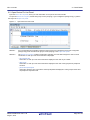
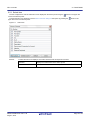
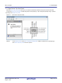
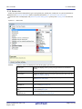
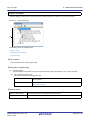
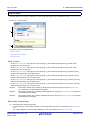
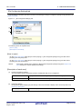
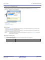
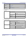
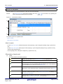
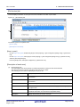
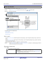
User’s Manual
CS+ V3.00.00
Integrated Development Environment
User’s Manual: RL78 Pin Configurator
Target Device
RL78 Family
All information contained in these materials, including products and product specifications
represents information on the product at the time of publication and is subject to change by
Renesas Electronics Corp. without notice. Please review the latest information published by
Renesas Electronics Corp. through various means, including the Renesas Electronics Corp.
website (http://www.renesas.com).
www.renesas.com
Rev.1.00
2014.08
Notice
1.
Descriptions of circuits, software and other related information in this document are provided only to illustrate the operation of
semiconductor products and application examples. You are fully responsible for the incorporation of these circuits, software,
and information in the design of your equipment. Renesas Electronics assumes no responsibility for any losses incurred by you
or third parties arising from the use of these circuits, software, or information.
2.
Renesas Electronics has used reasonable care in preparing the information included in this document, but Renesas Electronics
does not warrant that such information is error free. Renesas Electronics assumes no liability whatsoever for any damages
incurred by you resulting from errors in or omissions from the information included herein.
3.
Renesas Electronics does not assume any liability for infringement of patents, copyrights, or other intellectual property rights of
third parties by or arising from the use of Renesas Electronics products or technical information described in this document. No
license, express, implied or otherwise, is granted hereby under any patents, copyrights or other intellectual property rights of
Renesas Electronics or others.
4.
You should not alter, modify, copy, or otherwise misappropriate any Renesas Electronics product, whether in whole or in part.
Renesas Electronics assumes no responsibility for any losses incurred by you or third parties arising from such alteration,
modification, copy or otherwise misappropriation of Renesas Electronics product.
5.
Renesas Electronics products are classified according to the following two quality grades: “Standard” and “High Quality”. The
recommended applications for each Renesas Electronics product depends on the product’s quality grade, as indicated below.
“Standard”:
Computers; office equipment; communications equipment; test and measurement equipment; audio and visual
equipment; home electronic appliances; machine tools; personal electronic equipment; and industrial robots etc.
“High Quality”: Transportation equipment (automobiles, trains, ships, etc.); traffic control systems; anti-disaster systems; anticrime systems; and safety equipment etc.
Renesas Electronics products are neither intended nor authorized for use in products or systems that may pose a direct threat to
human life or bodily injury (artificial life support devices or systems, surgical implantations etc.), or may cause serious property
damages (nuclear reactor control systems, military equipment etc.). You must check the quality grade of each Renesas
Electronics product before using it in a particular application. You may not use any Renesas Electronics product for any
application for which it is not intended. Renesas Electronics shall not be in any way liable for any damages or losses incurred
by you or third parties arising from the use of any Renesas Electronics product for which the product is not intended by Renesas
Electronics.
6.
You should use the Renesas Electronics products described in this document within the range specified by Renesas Electronics,
especially with respect to the maximum rating, operating supply voltage range, movement power voltage range, heat radiation
characteristics, installation and other product characteristics. Renesas Electronics shall have no liability for malfunctions or
damages arising out of the use of Renesas Electronics products beyond such specified ranges.
7.
Although Renesas Electronics endeavors to improve the quality and reliability of its products, semiconductor products have
specific characteristics such as the occurrence of failure at a certain rate and malfunctions under certain use conditions. Further,
Renesas Electronics products are not subject to radiation resistance design. Please be sure to implement safety measures to
guard them against the possibility of physical injury, and injury or damage caused by fire in the event of the failure of a Renesas
Electronics product, such as safety design for hardware and software including but not limited to redundancy, fire control and
malfunction prevention, appropriate treatment for aging degradation or any other appropriate measures. Because the evaluation
of microcomputer software alone is very difficult, please evaluate the safety of the final products or systems manufactured by
you.
8.
Please contact a Renesas Electronics sales office for details as to environmental matters such as the environmental compatibility
of each Renesas Electronics product. Please use Renesas Electronics products in compliance with all applicable laws and
regulations that regulate the inclusion or use of controlled substances, including without limitation, the EU RoHS Directive.
Renesas Electronics assumes no liability for damages or losses occurring as a result of your noncompliance with applicable laws
and regulations.
9.
Renesas Electronics products and technology may not be used for or incorporated into any products or systems whose
manufacture, use, or sale is prohibited under any applicable domestic or foreign laws or regulations. You should not use
Renesas Electronics products or technology described in this document for any purpose relating to military applications or use
by the military, including but not limited to the development of weapons of mass destruction. When exporting the Renesas
Electronics products or technology described in this document, you should comply with the applicable export control laws and
regulations and follow the procedures required by such laws and regulations.
10. It is the responsibility of the buyer or distributor of Renesas Electronics products, who distributes, disposes of, or otherwise
places the product with a third party, to notify such third party in advance of the contents and conditions set forth in this
document, Renesas Electronics assumes no responsibility for any losses incurred by you or third parties as a result of
unauthorized use of Renesas Electronics products.
11. This document may not be reproduced or duplicated in any form, in whole or in part, without prior written consent of Renesas
Electronics.
12. Please contact a Renesas Electronics sales office if you have any questions regarding the information contained in this document
or Renesas Electronics products, or if you have any other inquiries.
(Note 1) “Renesas Electronics” as used in this document means Renesas Electronics Corporation and also includes its majorityowned subsidiaries.
(Note 2) “Renesas Electronics product(s)” means any product developed or manufactured by or for Renesas Electronics.
(2012.4)
How to Use This Manual
This manual describes the role of the CS+ integrated development environment for developing applications and systems for RL78 family, and provides an outline of its features.
CS+ is an integrated development environment (IDE) for RL78 family, integrating the necessary tools for the development phase of software (e.g. design, implementation, and debugging) into a single platform.
By providing an integrated environment, it is possible to perform all development using just this product, without the
need to use many different tools separately.
Readers
This manual is intended for users who wish to understand the functions of the CS+ and
design software and hardware application systems.
Purpose
This manual is intended to give users an understanding of the functions of the CS+ to use
for reference in developing the hardware or software of systems using these devices.
Organization
This manual can be broadly divided into the following units.
1.GENERAL
2.FUNCTIONS
A.WINDOW REFERENCE
How to Read This Manual
It is assumed that the readers of this manual have general knowledge of electricity, logic
circuits, and microcontrollers.
Conventions
Data significance:
Active low representation:
Note:
Caution:
Remark:
Numeric representation:
Higher digits on the left and lower digits on the right
XXX (overscore over pin or signal name)
Footnote for item marked with Note in the text
Information requiring particular attention
Supplementary information
Decimal ... XXXX
Hexadecimal ... 0xXXXX
All trademarks or registered trademarks in this document are the property of their respective owners.
TABLE OF CONTENTS
1.
GENERAL . . . . . . . . . . . . . . . . . . . . . . . . . . . . . . . . . . . . . . . . . . . . . . . . . . . . . . . . 6
1.1
Overview . . . . . . . . . . . . . . . . . . . . . . . . . . . . . . . . . . . . . . . . . . . . . . . . . . . . . . . . . . . . . . . . . . . . . . . . . . . . . . 6
1.2
Features. . . . . . . . . . . . . . . . . . . . . . . . . . . . . . . . . . . . . . . . . . . . . . . . . . . . . . . . . . . . . . . . . . . . . . . . . . . . . . . 6
2.
FUNCTIONS. . . . . . . . . . . . . . . . . . . . . . . . . . . . . . . . . . . . . . . . . . . . . . . . . . . . . . . 7
2.1
Overview . . . . . . . . . . . . . . . . . . . . . . . . . . . . . . . . . . . . . . . . . . . . . . . . . . . . . . . . . . . . . . . . . . . . . . . . . . . . . . 7
2.2
Open Device Pin List Panel . . . . . . . . . . . . . . . . . . . . . . . . . . . . . . . . . . . . . . . . . . . . . . . . . . . . . . . . . . . . . . . . 8
2.2.1
Select item . . . . . . . . . . . . . . . . . . . . . . . . . . . . . . . . . . . . . . . . . . . . . . . . . . . . . . . . . . . . . . . . . . . . . . . . . 9
2.2.2
Change display order . . . . . . . . . . . . . . . . . . . . . . . . . . . . . . . . . . . . . . . . . . . . . . . . . . . . . . . . . . . . . . . . 10
2.2.3
Add column. . . . . . . . . . . . . . . . . . . . . . . . . . . . . . . . . . . . . . . . . . . . . . . . . . . . . . . . . . . . . . . . . . . . . . . . 11
2.2.4
Delete column. . . . . . . . . . . . . . . . . . . . . . . . . . . . . . . . . . . . . . . . . . . . . . . . . . . . . . . . . . . . . . . . . . . . . . 11
2.3
Open Device Top View Panel . . . . . . . . . . . . . . . . . . . . . . . . . . . . . . . . . . . . . . . . . . . . . . . . . . . . . . . . . . . . . 12
2.3.1
Select shape of microcontroller . . . . . . . . . . . . . . . . . . . . . . . . . . . . . . . . . . . . . . . . . . . . . . . . . . . . . . . . 13
2.3.2
Select color . . . . . . . . . . . . . . . . . . . . . . . . . . . . . . . . . . . . . . . . . . . . . . . . . . . . . . . . . . . . . . . . . . . . . . . . 14
2.3.3
Select popup information . . . . . . . . . . . . . . . . . . . . . . . . . . . . . . . . . . . . . . . . . . . . . . . . . . . . . . . . . . . . . 15
2.3.4
Select additional information. . . . . . . . . . . . . . . . . . . . . . . . . . . . . . . . . . . . . . . . . . . . . . . . . . . . . . . . . . . 16
2.4
Enter Information . . . . . . . . . . . . . . . . . . . . . . . . . . . . . . . . . . . . . . . . . . . . . . . . . . . . . . . . . . . . . . . . . . . . . . . 17
2.5
Output Report Files . . . . . . . . . . . . . . . . . . . . . . . . . . . . . . . . . . . . . . . . . . . . . . . . . . . . . . . . . . . . . . . . . . . . . 18
2.5.1
Output device pin list . . . . . . . . . . . . . . . . . . . . . . . . . . . . . . . . . . . . . . . . . . . . . . . . . . . . . . . . . . . . . . . . 18
2.5.2
Output device top view . . . . . . . . . . . . . . . . . . . . . . . . . . . . . . . . . . . . . . . . . . . . . . . . . . . . . . . . . . . . . . . 19
A.
WINDOW REFERENCE. . . . . . . . . . . . . . . . . . . . . . . . . . . . . . . . . . . . . . . . . . . . . 20
A.1
Overview . . . . . . . . . . . . . . . . . . . . . . . . . . . . . . . . . . . . . . . . . . . . . . . . . . . . . . . . . . . . . . . . . . . . . . . . . . . . . 20
Main window . . . . . . . . . . . . . . . . . . . . . . . . . . . . . . . . . . . . . . . . . . . . . . . . . . . . . . . . . . . . . . . . . . . . . . . . . . . . . . . . 21
Project Tree panel . . . . . . . . . . . . . . . . . . . . . . . . . . . . . . . . . . . . . . . . . . . . . . . . . . . . . . . . . . . . . . . . . . . . . . . . . . . 24
Property panel . . . . . . . . . . . . . . . . . . . . . . . . . . . . . . . . . . . . . . . . . . . . . . . . . . . . . . . . . . . . . . . . . . . . . . . . . . . . . . 25
[Pin Configurator Settings] tab . . . . . . . . . . . . . . . . . . . . . . . . . . . . . . . . . . . . . . . . . . . . . . . . . . . . . . . . . . . . . . . . 27
[Device Pin List Information] tab . . . . . . . . . . . . . . . . . . . . . . . . . . . . . . . . . . . . . . . . . . . . . . . . . . . . . . . . . . . . . . . 28
[Device Top View Settings] tab . . . . . . . . . . . . . . . . . . . . . . . . . . . . . . . . . . . . . . . . . . . . . . . . . . . . . . . . . . . . . . . . 29
Device Pin List panel . . . . . . . . . . . . . . . . . . . . . . . . . . . . . . . . . . . . . . . . . . . . . . . . . . . . . . . . . . . . . . . . . . . . . . . . . 31
[Pin Number] tab . . . . . . . . . . . . . . . . . . . . . . . . . . . . . . . . . . . . . . . . . . . . . . . . . . . . . . . . . . . . . . . . . . . . . . . . . . . 33
[Macro] tab . . . . . . . . . . . . . . . . . . . . . . . . . . . . . . . . . . . . . . . . . . . . . . . . . . . . . . . . . . . . . . . . . . . . . . . . . . . . . . . 35
[External Peripheral] tab . . . . . . . . . . . . . . . . . . . . . . . . . . . . . . . . . . . . . . . . . . . . . . . . . . . . . . . . . . . . . . . . . . . . . 37
Device Top View panel . . . . . . . . . . . . . . . . . . . . . . . . . . . . . . . . . . . . . . . . . . . . . . . . . . . . . . . . . . . . . . . . . . . . . . . . 39
Output panel . . . . . . . . . . . . . . . . . . . . . . . . . . . . . . . . . . . . . . . . . . . . . . . . . . . . . . . . . . . . . . . . . . . . . . . . . . . . . . . . 41
Column Chooser dialog box . . . . . . . . . . . . . . . . . . . . . . . . . . . . . . . . . . . . . . . . . . . . . . . . . . . . . . . . . . . . . . . . . . . . 42
New Column dialog box . . . . . . . . . . . . . . . . . . . . . . . . . . . . . . . . . . . . . . . . . . . . . . . . . . . . . . . . . . . . . . . . . . . . . . . 44
Save As dialog box . . . . . . . . . . . . . . . . . . . . . . . . . . . . . . . . . . . . . . . . . . . . . . . . . . . . . . . . . . . . . . . . . . . . . . . . . . . 45
Revision Record . . . . . . . . . . . . . . . . . . . . . . . . . . . . . . . . . . . . . . . . . . . . . . . . . . . . . . . . 46
CS+ V3.00.00
1. GENERAL
1. GENERAL
CS+ is an integrated development environment used to carry out tasks such as design, coding, build and debug for
developing application systems.
This chapter gives an overview of the Pin Configurator.
1.1 Overview
The Pin Configurator, which is one of the components provided by CS+, enables you to output the pin assignment of the
microcontroller (device pin list and device top view) by configuring various information using the GUI.
1.2 Features
The Pin Configurator has the following features.
(1)
Reporting function
You can output configured information using the Pin Configurator as files in various formats for use as design
documents.
R20UT3106EJ0100 Rev.1.00
Aug 01, 2014
Page 6 of 49
CS+ V3.00.00
2. FUNCTIONS
2. FUNCTIONS
This chapter describes the key functions provided by the Pin Configurator along with operation procedures.
Remark
In this chapter, an example where an RL78/G13 (ROM: 16KB) R5F1006A(20pin) is the target device is
used to explain the key functions.
2.1 Overview
The Pin Configurator is used to output report files such as a device pin list and a device top view by entering pin assignment information of the microcontroller.
The following sections describe the operation procedures for Pin Configurator.
(1)
Start CS+
Launch CS+ from the [Start] menu of Windows.
(2)
Create/Open project
Create a new project (that defines a kind of project, microcontroller to be used, build tools to be used, etc.) or load
an existing project.
(3)
Open Device Pin List Panel
Open the Device Pin List panel, where you enter information on the pins of the microcontroller.
(a)
Select item
Allows you to select items displayed in the device pin list.
(b)
Change display order
Allows you to change the order in which items are displayed in the device pin list.
(c)
Add column
Allows you to add columns to the device pin list.
(d)
Delete column
Allows you to delete columns from the device pin list.
(4)
Open Device Top View Panel
Open the Device Top View panel, where you can confirm the information entered for the pins.
(a)
Select shape of microcontroller
Allows you to select the shape of the microcontroller displayed in the Device Top View panel.
(b)
Select color
Allows you to select colors used to distinguish the type of pins (power pins, special pins, used pins, etc.) whose
information is displayed in the Device Top View panel.
(c)
Select popup information
Allows you to select the type of information that popups when you move the mouse cursor over each pin in the
Device Top View panel.
(d)
Select additional information
Select the type of information to display in Pin area of the Device Top View panel.
(5)
Enter Information
Enter information on the pins of the microcontroller in the Device Pin List panel.
(6)
Output Report Files
Output report files (files containing configured information using Pin Configurator: device pin list and device top
view) to the specified folder.
(a)
Output device pin list
Output a device pin list.
(b)
Output device top view
Output a device top view.
(7)
Save project
Save a project.
R20UT3106EJ0100 Rev.1.00
Aug 01, 2014
Page 7 of 49
CS+ V3.00.00
2. FUNCTIONS
2.2 Open Device Pin List Panel
Open the Device Pin List panel, where you enter information on the pins of the microcontroller.
To open the Device Pin List panel, double-click [Project name (Project)] >> [Pin Configurator (Design Tool)] >> [Device
Pin List] in the Project Tree panel.
Figure 2.1
Open Device Pin List Panel
Remark 1.
If an unsupported microcontroller is defined in the project for Pin Configurator, then "[Pin Configurator
(Design Tool)] node" will hide under [Project name (Project)] in the Project Tree panel.
Remark 2.
The Device Pin List panel consists of three tabs. Selecting one of the tabs changes the order in which
"information on each pin of the microcontroller" is displayed.
- [Pin Number] tab
Information on each pin of the microcontroller is displayed in the order of pin number.
- [Macro] tab
Information on each pin of the microcontroller is displayed in the order it was grouped into peripheral
functions.
- [External Peripheral] tab
Information about the pins connected to external peripherals is displayed in order grouped at the external-peripheral component level.
R20UT3106EJ0100 Rev.1.00
Aug 01, 2014
Page 8 of 49
CS+ V3.00.00
2. FUNCTIONS
2.2.1 Select item
The Pin Configurator is used to select items to be displayed in the device pin list using the
button in the upper left
corner of the device pin list.
To select the item to be displayed, use the Column Chooser dialog box that opens by pressing the
button in the
upper left corner of the device pin list.
Figure 2.2
Remark
Select Item
To select the item to be displayed, check the check box that corresponds to the item.
Checked
Displays the selected item in the device pin list.
Not checked
Hides the selected item in the device pin list.
R20UT3106EJ0100 Rev.1.00
Aug 01, 2014
Page 9 of 49
CS+ V3.00.00
2. FUNCTIONS
2.2.2 Change display order
In Pin Configurator, you can change the display order of columns in the device pin list (move columns) by dragging and
dropping columns.
Figure 2.3
Remark
Change Display Order
To change the display order, click the
button in the upper left of the device pin list. The Column
Chooser dialog box opens. Drag an item displayed in the dialog's select Items to display area, and drop it
to the desired destination in the device pin list. This will change the display order.
R20UT3106EJ0100 Rev.1.00
Aug 01, 2014
Page 10 of 49
CS+ V3.00.00
2. FUNCTIONS
2.2.3 Add column
The Pin Configurator is used to add the "user's own column" to the device pin list using the [New Column...] button in the
Column Chooser dialog box that opens by pressing the
button in the upper left corner of the device pin list.
To add a column, use the New Column dialog box that opens by pressing the [New Column...] button in the Column
Chooser dialog box.
Figure 2.4
Remark
Add Column
On the device pin list, adding columns to the first level of [Macro] tab, [External Peripheral] tab is
restricted.
2.2.4 Delete column
The Pin Configurator is used to delete the "user's own column" from the device pin list using the [Delete Column] button
in the Column Chooser dialog box that opens by pressing the
button in the upper left corner of the device pin list.
To delete a column, select the column you want to delete in the displayed item selection area of the Column Chooser
dialog box, and press the [Delete Column] button.
Figure 2.5
Remark
Delete Column
You can only delete the column which you added using the New Column dialog box.
R20UT3106EJ0100 Rev.1.00
Aug 01, 2014
Page 11 of 49
CS+ V3.00.00
2. FUNCTIONS
2.3 Open Device Top View Panel
Open the Device Top View panel, where you can confirm the information entered for the pins of the microcontroller.
To open the Device Top View panel, double-click [Project name (Project)] >> [Pin Configurator (Design Tool)] >> [Device
Top View] in the Project Tree panel.
Figure 2.6
Remark
Open Device Top View Panel
In the Property panel, on the [Pin Configurator Settings] tab, if "BGA" is selected for the Package type,
then Device Top View panel cannot be opened.
R20UT3106EJ0100 Rev.1.00
Aug 01, 2014
Page 12 of 49
CS+ V3.00.00
2. FUNCTIONS
2.3.1 Select shape of microcontroller
Select the shape of the microcontroller displayed in the Device Top View panel which is opened as described in "2.3
Open Device Top View Panel".
To select the shape of the microcontroller, click [Pin Configurator Settings] tab >> [Package] >> [Package type] in the
Property panel and select the desired shape.
Figure 2.7
Remark
Select Shape of Microcontroller
Selection of the shape of the microcontroller is made using the order name (such as GC and GF).
R20UT3106EJ0100 Rev.1.00
Aug 01, 2014
Page 13 of 49
CS+ V3.00.00
2. FUNCTIONS
2.3.2 Select color
Select the colors used to distinguish the type of pins (power pins, special pins, unused pins, etc.) whose information is
displayed in the Device Top View panel which is opened as described in “2.3 Open Device Top View Panel”.
To select the color to be displayed, click [Device Top View Settings] tab >> [Color] in the Property panel and select the
color.
Figure 2.8
Remark
Select Color
Select the colors to be displayed for the following eight types of items.
Power pins
Selects the display color for power pins (pins whose use is limited to
power).
Special pins
Selects the display color for special pins (pins with specified uses).
Unused pins
Selects the display color for unused pins (dual-use pins with no use set
in the Device Pin List panel).
Used pins
Selects the display color for used pins (dual-use pins with a use set in
the Device Pin List panel).
Device
Selects the display color of the microcontroller.
Highlight color for a
selected pin
Selects the background color of a pin selected in the Device Pin List
panel, on the [Pin Number] tab.
Highlight color for macro
pins
Selects the background color of pins selected in the Device Pin List
panel, on the [Macro] tab.
Highlight color for external
peripheral pins
Selects the background color of pins selected in the Device Pin List
panel, on the [External Peripheral] tab.
R20UT3106EJ0100 Rev.1.00
Aug 01, 2014
Page 14 of 49
CS+ V3.00.00
2. FUNCTIONS
2.3.3 Select popup information
Select the type of information that popups when you move the mouse cursor over each pin in the Device Top View panel
which is opened as described in “2.3 Open Device Top View Panel”.
To select the popup information, click [Device Top View Settings] tab >> [Tool Tip] >> [Tool tip] in the Property panel and
select the desired type of information.
Figure 2.9
Remark
Select Popup Information
Popup information is selected from the following four types.
Display all
Displays the “Description”, “Recommend Connection for Unused”, and
“Attention” strings for the device pin list.
Description / recommended connection for
unused pin only
Displays the "Description", and "Recommend Connection for Unused"
strings for the device pin list.
Attention only
Displays the “Attention” string for the device pin list.
Not display
Hides tooltips when the mouse cursor hovers over a pin.
R20UT3106EJ0100 Rev.1.00
Aug 01, 2014
Page 15 of 49
CS+ V3.00.00
2. FUNCTIONS
2.3.4 Select additional information
Select the type of information to display in Pin area, in the Device Top View panel opened in “2.3 Open Device Top View
Panel”.
Note that additional information is selected from the Property panel, on the [Device Top View Settings] tab, by selecting
the corresponding information under [Pin Name Display].
Figure 2.10 Select Additional Information
Remark 1.
Remark 2.
Select one of the following two types for Define name (whether to display the “Define Name” string of the
Device Pin List in appended format).
Display
Displays the "Define Name" string of the device pin list in appended
format.
Not display
Hides the “Define Name” string of the device pin list.
Select one of the following two types for Pin function (whether to display it whether or not a function is
selected for “Function” on the Device Pin List).
Display all
Displays functions selected via the device pin list's "Function" feature in
parentheses.
Selected function only
Only display functions selected via the device pin list's “Function” feature
in the device top view.
R20UT3106EJ0100 Rev.1.00
Aug 01, 2014
Page 16 of 49
CS+ V3.00.00
2. FUNCTIONS
2.4 Enter Information
Enter information on the pins of the microcontroller in the Device Pin List panel which is opened as described in “2.2
Open Device Pin List Panel”.
Remark 1.
You cannot add information in the “Pin Number” column, “Pin Name” column, “Description” column, “Recommend Connection for Unused” column and “Attention” column because they contain fixed information.
Remark 2.
If the “Free” in the “Function” column is changed to a specific pin name, color of the corresponding pin in
the Device Top View panel changes from the “color representing the unused pins” to the “color representing the used pins” selected by clicking [Device Top View Settings] tab >> [Color] in the Property panel.
Figure 2.11
Change in Displayed Color
R20UT3106EJ0100 Rev.1.00
Aug 01, 2014
Page 17 of 49
CS+ V3.00.00
2. FUNCTIONS
2.5 Output Report Files
Output report files (files containing information configured using Pin Configurator: device pin list and device top view) to
the specified folder.
2.5.1 Output device pin list
Select [File] menu >> [Save Pin List As...] to output a report file (a file containing information configured using Pin Configurator: device pin list).
The destination folder for the device pin list is specified in the Save As dialog box which opens by selecting [File] menu
>> [Save Pin List As ...].
Figure 2.12 Output Device Pin List
Remark 1.
If a device pin list has been already output, that list will be overwritten by selecting [File] menu >> [Save
Pin List].
Remark 2.
The output format for the device pin list is limited to Microsoft Office Excel Book.
R20UT3106EJ0100 Rev.1.00
Aug 01, 2014
Page 18 of 49
CS+ V3.00.00
2. FUNCTIONS
2.5.2 Output device top view
Select [File] menu >> [Save Top View As...] to output a report file (a file containing information configured using Pin Configurator: device top view).
The destination folder for the device top view is specified in the Save As dialog box which opens by selecting [File]
menu >> [Save Top View As ...].
Figure 2.13 Output Device Top View
Remark
If a device top view has been already output, that view will be overwritten by selecting [File] menu >>
[Save Top View].
R20UT3106EJ0100 Rev.1.00
Aug 01, 2014
Page 19 of 49
CS+ V3.00.00
A. WINDOW REFERENCE
A. WINDOW REFERENCE
This appendix explains in detail the functions of the windows, panels and dialog boxes of the Pin Configurator.
A.1 Overview
The Pin Configurator has the following windows, panels and dialog boxes.
Table A.1
Window/Panel/Dialog Box List
Window/Panel/Dialog Box Name
Function
Main window
This is the first window to open when CS+ is launched. This window is used
to operate various components (design tool, build tool, etc.) provided by
CS+.
Project Tree panel
This panel displays the components of the project (microcontroller, design
tool, build tool, etc.) in a tree structure.
Property panel
This panel allows you to view the information on and change the setting for
the node selected in the Project Tree panel.
Device Pin List panel
This panel allows you to enter information on each pin of the
microcontroller.
Device Top View panel
This panel displays the information entered in the Device Pin List panel.
Output panel
This panel displays operation logs for various components (design tool,
build tool, etc.) provided by CS+.
Column Chooser dialog box
This dialog box allows you to choose whether or not to display the item
listed in this dialog box in the device pin list, and add columns to or delete
columns from the device pin list.
New Column dialog box
This dialog box allows you to add your own column to the device pin list.
Save As dialog box
This dialog box allows you to name and save a file.
R20UT3106EJ0100 Rev.1.00
Aug 01, 2014
Page 20 of 49
CS+ V3.00.00
A. WINDOWS REFERENCE
Main window
This is the first window to open when CS+ is launched. This window is used to operate various components (design tool,
build tool, etc.) provided by CS+.
Figure A.1
Main WIndow
(1)
(2)
The following items are explained here.
- [How to open]
- [Description of each area]
[How to open]
- From the [start] menu, select [All Programs] >> [Renesas Electronics CS+] >>[CS+].
[Description of each area]
(1)
(a)
Menu bar
This area consists of the following menu items.
[FIle] menu
Save Pin List
Device Pin List panel-dedicated item
Saves a report file (a file containing information configured using Pin
Configurator: device pin list) overwriting the existing file.
Save Pin List As...
Device Pin List panel-dedicated item
Opens the Save As dialog box for naming and saving a report file (a file
containing information configured using Pin Configurator: device pin list).
R20UT3106EJ0100 Rev.1.00
Aug 01, 2014
Page 21 of 49
CS+ V3.00.00
(b)
(c)
A. WINDOWS REFERENCE
Save Top View
Device Top View panel-dedicated item
Saves a report file (a file containing information configured using Pin
Configurator: device top view) overwriting the existing file.
Save Top View As...
Device Top View panel-dedicated item
Opens the Save As dialog box for naming and saving a report file (a file
containing information configured using Pin Configurator: device top view).
Save Output-Tab Name
Output panel-dedicated item
Saves the message corresponding to the specified tab overwriting the existing
file.
Save Output-Tab Name
As...
Output panel-dedicated item
Opens the Save As dialog box for naming and saving the message corresponding to the specified tab.
[Edit] menu
Undo
Property panel-dedicated item
Cancels the effect of an edit operation to restore the previous state.
Cut
Property panel-dedicated item
Sends the character string or lines selected with range selection to the clipboard and deletes them.
Copy
Property panel/Output panel-dedicated item
Sends the character string or lines selected with range selection to the clipboard.
Paste
Property panel-dedicated item
Inserts the contents of the clipboard at the caret position.
Delete
Property panel-dedicated item
Deletes the character string or the lines selected with the range selection.
Select All
Property panel/Output panel-dedicated item
Selects all the strings displayed in the item being edited or all the strings displayed in the Message area.
Search...
Device Pin List panel/Output panel-dedicated item
Opens the Search and Replace dialog box for searching strings with the [Quick
Search] tab selected.
Replace...
Output panel-dedicated item
Opens the Search and Replace dialog box for replacing strings with the [Whole
Replace] tab selected.
[View] menu
Project Tree
Project Tree panel-dedicated item
Opens the Project Tree panel.
Property
Property panel-dedicated item
Opens the Property panel.
Output
Output panel-dedicated item
Opens the Output panel.
R20UT3106EJ0100 Rev.1.00
Aug 01, 2014
Page 22 of 49
CS+ V3.00.00
Pin Configurator
(d)
(2)
A. WINDOWS REFERENCE
The cascading menu shown below is displayed.
Device Pin List
Device Pin List panel-dedicated item
Opens the Device Pin List panel.
Device Top View
Device Top View panel-dedicated item
Opens the Device Top View panel.
[Help] menu
Open Help for Project Tree
Panel
Project Tree panel-dedicated item
Displays the help of Project Tree panel.
Open Help for Property
Panel
Property panel-dedicated item
Displays the help of Property panel.
Open Help for Device Pin
List Panel
Device Pin List panel-dedicated item
Displays the help of Device Pin List panel.
Open Help for Device Top
View Panel
Device Top View panel-dedicated item
Displays the help of Device Top View panel.
Open Help for Output
Panel
Output panel-dedicated item
Displays the help of Output panel.
Panel display area
This area consists of multiple panels, each dedicated to a different purpose.
See the following sections for details on this area.
- Project Tree panel
- Property panel
- Device Pin List panel
- Device Top View panel
- Output panel
R20UT3106EJ0100 Rev.1.00
Aug 01, 2014
Page 23 of 49
CS+ V3.00.00
A. WINDOWS REFERENCE
Project Tree panel
This panel displays components of the project (microcontroller, design tool, build tool, etc.) in a tree structure.
Figure A.2
Project Tree Panel
(1)
The following items are explained here.
- [How to open]
- [Description of each area]
- [Context menu]
[How to open]
- From the [View] menu, select [Project Tree].
[Description of each area]
(1)
(a)
Project tree area
This area displays components of the project (microcontroller, design tool, build tool, etc.) in a tree structure.
Pin Configurator (Design Tool)
This node consists of the following pin nodes.
Device Pin List
Opens the Device Pin List panel for entering information on the pins of the
microcontroller.
Device Top View
Opens the Device Top View panel that displays the information entered in the
Device Pin List panel.
[Context menu]
Return to Reset Value
The default settings of the selected node are restored.
Property
Opens the Property panel corresponding to the selected node.
R20UT3106EJ0100 Rev.1.00
Aug 01, 2014
Page 24 of 49
CS+ V3.00.00
A. WINDOWS REFERENCE
Property panel
This panel allows you to view the information on and change the setting for the node selected in the Project Tree panel.
Figure A.3
Property Panel
(1)
(2)
The following items are explained here.
- [How to open]
- [Description of each area]
- [Context menu]
[How to open]
- On the Project Tree panel, select [Project name (Project)] >> [Pin Configurator (Design Tool)], and then select
[Property] from the [View] menu.
- On the Project Tree panel, select [Project name (Project)] >> [Pin Configurator (Design Tool)], and then select
[Property] from the context menu.
- On the Project Tree panel, select [Project name (Project)] >> [Pin Configurator (Design Tool)] >> [Device Pin List],
and then select [Property] from the [View] menu.
- On the Project Tree panel, select [Project name (Project)] >> [Pin Configurator (Design Tool)] >> [Device Pin List],
and then select [Property] from the context menu.
- On the Project Tree panel, select [Project name (Project)] >> [Pin Configurator (Design Tool)] >> [Device Top View],
and then select [Property] from the [View] menu.
- On the Project Tree panel, select [Project name (Project)] >> [Pin Configurator (Design Tool)] >> [Device Top View],
and then select [Property] from the context menu.
Remark 1.
If this panel is already open, selecting a different [Pin Configurator (Design Tool)] in the Project Tree
panel changes the content displayed accordingly.
Remark 2.
If this panel is already open, selecting a different [Device Pin List] in the Project Tree panel changes the
content displayed accordingly.
Remark 3.
If this panel is already open, selecting a different [Device Top View] in the Project Tree panel changes the
content displayed accordingly.
[Description of each area]
(1)
Detail information display/change area
This area allows you to view the information on and change the setting for the node selected in the Project Tree
panel.
The content displayed in this area differs depending on the node selected in the Project Tree panel.
R20UT3106EJ0100 Rev.1.00
Aug 01, 2014
Page 25 of 49
CS+ V3.00.00
(2)
A. WINDOWS REFERENCE
Tab selection area
In this panel, following tabs are contained (see the section explaining each tab for details on the display/setting on
the tab).
- [Pin Configurator Settings] tab
- [Device Pin List Information] tab
- [Device Top View Settings] tab
[Context menu]
Undo
Cancels the effect of an edit operation to restore the previous state.
Cut
Sends the character string or lines selected with range selection to the clipboard and
deletes them.
Copy
Sends the character string or lines selected with range selection to the clipboard.
Paste
Inserts the contents of the clipboard at the caret position.
Delete
Deletes the character string or the lines selected with the range selection.
Select All
Selects all strings displayed in the item being edited.
R20UT3106EJ0100 Rev.1.00
Aug 01, 2014
Page 26 of 49
CS+ V3.00.00
A. WINDOWS REFERENCE
[Pin Configurator Settings] tab
This tab displays information (Product Information and Package) on the [Pin Configurator (Design Tool)] selected in the
Project Tree panel.
Figure A.4
[Pin Configurator Settings] Tab
(1)
(2)
The following items are explained here.
- [How to open]
- [Description of each area]
[How to open]
- On the Project Tree panel, select [Project name (Project)] >> [Pin Configurator (Design Tool)], and then select
[Property] from the [View] menu.
- On the Project Tree panel, select [Project name (Project)] >> [Pin Configurator (Design Tool)], and then select
[Property] from the context menu.
Remark
If this panel is already open, selecting a different [Pin Configurator (Design Tool)] in the Project Tree
panel changes the content displayed accordingly.
[Description of each area]
(1)
(2)
[Product Information] category
This area displays product information (Version and Release date) on Pin Configurator.
Version
Displays the version of Pin Configurator (Pin Configurator Plug-in).
Release date
Displays the release date of Pin Configurator (Pin Configurator Plug-in).
[Package] category
Change the shape (Package type) and settings of the microcontroller to display as the device top view in the
Device Top View panel.
Package type
R20UT3106EJ0100 Rev.1.00
Aug 01, 2014
Selects the shape of the microcontroller displayed in the device top view.
Page 27 of 49
CS+ V3.00.00
A. WINDOWS REFERENCE
[Device Pin List Information] tab
This tab displays information (Product Information) on the [Device Pin List] selected in the Project Tree panel.
Figure A.5
[Device Pin List Information] Tab
(1)
The following items are explained here.
- [How to open]
- [Description of each area]
[How to open]
- On the Project Tree panel, select [Project name (Project)] >> [Pin Configurator (Design Tool)] >> [Device Pin List],
and then select [Property] from the [View] menu.
- On the Project Tree panel, select [Project name (Project)] >> [Pin Configurator (Design Tool)] >> [Device Pin List],
and then select [Property] from the context menu.
Remark
If this panel is already open, selecting a different [Device Pin List] in the Project Tree panel changes the
content displayed accordingly.
[Description of each area]
(1)
[Product Information] category
This area displays product information (Version and Release date) on Pin Configurator.
Version
Displays the version of Pin Configurator (Pin Configurator Plug-in).
Release date
Displays the release date of Pin Configurator (Pin Configurator Plug-in).
R20UT3106EJ0100 Rev.1.00
Aug 01, 2014
Page 28 of 49
CS+ V3.00.00
A. WINDOWS REFERENCE
[Device Top View Settings] tab
This panel allows you to view the information on and change the setting for the node selected in the Project Tree panel.
Figure A.6
[Device Top View Settings] Tab
(1)
(2)
(3)
The following items are explained here.
- [How to open]
- [Description of each area]
[How to open]
- On the Project Tree panel, select [Project name (Project)] >> [Pin Configurator (Design Tool)] >> [Device Top View],
and then select [Property] from the [View] menu.
- On the Project Tree panel, select [Project name (Project)] >> [Pin Configurator (Design Tool)] >> [Device Top View],
and then select [Property] from the context menu.
Remark
If this panel is already open, selecting a different [Device Top View] in the Project Tree panel changes the
content displayed accordingly.
[Description of each area]
(1)
[Color] category
Select the display colors to differentiate the pin groups (Power pins, Special pins, etc.) in the device top view.
Power pins
Selects the display color for power pins (pins whose use is limited to power).
Special pins
Selects the display color for special pins (pins with specified uses).
Unused pins
Selects the display color for unused pins (dual-use pins with no use set in the
Device Pin List panel).
Used pins
Selects the display color for used pins (dual-use pins with a use set in the Device
Pin List panel).
R20UT3106EJ0100 Rev.1.00
Aug 01, 2014
Page 29 of 49
CS+ V3.00.00
(2)
Device
Selects the display color of the microcontroller.
Highlight color for a
selected pin
Selects the background color of a pin selected in the Device Pin List panel, on the
[Pin Number] tab.
Highlight color for macro
pins
Selects the background color of pins selected in the Device Pin List panel, on the
[Macro] tab.
Highlight color for external
peripheral pins
Selects the background color of pins selected in the Device Pin List panel, on the
[External Peripheral] tab.
[Tool Tip] category
Select whether to display a tooltip with information about a pin when the mouse cursor is moved over the pin in the
device top view.
Tooltip
(3)
A. WINDOWS REFERENCE
Selects whether to display a tooltip with information about a pin when the mouse
cursor is moved over the pin.
Display all
Displays the "Description", "Recommend Connection for Unused", and "Attention" strings for the
device pin list.
Description / recommended connection for
unused pin only
Displays the "Description", and "Recommend
Connection for Unused" strings for the device pin
list.
Attention only
Displays the "Attention" string for the device pin list.
Not display
Hides tooltips when the mouse cursor hovers over
a pin.
[Pin Name Display] category
Select whether to display additional information about the pin in the device top view.
Define name
Pin function
R20UT3106EJ0100 Rev.1.00
Aug 01, 2014
Selects whether to display the "Define Name" string of the device pin list
appended to the pin in the device top view.
Display
Displays the "Define Name" string of the device pin
list in appended format.
Not display
Hides the "Define Name" string of the device pin
list.
Selects whether to also display unselected functions in the device top view when
a function has been selected from the device pin list's "Function" feature.
Display all
Displays functions selected via the device pin list's
"Function" feature in parentheses.
Selected function only
Only display functions selected via the device pin
list's "Function" feature in the device top view.
Page 30 of 49
CS+ V3.00.00
A. WINDOWS REFERENCE
Device Pin List panel
This panel allows you to enter information on each pin of the microcontroller.
Remark
Figure A.7
The Device pin list area area can be zoomed in and out by
mouse wheel while holding down the [Ctrl] key.
in the tool bar, or by operating the
Device Pin List Panel
(1)
(2)
(3)
The following items are explained here.
- [How to open]
- [Description of each area]
[How to open]
- On the Project Tree panel, double-click [Project name (Project)] >> [Pin Configurator (Design Tool)] >> [Device Pin
List].
- On the Project Tree panel, select [Project name (Project)] >> [Pin Configurator (Design Tool)] >> [Device Pin List],
and then press the [Enter] key.
- From the [View] menu, select [Pin Configurator] >> [Device Pin List].
[Description of each area]
(1)
Toolbar
This area consists of the following buttons.
Displays the information in the Device pin list area in an expanded view.
Displays the information in the Device pin list area in a folded view only.
Clicks this button to automatically process the configuration information in the
selected function, I/O, N-ch, and other fields after selecting one of the peripheral
functions displayed in the first level on the [Macro] tab.
Clicks this button to initialize the selected function, I/O, N-ch, and other fields after
selecting one of the peripheral functions displayed in the first level on the [Macro]
tab.
Clicks this button to create an external peripheral controller from the external
peripheral controller information on the [External Peripheral] tab, and display it in
the Device Top View panel.
Clicks this button to delete the information for the external peripheral controller
displayed on the [External Peripheral] tab, on the first layer.
R20UT3106EJ0100 Rev.1.00
Aug 01, 2014
Page 31 of 49
CS+ V3.00.00
A. WINDOWS REFERENCE
Remark 1.
Click the
button to add the information in question as a choice in the "External Parts" column of
the [Macro] tab and the [Pin Number] tab.
Remark 2.
Click the
button to remove the external peripheral component in question from the Device top
view area if the Device Top View panel.
(2)
Device pin list area
This area displays the "device pin list" for entering information on the pins of the microcontroller.
(3)
Tab selection area
Selecting the tab changes the order in which "information on each pin of the microcontroller" is displayed.
This panel has the following tabs:
- [Pin Number] tab
This tab displays information on each pin of the microcontroller in the order of pin number.
- [Macro] tab
This tab displays information on each pin of the microcontroller in the order it was grouped into peripheral functions.
- [External Peripheral] tab
This tab displays information about the pins connected to external peripherals in order grouped at the externalperipheral component level.
R20UT3106EJ0100 Rev.1.00
Aug 01, 2014
Page 32 of 49
CS+ V3.00.00
A. WINDOWS REFERENCE
[Pin Number] tab
This tab displays information on each pin of the microcontroller in the order of pin number.
Figure A.8
[Pin Number] Tab
(1)
The following items are explained here.
- [How to open]
- [Description of each area]
[How to open]
- On the Project Tree panel, double-click [Project name (Project)] >> [Pin Configurator (Design Tool)] >> [Device Pin
List].
- On the Project Tree panel, select [Project name (Project)] >> [Pin Configurator (Design Tool)] >> [Device Pin List],
and then press the [Enter] key.
- From the [View] menu, select [Pin Configurator] >> [Device Pin List].
[Description of each area]
(1)
Device pin list area
This area displays the “device pin list” for entering information on the pins of the microcontroller.
The device pin list in this area is organized in the order of pin number.
The following are the columns comprising the device pin list.
Pin Number
Displays the pin number of the pin.
Pin Name
This area allows you to select “which function to use” when the pin has more than
one functions.
Function
This area allows you to select “which function to use” when the pin has more than
one functions.
I/O
This area allows you to select the I/O mode of the pin.
N-ch
This area allows you to select “which output mode to apply” when using the pin in
the output mode.
Define Name
This area allows you to assign a “user-defined pin name” to the pin.
wITHIN 256 characters can be entered in the [Define Name].
Description
Displays the summary of function of the pin.
R20UT3106EJ0100 Rev.1.00
Aug 01, 2014
Page 33 of 49
CS+ V3.00.00
A. WINDOWS REFERENCE
Recommend Connection
for Unused
Displays instructions on how to handle the pin when it is not used.
This column displays information only when the “Free” is selected in the “Function” column.
Attention
Displays the precaution on using the pin.
External Parts
This area is for selecting which external peripheral controller to connect the pin to.
Remark 1.
You cannot add information in the “Pin Number” column, “Pin Name” column, “Description” column,
“Recommend Connection for Unused” column and “Attention” column because they contain fixed
information.
Remark 2.
If the “Free” in the “Function” column is changed to a specific pin name, color of the corresponding
pin in the Device Top View panel changes from the “color representing the unused pins” to the
“color representing the used pins” selected by clicking [Device Top View Settings] tab >> [Color] in
the Property panel.
Remark 3.
To move columns (change the display order) in the device pin list, drag and drop the desired column to the desired location.
Remark 4.
To add the “user's own column”, use the New Column dialog box which opens by pressing the [New
Column...] button in the Column Chooser dialog box which opens by pressing the
button in the
upper left corner of the device pin list.
R20UT3106EJ0100 Rev.1.00
Aug 01, 2014
Page 34 of 49
CS+ V3.00.00
A. WINDOWS REFERENCE
[Macro] tab
This tab displays information on each pin of the microcontroller in the order it was grouped into peripheral functions.
Figure A.9
[Macro] Tab
(1)
The following items are explained here.
- [How to open]
- [Description of each area]
[How to open]
- On the Project Tree panel, double-click [Project name (Project)] >> [Pin Configurator (Design Tool)] >> [Device Pin
List].
- On the Project Tree panel, select [Project name (Project)] >> [Pin Configurator (Design Tool)] >> [Device Pin List],
and then press the [Enter] key.
- From the [View] menu, select [Pin Configurator] >> [Device Pin List].
[Description of each area]
(1)
(a)
(a)
Device pin list area
This area displays the “device pin list” for entering information on the pins of the microcontroller.
The device pin list in this area is organized in the order the pins were grouped into peripheral functions.
First layer
The following are the columns comprising the device pin list.
Macro Name
Displays the name of the peripheral function.
Total
Displays the total number of pins assigned to the peripheral function.
Used
Displays the total number of pins for which the purpose has been set.
Used in Other Macro
Displays the total number of pins for which the purpose has been set by other
peripheral functions.
Second layer
The following are the columns comprising the device pin list.
Pin Number
Displays the pin number of the pin.
Pin Name
Displays the pin name of the pin.
R20UT3106EJ0100 Rev.1.00
Aug 01, 2014
Page 35 of 49
CS+ V3.00.00
A. WINDOWS REFERENCE
Function
This area allows you to select “which function to use” when the pin has more
than one functions.
I/O
This area allows you to select the I/O mode of the pin.
N-ch
This area allows you to select “which output mode to apply” when using the pin
in the output mode.
Define Name
This area allows you to assign a “user-defined pin name” to the pin.
Within 256 characters can be entered in the [Define Name].
Description
Displays the summary of function of the pin.
Recommend Connection
for Unused
Displays instructions on how to handle the pin when it is not used.
This column displays information only when the “Free” is selected in the “Function” column.
Attention
Displays the precaution on using the pin.
External Parts
This area is for selecting which external peripheral controller to connect the pin
to.
Remark 1.
You cannot add information in the “Macro Name”, “Total”, “Used”, “Used by other function”, “Pin
Number”, “Pin Name”, “Description”, “Recommend Connection for Unused” and “Attention” columns because they contain fixed information.
Remark 2.
If the “Free” in the “Function” column is changed to a specific pin name, color of the corresponding
pin in the Device Top View panel changes from the “color representing the unused pins” to the
“color representing the used pins” selected by clicking [Device Top View Settings] tab >> [Color] in
the Property panel.
Remark 3.
To move columns (change the display order) in the device pin list, drag and drop the desired column to the desired location.
Remark 4.
To add the “user's own column”, use the New Column dialog box which opens by pressing the [New
Column...] button in the Column Chooser dialog box which opens by pressing the
button in the
upper left corner of the device pin list.
R20UT3106EJ0100 Rev.1.00
Aug 01, 2014
Page 36 of 49
CS+ V3.00.00
A. WINDOWS REFERENCE
[External Peripheral] tab
This tab displays information about the pins connected to external peripherals in order grouped at the external-peripheral component level.
Figure A.10 [External Peripheral] Tab
(1)
The following items are explained here.
- [How to open]
- [Description of each area]
[How to open]
- On the Project Tree panel, double-click [Project name (Project)] >> [Pin Configurator (Design Tool)] >> [Device Pin
List].
- On the Project Tree panel, select [Project name (Project)] >> [Pin Configurator (Design Tool)] >> [Device Pin List],
and then press the [Enter] key.
- From the [View] menu, select [Pin Configurator] >> [Device Pin List].
[Description of each area]
(1)
(a)
(b)
Device pin list area
This area displays the “device pin list” for entering information on the pins connected to external peripheral parts.
Note that items in this area's device pin list are sorted by groups at the external peripheral controller level.
First layer
The following are the columns comprising the device pin list.
External Peripheral
Displays the name of the external peripheral controller.
To change the name, select this field and then press the [F2] key.
Total
Displays the total number of pins allocated for connection with the microcontroller.
Second layer
The following are the columns comprising the device pin list.
Pin Number
Displays the pin number of the pin.
Pin Name
Displays the pin name of the pin.
Function
This area allows you to select “which function to use” when the pin has more
than one functions.
I/O
This area allows you to select the I/O mode of the pin.
N-ch
This area allows you to select “which output mode to apply” when using the pin
in the output mode.
Define Name
This area allows you to assign a “user-defined pin name” to the pin.
Within 256 characters can be entered in the [Define Name].
R20UT3106EJ0100 Rev.1.00
Aug 01, 2014
Page 37 of 49
CS+ V3.00.00
A. WINDOWS REFERENCE
Description
Displays the summary of function of the pin.
Recommend Connection
for Unused
Displays instructions on how to handle the pin when it is not used.
This column displays information only when the “Free” is selected in the “Function” column.
Attention
Displays the precaution on using the pin.
Remark 1.
You cannot add information in the “External Peripheral Name”, “Connected Pins”, “Pin Number”,
“Pin Name”, “Description”, “Recommend Connection for Unused” and “Attention” columns because
they contain fixed information.
Remark 2.
If the “Free” in the “Function” column is changed to a specific pin name, color of the corresponding
pin in the Device Top View panel changes from the “color representing the unused pins” to the
“color representing the used pins” selected by clicking [Device Top View Settings] tab >> [Color] in
the Property panel.
Remark 3.
To move columns (change the display order) in the device pin list, drag and drop the desired column to the desired location.
Remark 4.
To add the “user's own column”, use the New Column dialog box which opens by pressing the [New
Column...] button in the Column Chooser dialog box which opens by pressing the
button in the
upper left corner of the device pin list.
R20UT3106EJ0100 Rev.1.00
Aug 01, 2014
Page 38 of 49
CS+ V3.00.00
A. WINDOWS REFERENCE
Device Top View panel
This panel displays the information entered in the Device Pin List panel.
Remark
The Device top view area can be zoomed in and out by
in the tool bar.
Figure A.11 Device Top View Panel
(1)
(2)
(3)
The following items are explained here.
- [How to open]
- [Description of each area]
- [Context menu]
[How to open]
- On the Project Tree panel, double-click [Project name (Project)] >> [Pin Configurator (Design Tool)] >> [Device Top
View].
- On the Project Tree panel, select [Project name (Project)] >> [Pin Configurator (Design Tool)] >> [Device Top View],
and then press the [Enter] key.
- From the [View] menu, select [Pin Configurator] >> [Device Top View].
Remark
In the Property panel, on the [Pin Configurator Settings] tab >> [Package >> [Package type]], if "BGA" is
selected, then this panel cannot be opened.
[Description of each area]
(1)
Toolbar
This area consists of the following buttons.
Clicks this button to enable changing of the display in the Device top view area by
drag and drop.
By pressing this button, the shape of the mouse cursor in the Device top view
area changes from the arrow to the hand.
R20UT3106EJ0100 Rev.1.00
Aug 01, 2014
Page 39 of 49
CS+ V3.00.00
A. WINDOWS REFERENCE
Clicks this button to enable moving external peripheral components in the Device
top view area to arbitrary locations, and select pins.
By pressing this button, the shape of the mouse cursor which has changed into
the hand by pressing the
button reverts back to the arrow.
Rotates the content in the Device top view area 90 degrees counter-clockwise.
Rotates the content in the Device top view area 90 degrees clockwise.
Expands or reduces the content in the Device top view area.
(2)
(3)
[User Define] area
Drag and drop the
eral controller.
button from this area to the Device top view area to create and display an external periph-
Device top view area
This area displays the pin assignment of the microcontroller.
Settings of the pin assignment are displayed using the colors specified by selecting [Device Top View Settings] tab
>> [Color] in the Property panel.
Remark
If the pin name in the diagram is double-clicked, the Device Pin List panel opens and the focus
moves to the clicked pin in the list.
[Context menu]
(1)
(2)
When a pin is right clicked
Use as
If the pin has multiple functions, select which function to use.
Connect to External
Peripheral
Selects which external peripheral controller to connect the pin to.
When an external peripheral controller is right clicked
Disconnect Pin
Disconnects from the pin.
Delete External Peripheral
Removes the external peripheral controller.
R20UT3106EJ0100 Rev.1.00
Aug 01, 2014
Page 40 of 49
CS+ V3.00.00
A. WINDOWS REFERENCE
Output panel
This panel displays operation logs for various components (design tool, build tool, etc.) provided by CS+.
The messages are classified by the message origination tool and displayed on the individual tabs.
Remark
The Message area can be zoomed in and out by
wheel while holding down the [Ctrl] key.
in the tool bar, or by operating the mouse
Figure A.12 Output Panel
(1)
(2)
The following items are explained here.
- [How to open]
- [Description of each area]
- [Context menu]
[How to open]
- From the [View] menu, select [Output].
[Description of each area]
(1)
Message area
The output messages of each tool are displayed.
Note that the character colors/background colors of the message differ with the type of output message (and
depend on the settings in the [General - Font and Color] category in the Option dialog box).
(2)
Tab selection area
Select the tab that indicates the origin of message.
The following tabs are available for the Pin Configurator.
All Messages
Caution
Displays operation logs for all components (design tool, build tool, etc.) provided
by CS+ in order of output.
Even if a new message is output on a deselected tab, tab selection will not automatically switch. In
this case, " * " mark will be added in front of the tab name, indicating that a new message has been
output.
[Context menu]
Copy
Sends the character string or lines selected with range selection to the clipboard.
Select All
Selects all the messages displayed on the Message area.
Clear
Deletes all the messages displayed on the Message area.
Tag Jump
Jumps to the caret line in the editor indicated by the message (file, line, and column).
Open Help for Message
Displays help for the message on the current caret location.
This only applies to warning messages and error messages.
R20UT3106EJ0100 Rev.1.00
Aug 01, 2014
Page 41 of 49
CS+ V3.00.00
A. WINDOWS REFERENCE
Column Chooser dialog box
This dialog box allows you to choose whether or not to display the item listed in this dialog box in the device pin list, and
add columns to or delete columns from the device pin list.
Figure A.13 Column Chooser Dialog Box
(1)
(2)
[Function buttons]
The following items are explained here.
- [How to open]
- [Description of each area]
- [Function buttons]
[How to open]
- In the [Pin Number] tab of the Device Pin List panel, click the
- In the [Macro] tab of the Device Pin List panel, click the
button.
button.
- In the [External Peripheral] tab of the Device Pin List panel, click the
button.
[Description of each area]
(1)
(2)
Operational object selection area
This area allows you to select the device pin list to be configured in this dialog box.
Pin Number
Configures the device pin list corresponding to the [Pin Number] tab.
Macro
Configures the device pin list belonging to the first layer of the [Macro] tab.
Macro - Pin
Configures the device pin list belonging to the second layer of the [Macro] tab.
External Peripheral
Configures the device pin list belonging to the first layer of the [External Peripheral] tab.
External Peripheral - Pin
Configures the device pin list belonging to the second layer of the [External
Peripheral] tab.
Displayed item selection area
Select whether or not to display the item selected in the Operational object selection area in the device pin list.
R20UT3106EJ0100 Rev.1.00
Aug 01, 2014
Page 42 of 49
CS+ V3.00.00
A. WINDOWS REFERENCE
Checked
Displays the selected item in the device pin list.
Not checked
Hides the selected item in the device pin list.
[Function buttons]
New Column...
Opens the New Column dialog box for adding columns to the device pin list.
Delete Column
Deletes the selected columns from the device pin list.
You can only delete the column which you added using the New Column dialog box.
Default
Restores the column order to the default settings.
Close
Closes this dialog box.
R20UT3106EJ0100 Rev.1.00
Aug 01, 2014
Page 43 of 49
CS+ V3.00.00
A. WINDOWS REFERENCE
New Column dialog box
This dialog box allows you to add your own column to the device pin list.
Figure A.14 New Column Dialog Box
(1)
(2)
[Function buttons]
The following items are explained here.
- [How to open]
- [Description of each area]
- [Function buttons]
[How to open]
- Click the [New Column...] button in the Column Chooser dialog box.
[Description of each area]
(1)
[Name]
This area allows you to enter column headings of the columns added to the device pin list.
Within 256 characters can be entered in the [Name].
(2)
[Type]
Select the input format of the column to add to the device pin list.
Text
Only character strings can be entered in the column.
Check box
Adds a column of check boxes.
Whole number
Only integers can be entered in the column.
Real number
Only real numbers can be entered in the column.
Date
Only dates in YYYYMMDD format can be entered in the column.
[Function buttons]
OK
Adds a column that has the column heading specified in the [Name] to the right end of
the device pin list.
Cancel
Ignores the setting and closes this dialog box.
R20UT3106EJ0100 Rev.1.00
Aug 01, 2014
Page 44 of 49
CS+ V3.00.00
A. WINDOWS REFERENCE
Save As dialog box
This dialog box allows you to name and save a file.
Figure A.15 Save As Dialog Box
(1)
(2)
(3)
(4)
[Function buttons]
The following items are explained here.
- [How to open]
- [Description of each area]
- [Function buttons]
[How to open]
- From the [File] menu, select [Save Output-Tab Name].
- From the [File] menu, select [Save Output-Tab Name As...].
[Description of each area]
(1)
Folder location
This is for selection of the output destination folder (folder name).
(2)
List of files
This area displays a list of files matching the conditions selected in Folder location and [Save as type].
(3)
[File name]
Specify the name of the file (file name).
(4)
[Save as type]
Select the type of the file (file type).
[Function buttons]
Save
Outputs a file having the name specified in the [File name] and [Save as type] to the
folder specified in the Folder location.
Cancel
Ignores the setting and closes this dialog box.
R20UT3106EJ0100 Rev.1.00
Aug 01, 2014
Page 45 of 49
Revision Record
Rev.
Date
Description
Page
1.00
Aug 01, 2014
-
Summary
First Edition issued
CS+ V3.00.00 Integrated Development Environment User's Manual:
RL78 Pin Configurator
Publication Date:
Rev.1.00
Aug 01, 2014
Published by:
Renesas Electronics Corporation
http://www.renesas.com
SALES OFFICES
Refer to "http://www.renesas.com/" for the latest and detailed information.
Renesas Electronics America Inc.
2801 Scott Boulevard Santa Clara, CA 95050-2549, U.S.A.
Tel: +1-408-588-6000, Fax: +1-408-588-6130
Renesas Electronics Canada Limited
1101 Nicholson Road, Newmarket, Ontario L3Y 9C3, Canada
Tel: +1-905-898-5441, Fax: +1-905-898-3220
Renesas Electronics Europe Limited
Dukes Meadow, Millboard Road, Bourne End, Buckinghamshire, SL8 5FH, U.K
Tel: +44-1628-585-100, Fax: +44-1628-585-900
Renesas Electronics Europe GmbH
Arcadiastrasse 10, 40472 Düsseldorf, Germany
Tel: +49-211-6503-0, Fax: +49-211-6503-1327
Renesas Electronics (China) Co., Ltd.
Room 1709, Quantum Plaza, No.27 ZhiChunLu Haidian District, Beijing 100191, P.R.China
Tel: +86-10-8235-1155, Fax: +86-10-8235-7679
Renesas Electronics (Shanghai) Co., Ltd.
Unit 301, Tower A, Central Towers, 555 Langao Road, Putuo District, Shanghai, P. R. China 200333
Tel: +86-21-2226-0888, Fax: +86-21-2226-0999
Renesas Electronics Hong Kong Limited
Unit 1601-1613, 16/F., Tower 2, Grand Century Place, 193 Prince Edward Road West, Mongkok, Kowloon, Hong Kong
Tel: +852-2265-6688, Fax: +852 2886-9022/9044
Renesas Electronics Taiwan Co., Ltd.
13F, No. 363, Fu Shing North Road, Taipei 10543, Taiwan
Tel: +886-2-8175-9600, Fax: +886 2-8175-9670
Renesas Electronics Singapore Pte. Ltd.
80 Bendemeer Road, Unit #06-02 Hyflux Innovation Centre, Singapore 339949
Tel: +65-6213-0200, Fax: +65-6213-0300
Renesas Electronics Malaysia Sdn.Bhd.
Unit 906, Block B, Menara Amcorp, Amcorp Trade Centre, No. 18, Jln Persiaran Barat, 46050 Petaling Jaya, Selangor Darul Ehsan, Malaysia
Tel: +60-3-7955-9390, Fax: +60-3-7955-9510
Renesas Electronics Korea Co., Ltd.
12F., 234 Teheran-ro, Gangnam-Ku, Seoul, 135-920, Korea
Tel: +82-2-558-3737, Fax: +82-2-558-5141
© 2014 Renesas Electronics Corporation and Renesas Solutions Corp. All rights reserved.
Colophon 3.0
CS+ V3.00.00
R20UT3106EJ0100