1
RPF Max
user manual
may 2008
Copyright 2008 DTA s.r.l.
All rights reserved. The reproduction of any part of this manual is allowed only with the written authorization
by DTA s.r.l..
The contents of this manual may be subject to changes without any warning.
DTA are not responsible for errors that may occur in this manual.
Revision 1.1.3 dated 27/05/2008
RPF Max user manual
CONTENTS
introduction …… 3
personal computer minimum requirements …… 3
software installation …… 4
installation of rpf max to your pc by means of the serial link …… 8
parallel and serial interface …… 9
rpf max setting
rpf max address setting …… 10
updating of the firmware …… 11
rpf max cascade connection …… 12
software setting
rpf max handler rev. 1.2 …… 13
rpf.cfg …… 14
rpf max (rev. 1.2) n position filter wheel
programmer’s manual …… 15
rs232 serial link and transmission protocol …… 15
parallel link and transmission protocol …… 16
rpf max commands serial mode
control instructions …… 17
programming and setup instructions …… 18
rpf max commands parallel mode …… 20
appendix a
setting of the transmission speed on rs232 …… 22
appendix b
eeprom map …… 23
appendix c
answering messages of the rpf max …… 24
appendix d
diagnostics of rpf max …… 24
appendix e
c source examples …… 25
specifications …… 27
options …… 27
index …… 28
©2008 dta s.r.l. p. 1
RPF Max user manual
p. 2 ©2008 dta s.r.l.
RPF Max user manual
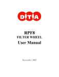
INTRODUCTION
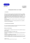
RPF Max is a motorized filter wheel running by means of the following two ports: 1) a standard
bidirectional port (parallel port); 2) a RS232 (serial port).
There are two versions of the wheel:
¾
¾
RPF Max-8: the 8-positions 2” filter wheel
RPF Max-16: the 16-positions 1” filter wheel
It stands out for its capability to place the 1” or 2” filters at high speed (50 ms between one filter
and the following one). In cascade connection mode, it can control up to 8 RPF Max units by
means of the same serial port.
It is possible to set the rotation speed and a different stop position for each filter.
The motor hold current is user adjustable.
This product can be customized, specifying different size, number of filters, input or output
adapters.
The typical applications are Photometry, Microscopy and color sequences.
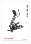
Fig. 1 RPF Max filter wheel: front and rear views, 8 and 16-positions inner disk
THE STANDARD SYSTEM INCLUDES:
•
•
•
•
•
•
assembled unit in light alloy with threaded 2” input;
RS232/Parallel interface;
2.5 m PC parallel link cable;
managing software for Windows ME/XP/2000;
115/230V power supply;
case, manual and 24 months of warranty.
PERSONAL COMPUTER MINIMUM REQUIREMENTS
•
•
•
•
CPU Celeron 1 Ghz
256 Mb of RAM
Microsoft Windows ME
RS232 port connecting the PC to the filter wheel
©2008 dta s.r.l. p. 3
RPF Max user manual
SOFTWARE INSTALLATION
Software installation of this instrument is particularly simple and intuitive. You must conform to the
following steps:
1.
Insert the CD ROM, provided with the filter wheel and the “Quick Install” will appear. Click on
RPF Max by the “Standalone programs for FW” menu:
p. 4 ©2008 dta s.r.l.
RPF Max user manual
2.
Now starts the installation of the program. Click on Next to continue the installation:
3. Select the folder where to install the RPF Max (we recommend you to choose the destination
directory suggested in the window below) and click on Next to continue the installation:
©2008 dta s.r.l. p. 5
RPF Max user manual
4. Now, the information are enough to start the installation of the RPF Max filter wheel. Click on
Next or Back to change any settings:
5. Wait while the Setup installs the software (just few seconds):
p. 6 ©2008 dta s.r.l.
RPF Max user manual
6. When the installation has been completed, a window like the one below will appear.
Click on Close to end the Setup
©2008 dta s.r.l. p. 7
RPF Max user manual
INSTALLATION OF THE RPF MAX TO YOUR PC BY MEANS OF THE SERIAL LINK
The following steps are fundamental to install the RPF Max filter wheel to your PC:
¾
It is suggested to make the connection operations with computer off.
¾
Install the software by the use of the CD-Rom provided with the filter wheel, following the
indications there reported.
¾
From the Programs/RPF_Max directory, edit the rpf.cfg file by text editor (as notepad or
similar), verifying the settings are coherent with the required ones. In particular, verify the
field relative to the used port.
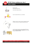
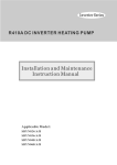
¾
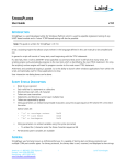
Put the provided serial 9-pin female connector of the link cable (see picture below – A) in
the selected serial port, then fix it by means of the two side screws placed on the
connector.
¾
Put the 25-pin female connector (see picture below – B) in the respective 25-pin male
connector of the RPF Max, then fix it by means of the screws placed on the female
connector.
¾
Put the male jack (out of the 12V power supply provided together with the filter wheel) in
the supply female jack (see picture below – C).
¾
Let run the handly program.
B
A
C
Fig. 2 Serial link cable
p. 8 ©2008 dta s.r.l.
RPF Max user manual
PARALLEL AND SERIAL INTERFACE
The parallel interface is made up of a link between the RPF Max and the PC on standard
bidirectional parallel port, while the serial interface is made up of a link by means of standard
RS232.
Hereafter you can see the 25-pin male connector of the RPF Max as well as the detailed
description of the included signals.
The following chart represents the signals on the pin of the connector
1
AD0
2
AD2
6
11
3
AD4
ERROR
7
GND
12
16
AD5
21
GND
4
AD6
GND
8
TX1
13
17
AD7
18
22
GND
23
5
/ACK
POW
9
ADDR
10
PRG
TX0
14
AD1
15
AD3
/BUSY
19
/STROBE
20
POW
+5V
24
RX1
25
RX0
AD0 – AD7 : COMMAND[0:7] parallel port (input)
/STROBE : /STROBE parallel port signal (input)
/ACK : /ACK parallel port signal (output)
/BUSY : /BUSY parallel port signal (output)
ERROR : notice of parallel port error (output)
GND : ground
POW : +12V RPF Max power supply (input)
+5V : +5V (output)
ADDR : pin of changing address
PRG : pin of firmware updating
TX1, RX1 : UART1
TX0, RX0 : UART0
- The communication speed on serial port can be 2400bps, 4800bps, 9600bps, 19200bps (see the
relevant paragraph).
- This specific kind of link can get up to a maximum distance of 50 m.
- With parallel port up to 20 m.
- All signals are standard CMOS 0-5V.
©2008 dta s.r.l. p. 9
RPF Max user manual
RPF Max SETTING
RPF Max ADDRESS SETTING
In serial mode RPF Max is identified by an address. Because of it, you can link up to 8 devices one
after the other. If the wheel doesn’t recognize its input address, it doesn’t answer and it stays
transparent.
The address recognized by the RPF Max can be found in location 3Fh of the inner eeprom : DTA
places it on address 0 (see the relevant section of the “ Programmer’s Manual”) : it usually is a
read-only .
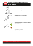
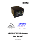
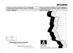
To modify the RPF Max address, it is necessary to short-circuit the pin 7 (ADDR) and 6 (+5V) of the 9pin female connector of the serial cable (see picture 3 – B).
Before performing this step, make sure your device is not powered !
Switch the wheel on and it’ll recognize the 0 address. Now the address can be changed by means
of a simple writing operation at the 3Fh location of the eeprom : only the lowest significant byte is
valid. Once this operation is over, switch the device off and eliminate the short-circuit. When
getting started, the filter wheel will recognize the new set address.
Otherwise, you can simply realize the identity address programming by means of the rpf.exe
handly program, just typing from the command console the following:
rpf /s n
where n is the address ranging from 0 to 7.
A
B
Fig. 3 A: Serial cable; B: detail
p. 10 ©2008 dta s.r.l.
RPF Max user manual
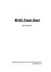
UPDATING OF THE FIRMWARE
RPF Max hosts a powerful microchip running every function with a re-plannable and updatable
firmware. To plan the firmware you need to build up a serial cable linking the wheel to the PC.
Hereafter you can find the chart.
RPF MAX PORT
CANNON 25 F
1
2
3
4
5
6
7
8
9
10
11
12
13
14
15
16
17
18
19
20
21
22
23
24
25
SIGNAL
-------POW
-TO BE SHORT-CIRCUITED
WITH PIN 23/
GND
TX1
--------GND
-TO BE SHORT-CIRCUITED
WITH PIN 10
RX1
--
UART 1
CANNON 9 F
-----------
POWER SUPPLY
JACK
NOTES
CENTRAL
+12V
5
2
------------
PRG
SERIAL GND
UART1 TX
EXTERNAL
3
--
POWER S. GND
VCC +5V
UART1 RX
CHART OF RPF MAX PLANNING CABLE
Please note: the power-supply jack has to be mounted as an output from the connector of UART1.
Fig. 4 RPF Max programming cable
©2008 dta s.r.l. p. 11
RPF Max user manual
In order to get to the programming stage, you also need to have the updated software as well as
the microcontroller programming software “M16C Flash Start (MSA0806)”
Here follow the steps to do in order to obtain the right updating of the software.
⇒
Switch the PC off, any device included.
⇒
Link the RPF Max to the PC by using the dedicated programming cable.
⇒
Feed the RPF Max and switch the PC on.
⇒
Start the software M16C Flash Start (MSA0806) and follow the instructions.
⇒ Once the programming has been carried out, switch both the PC and the wheel off. Then
change the programming cable with the communication one.
⇒ The wheel is ready to be used again.
RPF MAX CASCADE CONNECTION
You can get a cascade connection, up to 8 units, thanks to the serial link. The first cascade RPF
Max needs to be connected to the PC, the second by means of the 9 pin female connector(see
picture 5 – A) of its own cable to the 9 pin male connector (see picture 5 – B) of the previous wheel
and so on.
A
B
Fig. 5 Serial cable
p. 12 ©2008 dta s.r.l.
RPF Max user manual
SOFTWARE SETTING
RPF MAX HANDLER Rev. 1.2
Together with the RPF Max you are given a software controlling the wheel by means of serial port
“RPF Max HANDLER Rev. 1.2”.
It allows one to manage the wheel with Windows ME/2000/XP.
To install the managing program just start “setup” from the CD you can find in the wheel box.
This software looks for the wheel on the COM1.
Once the setting is finished, the program shows the presence of a single RPF Max as a default, with
suitable working parameters set by default.
To enable the control of more than one wheel and change the wheel parameters, it is necessary
to edit the file “rpf.cfg” (as shown in the following page of this manual) : it is in the same directory
as the software already installed.
Switch the RPF Max on, then start the software. The wheel is ready to be used.
©2008 dta s.r.l. p. 13
RPF Max user manual
RPF.CFG
**** Specify num of filter wheel in the same serial channel, range: 1..8
1
**** Specify num of filters on each fw, range: 8..16
8
**** Specify serial port, range: 0..15, 0 = COM1.. 15 = COM16
0
**** Specify baud rate, range: 3 = 2400, 4 = 4800, 5 = 9600, 6 = 19200
6
**** Enable holding torque: 0 = disable, 1 = enable
1
**** Set holding torque, range: 10..15984. 1 count = 62.5 ns of the ON period
15984
**** Filter offset, range: -127 to + 128. Applied after calibration
0
**** Calibration speed, Freq. (KHz) = 2/n. Range: 20000..10000
20000
**** Slope used in fast positioning, value are motor steps, range: 0..255
224
**** Start speed in fast positioning, Freq. (MHz) = 16/n. Range 32768..65535
65535
**** End speed in fast positioning, Freq. (MHz) = 16/n. Range 0..65535. 4096 for Sanyo-Denky, 16000 for MAE
4096
**** Enable (1) or disable (0) feedback positioning.
1
**** Delay after positioning (ms). Range: 0..65535. Suggested value: Sanyo-Denky 125, MAE 500
125
PLEASE DON'T CHANGE THE ORDER OF THESE PARAMETERS, AND DON'T ADD BLANK LINES BETWEEN
THESE.
MAX LENGTH OF A LINE IS 256 CHARS.
p. 14 ©2008 dta s.r.l.
RPF Max user manual
RPF Max (Rev 1.2) N POSITION FILTER WHEEL
PROGRAMMER’S MANUAL
RPF Max has two different connection systems : by means of parallel port or serial port.
On the contrary, the programming has been designed to be driven from the serial port only. The
filter wheel recognizes if the communication has been set by serial or parallel port automatically.
As soon as the device is on, it starts reading all the start-up settings from the inner EEPROM.
Immediately after, thanks to a calibration stage, it is located in filter number 0.
The device is identified by an 8-bit address serially, so you can connect up to 8 RPF Max in the
cascade mode.
Hereafter you can find the protocol transmission specifications.
RS232 SERIAL LINK AND TRANSMISSION PROTOCOL
The RS232 serial link is used with the following transmission parameters : either
2400, N, 8, 1 or 4800, N, 8, 1 or 9600, N, 8,1 or 19200, N, 8, 1 (see Appendix A : Setting of transmission
speed upon RS232).
The protocol uses printable ascii characters.
Every transmitted string consists of a head “$” character, an end-field “#” character and end-string
character represented by the CR (13) character.
Between the # character and the CR one, there are two hexadecimal figures showing the 8-bit
checksum of the string ( it is calculated from $ character to #, excluding these 2). Immediately
after the head “$” character you’ll find the RPF Max address (00-FF) one wishes to use. You will be
asked to provide 2 hexadecimal figures, up to a maximum range of 8 devices. For every string
transmitted to the wheel, it corresponds to another one standing for the answer : it is the command
processing confirmation. If the command has been carried out, the answer can be ACKXX, on the
contrary NAKXX. Instead of the ACKXX, a requested status can be sent.
Command string format
$ Addr Command # cksm CR
typical answer
$ Addr ACKXX#Cksm CR
If the address field does not include any valid value, no device will answer. Every RPF Max answers
after the carrying out of the command, the minimum response time being 20ms.
The checksum is calculated by summing up every character included between the $ character
and the # one (excluding these 2) on a 8-bit accumulator.
By means of the Command string, the instructions are given to the wheel. Command has a
dimension ranging from from 1 to 7 characters.
©2008 dta s.r.l. p. 15
RPF Max user manual
PARALLEL LINK AND TRANSMISSION PROTOCOL
The link is performed thanks to a 8-bit standard parallel port.
The protocol is as follows.
o
o
o
o
o
COMMAND [7:0] INPUT
/STROBE INPUT
/ACK OUTPUT
/BUSY OUTPUT
ERROR OUTPUT
The RPF Max waits for the input /STROBE signal to become low, then it reads COMMAND [7:0] and
lowers /ACK and /BUSY; it waits for /STROBE to come back to 1 in order to bring /ACK back to 1,
then it goes on with the interpretation and execution of the command which it has just received.
At the end of the execution, it carries /BUSY up to 1 and it sets or resets the ERROR flag according
to any error which might have occurred or not.
The word COMMAND [7:0] consists of : the 3 most significant bits (command [7:5]) identify the
command, the other 5 bits (command [4:0]) contains the data.
p. 16 ©2008 dta s.r.l.
RPF Max user manual
RPF MAX COMMANDS SERIAL MODE
In serial mode, RPF Max shows 24 instructions allowing the control of the wheel and the planning of
all parameters ( from the address to the number of filters and to the pilotage setting up of the
stepping motor). Ai and Di fields are expressed in hexadecimals.
What follows is the comprehensive list of the instructions.
CONTROL INSTRUCTONS
code 0
As an answer, RPF Max transmits a string concerning the revision of the firmware ( “RPF Max
Rev 1.2”).
o
VERSION
o
CALIBRATE
o
PLACEMENT code
o
TORQUE code
o
STATUS code
S
This instruction allows one to ask for the inner status of the RPF Max corresponding to the latest
placement instruction or calibration which has been performed. As an answer, the wheel can
either transmit the string STATUS00 showing that no error has occurred, or STATUS1 showing that
a calibration error has happened, or STATUS2 in case of a placement error.
o
POSITION
o
DIAGNOSTIC code
o
D_REPORT
code 1
RPF Max performs the adjusting by placing on filter number 0; if the adjustment has been
successful, it transmits the string ACK00, otherwise the string ACK01 (it means that the
adjustment can’t be carried out).
2D1D0
RPF Max goes onto the filter whose number is specified by the 2 figures D1D0 in hexadecimal.
Once the placement has been carried out, the wheel shows the string ACK00. If the number
specified in the instruction isn’t valid (as it exceeds the number of filters which the wheel can
host), the placement doesn’t come to an end and the wheel transmits the string NAK01
(unrecognized instruction). On the other hand, if the placement can’t be performed because
of a hardware failure, the wheel may transmit the string ACK02 (the placement has not taken
place) or the string ACK01 (the recalibration has not taken place).
9D0
This instruction allows one to apply (or not to do so) a holding torque to the motor of the RPF
Max (if it is still); D0 = 1 if you need to activate the torque, D0 = 0 if you need to deactivate it. The
RPF Max transmits the string ACK00.
code P
RPF Max gives back a string specifying the number of the filter currently in placement.
T
RPF Max carries out four series of automatic positioning, able to verify the correct working of
both the mechanics and the electronics (see Appendix D). For every performed positioning
the wheel transmits either the string ACK00 or ACK01 or ACK02, according to the positioning
outcome. At the end of the test, an hexadecimal number is given back showing how many
errors have taken place.
code RI0
This instruction allows one to enter four strings (I0 = 0-3) showing the latest diagnostic test (see
APPENDIX D).
©2008 dta s.r.l. p. 17
RPF Max user manual
PROGRAMMING AND SETUP INSTRUCTIONS
You are kindly recommended to use the wheel parameters as shown in Appendix B
o
TORQUE_VAL
code 3D3D2D1D0
The holding torque value depends on the length of the high level of a 1 Khz square frequency
wave applied to the motor. This value is set by means of the four hexadecimal figures D3 - D0
(16 bit). Every count is equivalent to an interval of 62,5ns. The minimum value to be set is 000Ah,
the maximum 3E70. The RPF Max transmits the string ACK00.
o
code 4D1D0
This instruction allows one to set a number of steps the wheel has to carry out at the end of the
calibration, by going on with the rotation trend or by inverting the rotation itself. The number of
steps ranges from –127 (D1D0 = 00) to + 128 (D1 D1 = FF) – the negative sign stands for the
inversion of the rotation -. The RPF Max transmits the string ACK00.
o
FILTERS
o
STEPS code
o
CIRCLE code
7D2D1D0
This instruction allows one to set the number of motor stepping to perform a full circle of the
wheel, the number being specified by means of the three hexadecimal figures D2D1D0. RPF
Max shows the string ACK00.
o
MOTOR_S
o
RAMP code
o
MSTEPI code
BD3D2D1D0
This instruction allows one to set the initial pilotage frequency of the stepping motor as far as
the placement stage is concerned. The frequency (MHz) is equivalent to 16/MSTEPI. RPF Max
transmits the string ACK00.
o
MSTEPF code
o
WRITE_EE code
OFFSET
code 5D1D0
This instruction allows one to set the number of filters you can mount on the wheel (it depends
on the internal disk), up to 16 (D1D0 = FF). RPF Max transmits the string ACK.
6D2D1D0
This instruction allows one to set the number of motor stepping between one filters and the
next one, the number being specified by means of the three hexadecimal figures D2D1D0. RPF
Max transmits the string ACK00.
code 8D3D2D1D0
This instruction allows one to set the pilotage frequency of the stepping motor during the
calibration stage. The frequency (KHz) is equivalent to 2/N (N stands for the number with 16 bit
set by D3D2D1D0). RPF Max transmits the string ACK00.
AD1D0
This instruction allows one to specify the length (by motor stepping) of the
acceleration/deceleration ramp of the motor during the placement stage. RPF Max transmits
the string ACK00.
CD3D2D1D0
This instruction allows one to set the maximum pilotage frequency of the stepping motor as far
as the placement stage is concerned. The frequency (MHz)is equivalent to 16/MSTEPF. RPF
Max transmits the string ACK00.
DA1A0D3D2D1D0
p. 18 ©2008 dta s.r.l.
RPF Max user manual
This instruction allows one to write in the inner eeprom : it’s the place where all pilotage
parameters of the device are memorized. By means of A1A0, one specifies the inner memory
address to be entered (ranging from 00h to 3Fh). The data to be written are given D3D2D1D0.
RPF Max transmits the string ACK00.
o
READ_EE code
EA1A0D3D2D1D0
This instruction allows one to read in the inner eeprom : it’s the place where all pilotage
parameters of the device are memorized. By means of A1A0, one specifies the inner memory
address to be entered (ranging from 00h to 3Fh). The RPF Max transmits the string including the
data of the memory location.
o
DIP_SW code
o
IR_CTRL codifica
o
IR_READ
M
This instruction allows one to get the status of the 8 inner dip switch (see APPENDIX A)
VD1D0
This instruction allows one to switch the positioning and calibration sensors on and off. If you
set D1 at 1, the sensor controlling the wheel position turns on; if you set it at 0, it turns off. If you
set D0 at 1, the sensor controlling the wheel calibration turns on; if you set it at 0, it turns off.
code I
This instruction allows one to read the information coming from by both positioning and
calibration sensors. Two figures are given back, C1 C0, showing (if at data 1) the performed
positioning or calibration respectively.
N.B.
C1 has to be at value 1 for every position of the wheel, while C0 has to value 1 in position ZERO only
(calibration positioning).
o
POS_FEEDBACK
code LD0
This instruction allows one to enable (or not to do so) the feedback control of the positioning. If
D0 is placed at value 1, the feedback has been activated; if it is placed at value 0, the
feedback is deactivated.
FEEDBACK NOTE
The feedback function allows the RPF Max micro to check the maintenance of the current
position before a new positioning might start. If the current position has gone lost (due to
special, external cause), the RPF Max carries out a calibration and then it shifts into the new
position.
o
DELAY code
KD3D2D1D0
This instruction allows one to trim the waiting delay at the end of every positioning of the RPF
Max. In this way the oscillations (due to the inertia of the system) are reduced. The delay time
corresponds to D3D2D1D0 ms.
©2008 dta s.r.l. p. 19
RPF Max user manual
RPF MAX COMMANDS PARALLEL MODE
In this mode, the RPF Max includes a reduced command set allowing one to drive the wheel and
enter a limited section of its parameters.
o
CALIBRATE
Command value
Parameter
000H
0none
The RPF Max performs the calibration by placing itself on filter number 0 again. If the
calibration can’t be carried out, it sets ERROR at value 1.
o
POSITION
Command value
Parameter
001H
00-n, where n=num of filters-1
The RPF Max goes to the filter whose number is specified by the five binary figures D4D3D2D1D0.
If the positioning can’t be carried out, the RPF Max sets ERROR at value 1.
o
TORQUE_VAL
Command value
Parameter
002H
00-1FH
The value of the holding torque depends on the length of the high level of a 1 kHz square
frequency wave applied to the motor. This value is set by means of the five binary figures D0 D4. Every count is equivalent to an interval of 625ns. The minimum value to be set is 00001 b,
the maximum 11111 b.
o
OFFSET
Command value
Parameter
003H
000H-0FH for positive offset
010H-1FH for negative offset
This instruction allows one to set a number of steps the wheel has to carry out at the end of the
calibration, by going on with the rotation trend or by inverting the rotation itself. The number of
steps ranges from –15 (D4D3D2D1D0 = 00000) to + 16 (D4D3D2D1D0 = 11111) – the negative sign
stands for the inversion of the rotation .
o
TORQUE
Command value
Parameter
004H
000H-0FH
This instruction allows one to activate or deactivate the holding torque of the stepping motor.
If D0 is placed at value 0, the holding torque is deactivated; if it is placed at value 1, the
holding torque is activated.
p. 20 ©2008 dta s.r.l.
RPF Max user manual
o
MOTOR_ S
Command value
Parameter
005H
000H-03H
This instruction allows one to set the pilotage frequency of the stepping motor during the
calibration stage. The frequency (KHz) is equivalent to 2/N (N stands for the number with 16 bit
set by D3D2D1D0). RPF Max transmits the string ACK00.
©2008 dta s.r.l. p. 21
RPF Max user manual
APPENDIX A
SETTING OF THE TRANSMISSION SPEED ON RS232
The two serial ports RS232 of the RPF Max (UART0 and UART1) can communicate at a speed of
2400 bps, 4800 bps, 9600 bps and 19200 bps. DTA has set it at 19200 bps; however, you can modify
it by using the dip switches 1 and 2 you can find inside the RPF Max. Hereafter you can look at the
settings of the two switches to select the four speed.
8
7 6
5 4
3
8
2
7 6
5 4
3
2
1
on
1
on
SETTINGS
8
7 6
19200 bps
5 4
3
SETTINGS
2
1
on
8
7 6
9600 bps
5 4
3
1
on
SETTINGS
4800 bps
PLEASE NOTE : THE DIP SWITCH POSITION 3 – 8 are not used!
p. 22 ©2008 dta s.r.l.
SETTINGS 2400 bps
2
RPF Max user manual
APPENDIX B
EEPROM MAP
The EEPROM includes every value relevant to any RPF Max parameter. Thanks to this every time
the wheel is on the internal microcontroller loads the functioning parameters automatically.
ADDRES
DATA
SANYO MOTOR
MAE MOTOR
Ind. 00h
CPVH
3E70h
3E70h
Ind. 01h
OFFSET_VAL
007Fh
007Fh
Ind. 02h
FILTERS
0008h
0008h
Ind. 03h
STEPS
0064h
0064h
Ind. 04h
CIRCLE
0320h
0320h
Ind. 05h
MOTOR_S
4E20h
4E20h
Ind. 06h
RAMP
00E0h
00E0h
Ind. 07h
MSTEPI
FFFFh
FFFFh
Ind. 08h
MSTEPF
1000h
3E80h
Ind. 09h
TORQUE
0001h
0001h
Ind. 0Ah
OFFSET_PS
0000h
0000h
Ind. 0Bh
POS_CTR L
0001h
0001h
Ind. 0Ch
DELAY
007Dh
01F4h
Ind. 3Fh
ADDRESS
0000h
0000h
CPVH : length of the high level of square wave running the holding torque (acceptable
range 000Ah – 3E70h).
OFFSET_VAL : offset value for calibration.
FILTERS : number of filters of the inner disk.
STEPS : number of motor stepping between one filter and the following one.
CIRCLE : number of motor stepping for the full rotation of the wheel.
MOTOR_S : it sets the pilotage frequency of the motor in calibration mode.
Freq.(kHz) = 2/MOTOR_S.
RAMP : number of motor stepping of the acceleration/deceleration ramp in the
positioning stage.
MSTEPI : it sets the initial pilotage frequency of the motor in the positioning stage. Freq.(
MHz) = 16/MSTEPI.
MSTEPF : it sets the final pilotage frequency of the motor in the positioning stage. Freq.(
MHz) = 16/MSTEPF.
TORQUE : if this parameter is set at value 0, the holding torque is deactivated; if it is, set at
value 1, it is activated.
OFFSET_PS : if this parameter is equivalent to 0, it means that the OFFSET_VAL value has
been set by serial port; otherwise, if this parameter is equivalent to 1, it means that the
OFFSET_VAL value has been set by parallel port..
POS_CTRL : if this parameter is set at value 1, the feedback positioning starts working; if it
set at value 0, the control is deactivated.
DELAY : it’s the gap in ms between a positioning and the other.
ADDRESS : this parameter sets the RPF Max serial address.
N.B.
The not bold value of the eeprom location is not significant.
©2008 dta s.r.l. p. 23
RPF Max user manual
APPENDIX C
ANSWERING MESSAGES OF THE RPF Max
ERROR MESSAGES
Hereafter you can find a list of error messages the RPF Max can give back as a result of the receipt
of an instruction by means of serial port.
NAK00 : receipt error; the input string can’t be decoded.
NAK01 : unrecognized or wrong instruction.
ACK01 : the calibration has not taken place; the reason is an hardware problem. Try to
clean the infrared positioning sensor with a jet of compressed air : it is placed
underneath, outward the filter disk.
ACK02 : the positioning has not taken place; the reason is an hardware problem. Try to
clean the infrared positioning sensor with a jet of compressed air : it is placed
underneath, inward the filter disk.
ACK03 : the operation is not allowed; this string is given back if you try to modify the
address of the filter wheel without having shot-circuited the ADDR pin (as specified in
the paragraph “Setting of the RPF Max address”).
AVVIA DIAGNOSTICA : you have carried out the D_REPORT command without carrying
out the diagnostic before.
DIAGNOSTIC MESSAGES OF THE INTERNAL STATUS
Hereafter you can find a list of internal status messages the RPF Max can give back as a result of
the receipt of the STATUS instruction (only from serial port).
STATUS00 : the last performed calibration or positioning instruction has been successful,
the wheel is working properly.
STATUS01 : the last performed calibration instruction has been unsuccessful. Try to clean
the infrared positioning sensor with a jet of compressed air : it is placed underneath,
outward the filter disk.
STATUS02 : the last performed positioning instruction has been unsuccessful. Try to clean
the infrared positioning sensor with a jet of compressed air : it is placed underneath,
inward the filter disk.
SUCCESSFUL EXECUTION MESSAGES
Hereafter you can find a list of messages showing a successful outcome as far as the execution of
the instructions given by serial port.
ACK00 : the instruction has been performed properly. This string is the answer to all the
given and carried out instructions but the VERSION instruction.
RPF MAX Rev. 1.2 : the VERSION instruction has been properly performed; the string
specifies the revision of the internal firmware.
p. 24 ©2008 dta s.r.l.
RPF Max user manual
APPENDIX D
DIAGNOSTICS OF RPF MAX
The RPF Max can carry out an auto diagnostic test allowing to check the right calibration of both
the mechanics and the electronics as well as the absence of any incorrect working stages. By
means of the DIAGNOSTIC (T) command, the wheel is asked to perform four positioning series : first
the wheel carries out a calibration, then it is placed on every filter included between 0 and N-1 (N
= number of positions of the wheel) like in a sequence. If the positioning fails, the wheel performs a
calibration before stepping into the following filter. In the second series, the wheel is placed on the
filters according to the following rule :
For X = 0; X<N/2; X++;
{POSITION =N/2+X;
POSITION =X;}
If a positioning fails, the wheel performs a calibration before stepping into the following filter. The
other two series are the same as the ones we have just mentioned.
At every series corresponds a string with N bit (binary figure) (the first being N + 1 as it also include
the outcome of the initial calibration) : here it is shown the outcome of every single positioning (0
means “performed”; 1 stands for “error”). The figure on the extreme left refers to position 0, the
other on the extreme right to the position N-1, except for the first string (in this case, on the extreme
left you can see the outcome of the calibration). You can get to the strings through the instruction
D_REPORT (RI0) – I0 ranges from 0 to 3.
APPENDIX E
C SOURCE EXAMPLES
Hereafter it is shown a C example RPF Max string encoding and transmission
void TxStr(char *tx, int len)
{
unsigned char cksm = 0, ch;
int
c;
TxByte('$');
// *tx is the string code for the RPF Max
// len is the lenght of the code
// standard function byte transmission
// on a serial port
// send $
// *** start of address sending
ch = ByteHex((Addr >> 4) & 0x0F);
// this function translate a bynary
// value to an hex character
TxByte(ch);
cksm += ch;
// checksum calculation
ch = ByteHex(Addr & 0x0F);
// this function translate a bynary
// value to an hex character
TxByte(ch);
// *** end of address sending
cksm += ch;
for(c = 0; c < len; c++)
{
TxByte(tx[c]);
cksm += tx[c];
}
// *** start of code sending
// *** end of code sending
©2008 dta s.r.l. p. 25
RPF Max user manual
TxByte('#');
// send #
ch = ByteHex((cksm >> 4) & 0x0F);
TxByte(ch);
ch = ByteHex(cksm & 0x0F);
TxByte(ch);
TxByte(13);
// *** start of checksum sending
// *** end of code sending
// send CR (13)
}
Hereafter it is shown a C example
of string decoding from RPF Max
int RxStr(char rx, int len, long tout)
//*rx is the decoded string
// from RPF Max
{
unsigned char cksm = 0, rcksm, add;
int
c;
char *bufrx = 0;
bufrx[0] = bufrx[1] = 0;
sread(bufrx, &c, tout); //this function receive a string from serial
//input the string ends with CR character
if(bufrx[0] != '$')
//controls that first character is $
return 1;
add = HexBin(&bufrx[1]); //decode address from hex char to bin value
if(add != Addr)
return 2;
cksm += bufrx[1];
//checksum calculation
cksm += bufrx[2];
for(c = 3; c < 80; c++)
// extract the code returned from RPF Max
{
// from serial string
if(bufrx[c] != '#')
{
cksm += bufrx[c];
rx[c - 3] = bufrx[c];
}
else
{
c++;
rcksm = HexBin(&bufrx[c]);
//controls the checksum
rx[c-4]=0;
break;
}
}
if(rcksm != cksm)
return 1;
*len = c - 3;
return 0;
}
p. 26 ©2008 dta s.r.l.
RPF Max user manual
SPECIFICATIONS
POSITIONING SPEED
0.05 s
NUMBER OF POSITIONS
8/16
STANDARD MOUNT
2’’
SPEED CONTROL
Yes
SERIAL INTERFACE
RS232 2400 9600 Baud
PARALLEL INTERFACE
8+4 bit input, 1 bit output
MAXIMUM FILTER THICKNESS
12 mm
BACKFOCUS
25 mm
POWER SUPPLY
12V 1A
DIMENSIONS
Φ 225 mm
WEIGHT
1,8 kg
OPTIONS
RGB-Max
50 mm RGB interference filter kit
NIK-Max
Adapter for Nikon lens
MIN-Max
Adapter for 42x1 mm lens
AR-Max
Adapter for HiRes
PAR-Max
Standard parallel port link cable
©2008 dta s.r.l. p. 27
RPF Max user manual
Link-2
Link cable for 2 RPF Max units with 2.5 m wheel base
Link-4
Link cable for 4 RPF Max units with 2.5 m wheel base
Link-8
Link cable for 8 RPF Max units with 2.5 m wheel base
p. 28 ©2008 dta s.r.l.
RPF Max user manual
INDEX
a
appendix a …… 22
appendix b …… 23
appendix c …… 24
appendix d …… 25
appendix e …… 25
answering messages of the rpf max …… 24
c
control instructions …… 17
c source examples …… 25
d
diagnostics of rpf max …… 25
e
eeprom map …… 23
i
introduction …… 3
installation of rpf max to your pc by means of the serial link cable …… 8
o
options …… 27
p
parallel and series interface …… 9
parallel link and transmission protocol …… 16
personal computer recommended requirements …… 3
programmer's manual …… 15
programming and setup instructions …… 18
r
rpf max address setting …… 10
rpf max cascade connection …… 12
rpf.cfg …… 14
rpf max commands parallel mode …… 20
rpf max commands serial mode …… 17
rpf max handler rev.1.2 …… 13
rpf max (rev. 1.2) n position filter wheel …… 15
rpf max setting …… 10
rs232 serial link and transmission protocol …… 15
©2008 dta s.r.l. p. 29
RPF8 user manual
s
setting of the transmission speed on rs232 …… 22
specifications …… 27
software setting …… 13
u
updating of the firmware …… 11
dta s.r.l. via giovanni cei 100, 56021cascina (pisa) - italy, web site: www.dta.it , e-mail: [email protected]
p. 30 ©2008