1
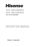
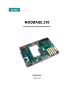
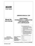
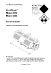
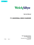
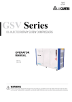
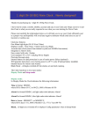
Inverter Series
R410A DC INVERTER HEATING PUMP
Installation and Maintenance
Instruction Manual
Applicable Model:
SBYN024/A/B
SBYN036/A/B
SBYN048/A/B
SBYN068/A/B
Dear Sir:
In order to use this machine safely, please read this user's manual carefully before using
and installation, also keep it for later use. DC inverter split heat pump units is a
professional machine, it may cause damage or hazard when wrong installed.
Please contact professional service company for installation and help.
CONTENTS
................................................................
1
2.SPECIFICATION ...........................................................
2
3.NAME OF EACH PART ...................................................
3
4.WIRE CONTROLLER SETTING INSTRUCTION..............
5
5.WIRING DIAGRAM ......................................................
14
1.FEATURES
6.INSTALLATION INSTRUCTIONS .................................. 16
7.MAINTENANCE ........................................................... 23
8.ATTACHED SHEET......................................................... 24
1. FEATURES
Our DC inverter type heat pump use environmentally friendly refrigerant
R410A, which also provides one of the highest energy efficiency ratings in
the industry. Compressor frequency changes according to outdoor environ
mental condition and the users' demands from the system.
LCD wire control panel for easy setting and control.
Special vibration absorbers on the compressor allow operation of the system
with ultra low noise from both the indoor and outdoor units, only for small unit
Operational indicators allow the users to monitor the system working status.
Microprocessor is programmed to allow operation under wide range of input
voltages from 165V~260V and soft starting with lower current draw at each
compressor start-up.
Auto-restart function keeps all settings in memory and automatically
resumes the operation after a power failure.
Compressor crank heating belts and outdoor heat exchanger heating belts are
available for extreme Nordic conditions, enabling the unit to work in very low
ambient temperatures with much lessened defrost frequencies. Both these
optional heaters are electronically controlled based on the outdoor ambient
temperatures and a sophisticated logic.
Self learning defrost logic constantly monitors the defrosting requirements and
automatically adjusts the intervals
Copper tube in shell heat exchanger is made with latest technology-- inner
grooved tubing, which extending the area of heat exchange in a more compact
coil , and therefore increased the operational efficiency
1
2.SPECIFICATION
Model
Function
Power supply
Heating capacity
Capacity
COP
Cooling capacity
EER
Operation current
Input power
Electric
data
Efficiency of power supply
Starting up current
Current of compressor motor
Input power of fan
KW/h
BTU/h
W/W
KW/h
BTU/h
W/W
A
W
%
A
A
W
Quantity of compressor
Compressor
Quantity of fan
Fan rotate speed
RPM
Water connection
inch
3
Water flow volume
m/h
kpa
Water pressure drop
Noise
Outdoor unit dB(A)
L
mm
Indoor unit
W
H
Net
L
dimension
W
mm
Outdoor unit
H
L
mm
Indoor unit
W
H
Package
L
dimension
W
mm
Outdoor unit
H
Net weight
Indoor unit
Outdoor unit
kg
kg
SBYN024/A/B SBYN036/A/B SBYN048/A/B SBYN068/A/B
Heating/Cooling
Heating/Cooling
220V-240V/1PH/50Hz
220V-240V/1PH/50Hz
7.35
11
14
20
24000
36000
48000
68000
2.9-4.5
2.9-4.5
2.9-4.5
2.9-4.5
5.15
7.7
9.8
14
17600
26500
33600
48000
2.0-3.5
2.0-3.5
2.0-3.5
2.0-3.5
7.5
11.4
14.4
20.6
2450
4450
1630
3100
98
98
98
98
8.1
13.6
7.9
13
6.6
9.1
6.4
9.5
90
90
90*2
90*2
1
1
2
2
Rotary
Rotary
Rotary
Rotary
1
1
2
2
850
850
850
850
1"
1"
1"
1"
2.28-4.8
2.28-4.8
3.0-6.9
3.0-6.9
12
12
15
15
48
49
50
52
580
580
690
690
430
430
510
510
220
220
300
300
880
880
1115
1115
420
420
470
470
800
800
1250
1250
650
510
280
980
460
965
45
51
2
650
510
280
980
460
965
45
55
770
580
390
1220
480
1360
58
107
770
580
390
1220
480
1360
58
111
3.NAME OF EACH PART
Indoor unit(SBYN024/A SBYN036/A)
Heat Exchanger
Elec.Box
Water flow
Water Pump
Water Inlet
Water Outlet
Power Cord
Refrigerant inlet/outlet
for low pressure
Refrigerant inlet/
outlet for high pressure
Outdoor unit(SBYN024/B SBYN036/B)
Piping
Air inlet
Air outlet
Drain outlet
3
3.NAME OF EACH PART
Indoor unit(SBYN048/A SBYN068/A)
Heat Exchanger
Water flow
Water Pump
Power Cord
Refrigerant inlet/outlet
for high pressure
Water Inlet
Water Outlet
Refrigerant inlet/outlet
for low pressure
Outdoor unit(SBYN048/B SBYN068/B)
Air outlet
Piping
Air inlet
Air outlet
Drain outlet
4
4.WIRE CONTROLLER SETTING INSTRUCTION
1.Wire controller
P1 P2
P3
P5
Initialization
Display screen
P10
P8
SEG1
SEG2
P21
SEG5
SEG6
P33
SEG7
SEG8
1
2
P12
P13
SEG3
P24
SEG4
P26
P36
P38
P39
P37
7
"Mode"button
"On/off" button
"Adjust/confirm" button
"Clear" button
"Up" button
"Down" button
1.1 LCD display instruction
Display position
Content
P2
Cooling mode
P24
Minute
P5
Heating mode
P26
Celsius Degree
/Fahrenheit degree
P10
Sequence
P36
"1"
P13
Data value
P37
"2"
SEG1,2
Temperature display
P21
Celsius Degree
/Fahrenheit degree
SEG3,4
Temperature display
P33
Clock display
SEG5,6
Hour
P38
Timing on
SEG7,8
Minute
P39
Timing off
Display position
Content
Remark: For the icons, that are not used for this heat pump will not display
in the setting.
1.2 "7"as indicating light, shows off when heat pump shut off, shows on and
green when heat pump turn on, flashing in red when heat pump is malfun
ctioning
5
3.WIRE
CONTROLLER
SETTING INSTRUCTION
7.PARTS
LIST
4.WIRE
CONTROLLER
SETTING INSTRUCTION
7.PARTS LIST
1.4 When heat pump is working under start-up state, SEG1、SEG2 display as
water in temperature , SEG3、SEG4 display as water out temperature; when
the heat pump is off under Stand by status, SEG1、SEG2 do not display and
SEG3、SEG4 display as ambient temperature.
Stand by status
Start-up state
1.5 When checking data , P10 & P13 shows on, SEG1 & SEG2 shows data number,
SEG3 & SEG 4 display data content; data for temperature value in Celsius
degree and P26 shows on ; data for time in minute and P24 shows on.
Malfunction
displays
Data Checking
1.6 When malfunction displays, SEG1 & SEG2 displays malfunction /defect code.
2.Button Operation
2.1 Change Mode
When the heat pump is working under start-up state, press "Mode"will change
the setting mode, P2 shows on in cooling mode, P5 shows on in heating mode.
Press"Clear"once may change between Celsius degree and Fahrenheit degree .
6
4.WIRE CONTROLLER SETTING INSTRUCTION
2.2 Temperature Setting
2.2.1 When heat pump is working under start-up state, press "up" or "down"
to enter temperature setting.
2.2.2 During your setting, P8 flash, SEG1& SEG2 display water in temperature,
P21 shows on all the time.
2.2.3 When stop pressing "up" or "down", setting finished, P8 shows off,
SEG1 & SEG2 return the displaying of water in temperature.
2.3 Clock Regulating
2.3.1 Press"Clear"for 3 seconds to enter clock
regulating mode, SEG5 to SEG8 & P33
start flashing, you may adjust the clock
by pressing "up" or "down";
press "clear", will finish the clock
regulating and exit this setting.
2.3.2 If not pressing any buttons, you will exit
the clock regulating and clock remain
no changed.
2.4 Timing Setting
2.4.1 Press " C onfirm "for 5 seconds to enter timing setting mode, hour area
is lightened and P38 flashes, enter timing on setting, you may adjust the
time for turning on the heat pump by pressing "up"& "down". After
setting finished ,press "confirm" ,P38 stop flashing,P39 flashes, enter
timing off setting, setting method is same as timing on.
2.4.2 Press " confirm " can enter to timing on setting or timing off setting.
2.4.3 In the setting of timing on and press "clear" may choose to set the
heat pump on timing "only for once with in 24 hours", display P38 , or
to set the heat pump timing on "once per day", display "P36,P38"; In
the setting of timing off, and press "clear" to choose to set the heat
pump on timing"only for once",display P39 , or to set the heat pump
timing off"once per day" "P37, P39";
2.4.4 After setting the timing on or timing off, press "confirm" button to
confirm the setting, and save the setting value.
2.4.5 Press “Confirm” button for 5 seconds to enter timing on setting,
re-press the “Confirm” button may cancel the timing off and exit.
2.4.6 If not pressing any buttons within 30 seconds, you will auto exit in
30 seconds.
7
4.WIRE CONTROLLER SETTING INSTRUCTION
Timing once with
in 24 hours on
Timing once with
in 24 hours off
Timing once
per day on
Timing once
per day off
1
2
2.5 Data Checking
2.5.1 Press " up " & " down " AT THE SAME
TIME for 5 seconds, enter " data checking "
mode; At this moment, the LCD panel will
display " NO. " on the left side , " 1 " means
number 1 data, " VALUE " on the right side
means the value of this data.
2.5.2 You may change the data number by pressing
either " up " or " down " button to check the
relevant data value.
2.5.3 Press "C lear " may exit data checking; if not
pressing any buttons within 30 seconds, you
will exit Data Checking in 30 seconds.
2.5.4 You may check the data whenever the heat pump is on or off.
8
4.WIRE CONTROLLER SETTING INSTRUCTION
2.6 Data Adjusting
2.6.1 Press "up" & "down" AT THE SAME TIME for 5 seconds constantly,
to enter "Data Adjusting".
2.6.2 If LCD panel flash on the left side, you may change the data number by
pressing "up" or "down".
2.6.3 Press "confirm"button , you may change the data value by pressing
"up" or "down", press "confirm" button again to save changed value,
and return to data number choosing.
2.6.4 When you are changing the data, you can exit Data Adjusting by pressing
"clear" button.
2.6.5 If not pressing any buttons within 30 seconds, you may auto exit Data
Adjusting and return normal display mode.
2.6.6 Data Adjusting can only be operated under "heat pump off " state.
2.6.7 Parameter table:
NO.
Content
0
Compressor continuously running
time for entering to defrost
1
Temperature for entering to defrost
2
3
Defrost time
Temperature to exit defrost
Range
30 ~ 90min
Duration Default
1min
45min
-17 ~ 0℃/1~32 oF
1℃/1 oF
1 ~ 12min
1min
8 ~ 30℃/46~86 oF
1℃/1 oF
3 ~ 10℃/33~50 oF
1℃/1 oF
5℃
1Hz
45Hz
-4℃/25 oF
8min
16℃/61 oF
4
Return difference value for starting
th e compressor
5
Energy saving frequency
40-55Hz
6
Hot water temp setting
26 ~ 45℃
1℃/1 oF
40℃
7
Cold water temp setting
12 ~ 25℃
1℃/1 oF
18℃
8
Temp.Differential protection range
9
Working mode of water pump
10
11
LO: When the unit is on,
when power suddenly
cut off, whether to restart
or not after power
resumption. 1 means yes
0 ~ 30℃/32~86 oF
0 :water pump keep working
1 :water pump ON/OFF
0~1
Reservation
Note: Among the temperature display , A~H means 10~17.
Fox example -A means -9 ℃, H9 means 179℃.
9
o
1℃/1 F
0
1
12℃/54 oF
0
1
4.WIRE CONTROLLER SETTING INSTRUCTION
2.7 Operational Status Checking
2.7.1 Press "M"for 5seconds, enter
"Operational Status checking"mode.
2.7.2 At the moment, screen alternately
display status“C0”and its relevant data.
2.7.3 Press "up"or"down" to adjust the status
and its relevant data change accordingly.
2.7.4 Press "Clear" once, to enter "Operational
Status Checking" mode.
2.7.5 Operational Status checking table.
Status
Content
Measure
C0
Water in temperature
℃
C1
Water out temperature
℃
C2
Ambient temperature
℃
C3
Outside Coil temperature
℃
C4
Air exhaust temperature
℃
C5
Compressor operational frequency
Hz
C6
Compressor current(Once for side)
A/D transform
value
C7
Radiator temperature
℃
Frost Protection Program:
When the heat pump is off, you may detect the water in temperature and
outdoor temperature.
First Frost-protection
Second
Frost-protection
Remark
When 2℃<water in temperature≤4℃, AND outdoor ambient
temperature ≤0℃, enter to First Frost-protection state , the system
will auto run the water pump mode.
When water in temperature ≤2℃ , AND outdoor ambient
temperature ≤0℃ , enter to Second-protection state, the system
will auto start to run in heating mode, until water in temperature
≥15℃ , OR outdoor ambient temperature >1℃, exit frost
protection.
If outdoor ambient temperature sensor failure, the water in
temperature will decide whether to start the frost protection or not.
If water in temperature sensor failure, outdoor ambient temperature
will decide whether to start the frost protection or not( and only have
First Frost- protection)
If both outdoor ambient temperature and water in temperature
failure, the system will not start frost protection.
If the compressor is not working because of system malfunction,
enter to First Frost-protection.
10
4.WIRE CONTROLLER SETTING INSTRUCTION
2.8 S1 Switch---Second set point
S2 Switch---Long distance demand for heating
S3 Switch---Long distance demand for cooling
Please refer to the wiring diagram for the location of above S1, S2 & S3 switch.
1) Heat pump turns on when S2 or S3 switch has well connected.
While S2 or S3 has connected, suddenly press the off button on the LCD controller. Heat pump will stop for 3
minutes. However, heat pump continues to trun on if S2 or S3 still has been connected after 3 minutes.
2) The Timer function is out of validity either S2 or S3 switch has connected.
3) Heat pump turns off when S2 or S3 switch is disconnected. Meanwhile, need to use LCD controller to turn on/off
the heat pump.
4) Second set point available when S1 switch has well connected.
At the same time, water temp set point setting decided by ambient temp, Parameter 6 and Parameter 7. (Both 6 & 7
parameter could be adjusted).
Parameter 6 (maximum setting range 50-60 °C )
Parameter 7 (minimum setting range 20-40°C)
A. When ambient temp < 5°C, set point temp refer to the data of Parameter 6.
B. When ambient temp >15°C, set point temp refer to the data of Parameter 7.
C. When < ambient temp < 15°C, set point temp = Data of Parameter 6-(Data of parameter6- data of parameter 7)/
(15-5)*(ambient temp -5).
For example, when ambient temp is 18 deg c, Parameter 6 is 60 deg c, Parameter 7 is 20 deg c.
Then set point temp=60-(60-20)/(15-5)*(18-5)
5)When S1 disconnected, set point temp control by LCD controller.
(Refer to the setting of Parameter 6 (default setting 55° C )
3. Malfunction table
[Note: sensor failure range(≤-50℃ or≥90℃)]
NO.
Subject
Indoor unit
LED Display
1
Wire controller
communication failure
E0
2
Outdoor power failure
E1
Wait for power
resumption
Outdoor power voltage failure
3
E2
Unit do not run
Water inlet temperature the
thermistor shorted or opened.
4
Water inlet
temperature sensor
Water outlet
temperature sensor
E3
Unit still runs
Water outlet temperature
thermistor shorted or opened
5
Outdoor coil
temperature sensor
E4
Unit do not run
6
Outdoor high/low pressure
protection
E5
Unit do not run
7
Outdoor mould sensor failure/
high temp protection
E6
Unit do not run
Outdoor radiator temperature
sensor shorted or opened
Water flow failure
E7
Unit do not run
When the water pump is running,
flow switch continuously
off for 10 seconds
Communication failure
E8
Outdoor unit do
not run
Connect to power supply,
communication signal
will stop for 30 seconds.
E9
Outdoor unit do
not run
EA
Outdoor unit do
not run
Outdoor unit frequently
current protection
12
Compressor start or
operation failure
Outdoor
unit over-current
Compressor air exhaust
temperature sensor
EB
Unit do not run
Compressor air exhaust
thermistor shorted or opened
13
Ambient
temperature sensor
EC
Unit do not run
Ambient temperature
thermistor shorted or opened
14
Outdoor module over
-heating, over-current
ED
Outdoor unit do
not run
15
Outdoor air exhaust
over-heating protection
or compressor over
heating protection
16
Outdoor coil over
heating
8
9
10
11
Malfunction
Explanation
Problem with the
communication between wire
controller and indoor unit
EE
EF
11
Outdoor coil thermistor
shorted or opened
4.WIRE CONTROLLER SETTING INSTRUCTION
4. Malfunction & Solutions
4.1 Temperature Sensor failure
4.1.1 Once any of the temperature sensor failure happened
( excluded the water outlet sensor), please stop the unit.
4.1.2 After temperature sensor working normal, unit resume
for operation.
4.2 Water flow failure
4.2.1 When water pump works and the flow switch continuously
off for 10 seconds, it shall be water flow failure.
4.2.2 Once water flow failure happened, compressor and water
pump stopped at once and malfunction code appears,
malfunction code will be cleared after power resumption.
5.Indicating lights on electric control board.
5.1 For convenient maintenance, there are 2 LED lights on
outdoor board.
5.2 LED1 is communication and defrost indicating light.
Normally, when outdoor unit receive signal from indoor unit,
LED1 will flash regularly, when the system is performing
defrost function, LED1 will be on for long time.
5.3 LED2 is malfunction indicating light . For normal operation,
LED2 is off. If there is any malfunction, different malfunction
will make LED2 flash differently.
5.4 LED3 is power indicating light. When it is on, then storage
capacitor is electrified. When the unit cut off power, the
electric charge from storage capacitor will take some time for
discharge, maintenance shall not begin until the LED3 is off !
12
4.WIRE CONTROLLER SETTING INSTRUCTION
LED2
NO. Malfunction reason display
1
2
Voltage protection
1 flash
Malfunction
symptom
Compressor stop
Detecting Method
When DC voltage is lower than
226/175V(compressor: stop/run) ,
stop the compressor; after voltage
return to normal , restart the unit.
Compressor stopped for
High voltage protection 2 flash(es) 3 minutes and then restart
Ambient thermistor is
shorted or opened.
3
Ambient
temperature sensor
3 flash(es)
4
Reservation
4 flash(es)
5
Reservation
5 flash(es)
6
System coil A or air exhaust
temperature sensor failure
6 flash(es)
Unit stop
System coil A or air exhaust
thermistor is shorted or opened.
7
System coil B or air exhaust
temperature sensor failure 7 flash(es)
Unit stop
System coil B or air exhaust
thermistor is shorted or opened.
8
Electricity sensor failure 8 flash(es)
Unit stop
9
Low voltage protection 9 flash(es)
Unit stop
Compressor stopped
for 3 minutes and then
restart
Electricity sensor damaged
or not inserted to detecting
wire
Cut off power to protect the
switch ; after voltage return
to normal, resume operation.
10
Air exhausting temperature
over heating protection
When air exhaust temperature
is over 109℃ and last for 10
Compressor stopped for seconds, compressor stop running ;
10 flash(es)
3 minutes and then restart
after 3 minutes(temperature
is lower than 90℃) restart.
11
Unit electricity protection
11 flash(es)
Compressor stopped for If this happened 4 times within 30
3 minutes and then restart minutes, the unit will stop running.
12
System driver module
over-current ,over-heating 12 flash(es)
or undervoltage protection
Compressor stopped for
If this happened 4 times within 30
3 minutes and then restart minutes, the unit will stop running.
13
System B drive module
over-current ,over-heating 13 flash(es)
or undervoltage protection
Compressor stopped for If this happened 4 times within 30
3 minutes and then restart minutes, the unit will stop running.
14
System drive
module A failure
14 flash(es)
Unit stop
System drive module A or
PCB damaged.
15
System drive
module B failure
15 flash(es)
Unit stop
System drive module B or
PCB damaged.
13
5.WIRING DIAGRAM
Indoor unit
Model:SBYN024/A/B SBYN036/A/B
RED
P5
P6
P4
N
P3
P11
COMM1
P13
P12
Water flow
DIN1
P7
BLU
ASL-MGH077
CN6
CN9 CN8 CN7
YLW/GRN
VH2
CN5
CN4
T1
T2
Transformer
VH1
OUT1
1 L N
TO OUTDOOR UNIT
WATER PUMP
L
P1 P2
DIN2
CN3
WIRING DIAGRAM
BRN
COMM2
S1 Second set point switch
S2 Long distance demand for heating switch
1 2 3 4 5 6
S3 Long distance demand for cooling switch
S2
TR Return water temperature sensor
S3
TW
Wire controller
TR
S1
TW Water outlet temperature sensor
Model:SBYN048/A/B SBYN068/A/B
P6
P5
P4
P3
N
P13
P11
COMM1
DIN1
BLU
ASL-MGH077
CN9 CN8 CN7
T2
VH2
CN6 CN5 CN4
T1
Transformer
VH1
BLU
YLW/GRN
Water flow
CN3
P12
OUT1
P7
1 2 L N
TO OUTDOOR UNIT
WATER PUMP
L
P1 P2
DIN2
WIRING DIAGRAM
RED
BRN
COMM2
S1 Second set point switch
S2 Long distance demand for heating switch
S3 Long distance demand for cooling switch
TR Return water temperature sensor
1 2 3 4 5 6
S2
S3
S1
TW Water outlet temperature sensor
14
TW
TR
Wire controller
5.WIRING DIAGRAM
Outdoor unit
Model:SBYN024/A/B
CAPACITOR
REACTOR
COMPRESSOR
U CM
V
W
RECTIFIER BRIDGE
ORG
YLW
BLK
YLW
BRN
GRN
CRANKSHAFT HEATER
FM
Do
Y/G
CONDENSER HEATER
YLW
D
CDH
RV
IPM
FML
IPM02B
BLK
N
BLU
RED
WHT
P
DCOUT-
W
V
U
CH ACOUT1
RV FMC
DCIN- CH
RV
CDH
CAPACTIOR
FMH
DCIN+
MWH065
DCOUT+
YLW
CN1
FILTER
CN101
5
ACOUT2
BLU
ACIN2
CN6
N'
PE
COMM ACIN1
CN201 CN202 CN203
L'
N
L
C L H
WHT
YLW
BLU
BLK
RED
Low pressure
YLW/GRN
protective
TA TO TE
switch
1 L N
High pressure
protective switch
TE
Environment temperature sensor
TO
Outdoor coil temperature sensor
TA
Air exhaust temperature sensor
C N
TO INDOOR UNIT Power supply
220-240V/AC/50HZ
Model:SBYN036/A/B
WIRING DIAGRAM
RED
BLU
RED
CRANKSHAFT HEATER
REACTOR
Do
4-WAY VALVE 1
CONDENSER HEATER
YLW
YLW
FAN MOTOR
D
CHASSIS HEATER
LB DC+
D1
AC2
LA
AC1
DC-
N
DCOUT-
FM
DCIN-
ACOUT1
NOUT
DCOUT+
DCIN+
CAPACTIOR
W
V
IPM070-V3
OUT5 OUT4 OUT3 OUT2 OUT1
U
ACOUT2
P
5
COMPRESSOR
U
YLW/GRN
V
W
CM
CN8 CN3 CN2
ACIN1 RED
CN6
T101
FILTER
N'
ACIN2
CS
CN101
TR
BLU
MWH089-V2
L'
PE
N
L
COMM
CL H
BLK
TA TO TE
BLU
YLW
RED
CN2 CN1
RED
BLU
YLW/GRN
Low pressure
protective
switch
TR Radiator temperature sensor
TE
Environment temperature sensor
TO
Outdoor coil temperature sensor
TA
Air exhaust temperature sensor
High pressure
protective switch
1 L N
TO INDOOR UNIT
15
C N
Power supply
220~240VAC/50HZ
5.WIRING DIAGRAM
Outdoor unit
CP Compressor overheat protection
TA A TO A TA B TO B
HI High pressure protective switch
D1 Chassis heater
TE Environment temperature sensor
D
TO A Outdoor coil temperature sensor A
TA A Air exhaust temperature sensor A
S604
REACTOR
L
L-OUT
PE
N
CONTACTOR
~
~
AC DC
HI
S603
MDQ-60
BRIDGE RECTIFIER
Cc
CB
CA
LO
ASL-XL044-V2
2 1
C N
2
CN301
COMM
L N
2 1
L'
TO INDOOR UNIT
TE
LO Low pressure protective switch
Do Crankshaft heater
POWER
CAPACITOR
ELECTROLYTIC
CAPACITOR*2
2200MFD/400VDC
COMPRESSOR
W
1
CN103
DCIN
1
CP
CURRENT LIMITING BOARD
CS
CN204 ASL-MWH038A
AMB
CM2 Y/H
N
U V
CN1
MODULE B
5
2
2
S615
CN209
P
IPM02B-30A
U
V
W
IPM02B-30A N
CN1
MODULE A
5
CN101
S601
CN102
P
W
U V
L
N
S602
CDH
S614
RVB
S613
2
S611
2
S610
S612
4 WAY B
4 WAY A
Do
CN200
ETA
Cn201
CTA
CN202
ETB
CN203
CTB
S608
S609
RVA CH
S607
FML FMH
S606
FMN
D/D1
S604
S605
U
V
W
COMPRESSOR
YLW/GRN
CM1
S603
OR
CAPACTIOR
FM2
FM1
WIRING DIAGRAM
CAPACTIOR
FAN MOTOR 2
FAN MOTOR 1
Model:SBYN048/A/B SBYN068/A/B
FILTER
PE
L
Condenser heater
TO B Outdoor coil temperature sensor B
TA B Air exhaust temperature sensor B
N'
N
Power supply
220~240VAC/50Hz
6.INSTALLATION INSTRUCTIONS
Installation instructions
1. Unit installation
1).Installation location
Outdoor unit
² The outdoor unit installation shall be conform
to the same requirement as air conditioner
outdoor unit .
²Should be installed in a larger & wellventilated place.
Outdoor unit
²Installation location should ensure unhindered
and no access to air outlet (Installation
dimension refer to the right pic).
²The installation base or bracket should
be solid, to ensure the stable operation.
²Make sure the unit is vertical after installation, and no incline.
²Make sure not to install the outdoor unit in any condition of pollution, corrosive gases,
dust and sand , and fallen leaves, etc.
²Installation location shall not next to place where is flammable or explosive or have fire.
1000mm above the top
Air inlet
Air inlet
Air inlet
Above 1000mm
Air outlet
Above 2000mm
16
Above 1000mm
Air inlet
Above 200mm
6.INSTALLATION INSTRUCTIONS
I ndoor unit
² The installation site shall be connected to the water gutter or waterspout so the unit can
drain water easily.
² Indoor unit can be installed in the indoor and outdoor walls (based on the size of the indoor
unit and the load-bearing capacity of the building, etc.).
²Installing base shall be solid to ensure a stable running for the unit.
² Do not install the water tank next to pollution or corrosive gas.
Pressure tank(Note: only an option for customer to buy if necessary. )
²Water tank shall be installed in outdoor such as balcony, roof and floor, also can be
installed indoor .
²Water tank shall be installed vertically, installation site shall be solid and able to bear
500KG weight. Can NOT be hung on the wall.
²Valves shall be added around water tank and the connections on return water and hot
water supply .
²Do not have water tanks installed in the pollution, corrosive gases place.
2).Unit installation
²Units base can be installed as cement concrete structures, steel brackets can also be used,
add the shockproof rubber pads , make the base surface flat.
²Units can be designed based on the working performance.(See Table of technical
performance parameters)
²Fix the unit by bolts at the bottom of unit.
²There shall have Draining gutter or waterspout on the floor .
²Normally required to install in the place where setted cement concrete base.
★ I ndoor unit installation
Bracket
2. Drill the holes on the wall.
1. Use the bracket to mark the position
of the indoor unit on the wall.
Small bolt
expansion bolt
4. Hang the indoor unit on the
bracket.
3. Insert the expansion bolts (3pcs,
M8) into the holes. Then fix 2
small bolts on the above small
holes.
17
6.INSTALLATION INSTRUCTIONS
★ Outdoor unit installation
1. Mark the location of brackets as per model size. (Reference to size B ).
2. Make sure the 2 stainless steel brackets are well fixed.(Fix 8 screws on the floor.)
3. Let the rubber cover the HP installation stand.(4 pcs rubber for each unit)
4. Carry the hp outdoor unit on the brackets,and insert the bolt. (4 pcs bolts for
each unit)
5. Fasten the nut. (4 pcs nuts for each unit)
Dimension of outdoor bracket
Model
Size
SBYN024/B
SBYN036/B
Measure: mm
SBYN048/B
SBYN068/B
L
400
460
L1
430
490
H
300
300
W
85
85
W1
110
110
N
380
440
B
541
760
①
②
① Bolt(M8×40mm)
③
② Bolt cover (φ8×25mm)
③ HP installation stand
④
④ Rubber
⑤ Outdoor bracket
N
B
⑤
⑥ Nut(M8)
H
W1
W
L
⑥
SBYN024/B SBYN036/B
L1
H0
expansion bolt
B
C D
A
SBYN048/B SBYN068/B
E
Dimension of outdoor unit
Model
H0
Size
18
SBYN024/B
SBYN036/B
Measure: mm
SBYN048/B
SBYN068/B
A
380
440
B
541
760
C
366
427
D
410
470
E
897
1117
H0
800
1250
3.WIRE CONTROLLER SETTING INSTRUCTION
6.INSTALLATION INSTRUCTIONS
2.System Copper tubing connections.
Note: NOT to twist the copper tubing, MUST NOT have fractures.
1).Drill aφ70 hole through the wall between indoor unit and outdoor unit .
2).Take off the indoor connecting pipe caps and connect them to the indoor pipes.
3).Take off the outdoor unit high and low pressure pausing valve caps( picture 3) and
connect the relevant pipes .
3.System pipeline evacuation.
Note: after the connections for indoor and outdoor units, indoor units and connecting
pipes SHALL be emptied by a air vacuum pump. Otherwise the air that contains
water will enter into system and cause abnormal for the compressor.
When using the vacuum pump( each low pressure pausing valve shall perform below actions )
1)Inject the manifold valve with soft tubing and connect to low pressure pausing valve
injection hole.
2)Connect the injection soft tubing and the vacuum pump .
3)Completely open the manifold valve lo(low pressure) handler.
4)Start the vacuum pump for air vacuuming. At the beginning, slightly loose the low
pressure pausing valve screw , check if any air go inside( the vacuum pump noise will
change , millimeter indicator change from minus to 0. and then tightly screw the nut.
5)After the air vacuuming finished, completely close the manifold valve lo low
pressure)handler, stop the air vacuuming pump .
( Air vacuuming shall last ast least 15 minutes, and make sure that the millimeter
Air side
indicates -1.0X10 5 Pa(-76cmHg).
6)Thightly close the pressure gauge valve,
Manifold valve
and completely open the high pressure
Multimeter
Pressure gauge
and low pressure pausing valve.
7)Remove the injection soft tubing from
-76cmHg
the low pressure pausing
8)Tightly screw the low pressure pausing
Hi handle
Lo handle
valve cap.
Injection
9)Leakage check: Use the soapy water to Injection soft tubing
soft tubing
check each tubbing connections and
Air vacuum pump
screws, if there is any leakage, use a
spanner to tight it closed utill no
leakage. NO LEAKAGE is allowed.
High pressure pausing valve
19
Liquid side
Low pressure pausing valve
Picture 3
6.INSTALLATION INSTRUCTIONS
4.Water pipe connections
Installation note.
⊙ All water connections shall be conveniently for water draining . Drainage valve shall
be installed on indoor unit water outlet
⊙User's water pressure shall lower than 0.6Mpa.
⊙All pipelines should choose metal pipe (such as stainless steel, with Lining Plastic and
lining stainless steel and thin-walled copper pipe or, etc.). The use of plastic pipe
(such as the PP-R, ABS, etc.) should consider the pipeline expansion between the host
unit and water tanks .
⊙All system pipelines need to keep warm in the winter (according to the local winter
temperature) to avoid the broken of water supply and pause valve.
Water system installation
⊙All the pipeline tubing should be matched as shown on the manual, and in accordance
with national corresponding construction standards.
⊙Installation of water pipes should be straight and flat, pipeline collocation should
be rational, ensure to minimize bending; reduce the resistance loss of the water system.
⊙Pipeline and connecting parts are not allowed a leakage phenomenon.
⊙After the installation of circulating pipe between tap water pipes, host unit and water
tanks ,should carry out water leakage testing, and eject the sewage to ensure the sy
stem's cleanness.
⊙If no water leakage, keep the hot water pipe warm.
5.Project example:
Application of heat pump water heater engineering systems have different forms. Here
are two kinds of stand-alone group water heating system, only for your reference.
Building electric box
TA
Indoor unit
Wire controller
Outdoor unit
Power connection
Refrigerant pipe
water pipe
PC
2
PC
2
F1 V V
20
F1
6.INSTALLATION INSTRUCTIONS
Label
Element
Supplied
CD
Remote control
Y
F1
800υm fillter with 2 isolation valves
N
PC
Heating floor pipe
N
R
filling
N
TA
Building electric box
N
V
Water draining
N
Observations
User (Daily Hot Water,Radiator......)
PU
Building electric box
TA
Indoor unit
Wire controller
Refrigerant pipe
water pipe
2
2
F1 V V
F1
Pressure tank
Outdoor unit
Power connection
PU
Water supply
Running Test and operation
1. Preparatory work before the running test.
a) Inspection of heat pump water heater units:
⊙ Check if the unit appearance and the pipeline system were damaged during transport.
⊙ Check if there is air exist in the water pipes, if yes, should empty all the air inside by the
manual exhaust valve and the exhaust valve on the water pumps.
⊙ Check if the fan motor interference the fan fixing board and fan protection net.
b) Check the electricity distribution System
⊙ Check if the power supply same as shown on manual and rating label.
⊙ Check if all the power supply and control wiring are all well connected, check if the
wiring is connected as wiring diagram and reliability of earth wiring.
c) Check Pipeline system
⊙ Check the pipeline system, make sure the water supply pipes, water return pipes, pressure
gauges, valves are installed correctly.
⊙ Check if having opened all the valves that should be opened, and having closed all valves
that should be closed.
⊙ Check if all necessary warm preservation are good.
21
6.INSTALLATION INSTRUCTIONS
2. Running test
The running test must be performed by professional technicans !
Overall test can be run if the entire system inspection is conformed to regulations.
Connected to power, start the heat pump, host unit delays three minutes then auto-start.
For three-phase power supply unit, first check whether the fans and pumps' rotary
direction correct or not, if not, immediately shut down the power and adjust phase
sequence. Measure the compressor operation current, and if any abnormal noise.
Check whether the unit conform to the requirements, run for a period of time
(general 3 days),after that, the unit can be used normally.
3.Normal operation
⊙ Heating process: start up - water pumps runs --fan motor runs-compressor runs
⊙ Operation Control:
1)Compressor running control
a. Unit will adjust the target frequency according to the ambient temperature, setting
temperature and protection function , and to determine to compressor running frequency.
b. Once compressor starts, it is necessary to run at least 1 minutes before you shut it off.
(except power cut off)
2)Fan motor control
a. The operation of the fan motor have a connection with the compressor on/off.( time
sequence see below )
b. Fan motor starts by 5 seconds earlier than the compressor and turn off by 5 seconds later
than compressor.
5 seconds
5 seconds
Compressor
Fan motor
3) Water pump control
a. The water pump runs as soon as the unit is on; when the unit is off, water pump will not
stop running after 10 seconds .
b. Water pump runs when defrosting .
4) 4-way-valve control
a. 4-way-valve is not electrified when performing heating mode.
b. 4-way-valve change direction for
4 seconds before compressor starts.
Compressor
c. 4-way-valve is electrified when
defrosting.
d. When the unit off, if 4-way-valve is still 4-way-valve
electrified, then it will delay for
Heating
3 minutes before shutting off.
22
7.MAINTENANCE
Maintenance
DC inverter split heat pump units are hi-automatic equipments, please perform regular in
spection termly . If the unit can be maintained efficiently in a long-term , the operating
reliability and service life will have an unexpected increase.
1.The extra water filters should be cleaned regularly to ensure clean water quality of the
system, and to avoid damage caused by dirty water filter blocking.
2.Users should pay attention for usage and maintenance to below : all units' protection
devices are set up before leaving factory, do not make any adjustment by yourself.
3.Frequently check the power supply and electrical wiring system is solid or not, whether
electrical components are abnormally working, if yes, should timely maintained and
change for a new one.
4.Perform regular checks of the water supply system, check whether the tank safety valve,
liquid level controller and exhaust devices work properly, so as to avoid air into the system,
and reduce the water cycle volume, thus affect the heating function and operation reliability.
5.Check whether pumps and water valves are normally working or not, whether water tubing
and water pipes connector are leakage or not.
6.The unit and around should remain clean, well-ventilated. Regularly clean (1-2 month)the
side air heat exchanger to maintain a good effect of heat exchange.
7.Frequently check whether each part of the unit work normal or not, check whether there is
oil on the pipeline joints and charging valve to ensure that no refrigerant leakage.
8.Do not piling up debris around the unit, so as not to block from air inlet and outlet, the unit
around should be kept clean the dry, well-ventilated.
9.If the unit stops for a longer time, should drain all the water in the pipeline, cut off power
supply, and put on the protective cover. When re-run the unit, complete inspection is a
must before reboot.
10.When unit failure, and the user can not resolve the problem, please call our Company in
local maintenance department, in order to promptly send people for maintenance.
11.Host condenser cleaning. We propose to use 50℃-60℃, and 15% hot phosphoric acid for
condenser cleaning, launch the circulating pump of the host unit for three hours' cleaning,
finally rinse with water three times. (Propose to back up a 3-way connector when installing
the pipeline, block one joint),in order to clear the connection pipe. Do not use corrosive
cleaning fluid for condenser cleaning.
12.Water tanks need to remove the Water scale after some time (normally two months,
according to the water quality of local place).
23
8.ATTACHED SHEET
1. Indoor water pump performance curve
● SBYN024/A /B, SBYN03 6/A/B
H
(m)
7
RS
6
-2
5/8
5
)
S
Total
Delivery 3
lift
2
(m)
-2
-2
8
S
5/
R
5/
8(
m
in
1
)
0
ax
R
4
(m
0
1
2
3
4
5
6
Water Flow Volume Q(m3/h)
●
SBYN048/A /B, SBYN068/A/B
H
(m)
7
RL-25/7.5
6
5
4
Total
Delivery 3
lift
2
(m)
1
0
0
2
4
6
8
Water Flow Volume Q(m3/h)
2. Water pump and piping installation notice
Horizontal
piping length
Suction Height
6m
26m
5m
37.5m
4m
49m
3m
50.5m
24
※ All the product information has been carefully checked, our company will
be free from printing error.
※ The actual products may be slightly different from those images shown in
this manual.
※ Specifications are subject to change without notice for further improvement.
Please refer to the name plate on the unit for the updated specifications.