1
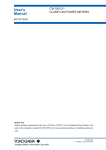
MITSUBISHI ELECTRONIC MULTI-MEASURING INSTRUMENT
MODEL
ME96NSR
MITSUBISHI Electronic Multi-Measuring Instrument NS Series features high performance
and crystal clear display.
With simple operating functions, NS Series is the best support your measuring and monitoring systems.
Upper/lower limit monitoring up to 4 items
Harmonics monitoring
Measures import/export active energy
4 items displayable
Backlight automatic off function
Output functions for 7 items
Pulse width settable
Pulse output at 2 points
Analog output range settable
DIN Size 96×96mm
3P4W/3P3W Common Use
Add-on Type Output Options
CE Marking
Conforms to EU RoHS Directive
(2002/95/EC)
ModBus communication
CC-Link communication
Simple settings
Simple operations
Features
Functions
Dimensions / Mounting / Wiring
Specifications
Related Products
Safety Precaution
1
6
23
26
28
29
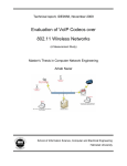
Features
ModBus Transmission System (ME96NSR-MB, Optional Plug-in Module ME-0052-NS96)
● ModBus communication system to monitor computers.
● By adding the optional plug-in module ME-0052-NS96, monitoring of contact input
signal and ON/OFF of contact output signal can be controlled remotely.
● Digital input signal can be latched for over 30ms, and there is no need for external latch
circuits.
Central Monitor
RS485/RS232
Converter
Optional Plug-in Module
ME-0052-NS96
RS232
<ModBus Interface Specifications>
• Max. Baud Rate 38.4kbp
• Max. Connection Distance 1000m
• Max. Connection Units 31
RS485 (ModBus)
SHT (OFF)
CC (ON)
AL
PAL
TAL
ACB Status
<Optional Plug-in Module ME-0052-NS96>
• Digital Input 5 points (24VDC)
• Digital Output 2 points (35VDC)
CC-Link Transmission System (ME96NSR, Optional Plug-in Module ME-0040C-NS96)
● Optimum transmission system for remote monitoring using MITSUBISHI PLC.
● Remote monitoring of contact signal leading to less wiring, less spacing.
● Digital input signal can be latched for over 30ms, and there is no need for external latch
circuits.
NETWORK
MELSEC Series
CC-Link
Abnormal Signal (Facility)
Abnormal Signal (Earth Leakage)
Abnormal Signal (Temperature)
Circuit Breaker Status Signal etc
<CC-Link Interface>
• Max. Baud Rate 10Mbps
• Max. Connection Distance 100m (10Mbps)
to 1000m (156kbps)
• Max. Connection Units 42
• Digital Input 4 points (24VDC)
Analog Pulse Transimission System (ME96NSR, Optional Plug-in Module ME-4201-NS96)
● Can remotely monitor A, DA, V, W, var, VA, PF, Hz, Harmonics Current RMS Value,
and Harmonics Voltage RMS Value at 4 to 20mA output. (Max. of 4 outputs)
● Active energy and reactive energy can be remotely monitored by pulse output.
(Max. of 2 pulses)
● Can remotely monitor upper/lower limit alarm by contact output. (Max. 1 point)
NETWORK
Analog Output
Pulse Output
Alarm Output
<Alanog Output Specification>
• 4 to 20mA
• 4 outputs
• Maximum 600Ω
<Pulse Output Specification>
• No-voltage a contact
• 35VDC 0.1A
• Pulse width 0.125, 0.5, 1s is selectable
<Contact Output Specification>
• No-voltage a contact
• 35VDC 0.2A
< Product Line-up >
■ Basic Device
Model Name
ME96NSR
ME96NSR-MB
Transmission
–
ModBus Communication
■ Optional Plug-in Modules
Model Name
ME-4201-NS96
ME-0040C-NS96
ME-0052-NS96
Analog Output
4
−
−
Pulse Output
2
−
−
Contact Input Contact Output (Note) Transmission Function
Used with
−
1
−
ME96NSR
4
−
CC-Link
5
2
−
ME96NSR-MB
(Note): Contact Output for ME-4201-NS96 closes at the time of high and low alarm occurrence.
Contact Output for ME-0052-NS96 switches according to 16 bit set of ModBus communication.
1
Features
Variety of Display Functions
● Desired Display can be Chosen
Desired display can be chosen by selecting from existing patterns or selecting displays. (For the details of display patterns, please refer to
“Display Pattern Contents” on page 22.)
(1)
All Phase Simultaneous Display
Displays measuring value for each phase digitally, and shows average value or total value by bar graph.
Average Current
Average Voltage
DISPLAY
Total Electricity
DISPLAY
DISPLAY
Note: Average value or total value can be displayed by numbers by pressing the PHASE button.
(2)
Four Measuring Items Simultaneous Display
Four measuring items can be displayed simultaneously by tri-level digital display and bar graph.
DISPLAY
DISPLAY
DISPLAY
Note: Digital display of each phase is possible by pressing the PHASE button.
(3)
Special Display by Display Pattern P00
Display can be selected as desired in Display Pattern P00.
Upper : Select from A, DA, V, W, var, VA, PF, Hz
Middle : Select from A, DA, V, W, var, VA, PF, Hz
Under : Select from A, DA, V, W, var, VA, PF, Hz, Wh, varh
Maximum of four displays can be set.
<Functions Available>
■ Keep the display unchanged.
■ Keep the display unchanged even when DISPLAY button is pressed.
■ Use ME96NSR instead of electric energy meter by displaying electric power.
2
Set only
one display
● Bar Graph
Each measuring items can be displayed by a bar graph. With bar graph display, one can grasp the rated value and percentage against the alarm
value instantly.
(1)
Bar Graph Fixed Display
Measuring items displayed by bar graph can be fixed.
shows that display is fixed.
Also, display can be changed between average voltage, average current, total power, total reactive power, total power ratio, frequency by
pressing + , – button.
Alarm Indicator
+
+
+
–
–
–
Note: Alarm Indicator blinks when it is set on alarm mode.
(2)
Digital Value Display by Bar Graph
Values shown on the tri-level digital display can be displayed by bar graph. (Except when the tri-level display is measuring the same items)
Bar graph shows the digital value of
.
–
–
–
+
+
+
Value shown by bar graph
● Maximum/Minimum Value Display
The maximum and minimum value of each measuring items can be displayed. Both the maximum and minimum value show the current status,
so monitoring by the maximum and minimum value is possible. Also, range of minimum value to maximum value is shown by bar graph.
Alarm Indicator
DISPLAY
DISPLAY
DISPLAY
● Cyclic Display
In cyclic display, the display changes automatically every five seconds. Even when this device is used in a very high place or inside of a panel,
measuring items and measuring value of each phase can be checked without pushing DISPLAY , PHASE buttons.
Operation
Press
DISPLAY
Press
PHASE
for 2 seconds
for 2 seconds
Behavior
Measuring items change automatically every 5 seconds
Phase display changes automatically every 5 seconds
<Features of Cyclic Display>
■ Cyclic display can display current status, maximum/minimum value
■ Cyclic display continues even after power failures (No need for cyclic display operation)
3
Features
Measuring Functions
● Accurate Measurement by Our Own ASIC
Our own ASIC allows for accurate measurements. (For details on measurement accuracy, please refer to “Specifications” on page 26.)
● Harmonics Measurement
Measuring of harmonics current, harmonics voltage is possible. This device can also be used for harmonics monitoring.
<Harmonics Measurement Items>
Measuring
Harmonics Current
Items
(other than phase N)
Degree
Harmonics Current
(phase N)
Harmonics Voltage
RMS Value Distortion Ratio RMS Value Distortion Ratio RMS Value Distortion Ratio
Synthesis
1st
3rd
5th
7th
9th
11th
13th
Note: When the 1st RMS value is 0 (zero), the distortion ratio shows 0%.
● Measurement of Active Energy/Reactive Energy
This device can be used to measure active power/reactive energy for particular type of power distribution facility, such as private power
generating facility or condenser panel.
<Measuring Items for Active Energy/Reactive Energy>
Energy Measurement
Setting (Setting 4.1)
Wh
Imported
Exported
varh
Imported Lag Imported Lead Exported Lag Exported Lead
1
2
3
4
Remark
Measurement of reactive
energy is by 2 quadrants
Measurement of reactive
energy is by 4 quadrants
■ Measurement of 2 Quadrants/4 Quadrants by Reactive Energy
There are two ways of counting quadrant in measurement of reactive energy.
<2 Quadrants Measurement>
<4 Quadrants Measurement>
-var
-var
Exported Imported
lag lead
-W
+W
Exported Imported
lead lag
+var
+varh
(Imported lag + Exported lead)
-varh
(Imported lead + Exported lag)
Counts imported lag and
exported lead as 1 segment,
and imported lead and
exported lag as 1 segment.
Dead region occurs only in
around var=0 (Power ratio: 1).
Since dead region does not
occur around Power ratio=0,
this is suited for facility without
private power generator or
measurement of reactive
power with condenser load of
Power ratio=0.
Exported
lag
Imported
lead
Exported
lead
Imported
lag
-W
Counts each import lag, import
lead, export lag, and export
lead as one segment.
It is generally felt that a dead
+W region occurs in the border of
each segment.
This is suited for measurement
of facilities with private power
generators.
+var
■ Lower Digit Expanded Display
Pressing the
checked.
+
,
–
button at the same time for 2 seconds displays lower 3 digits. Small amount of value change of measuring value can be
+, –
Press for 2 sec.
4
Note: Lower digit expanded display is displayed only
when active/reactive energy is shown on the display.
When the expanded display is operated during
active energy screen, reactive energy’s lower
digit is not expanded. For displaying lower digits
reactive energy, please operate by displaying
reactive energy screen.
Decimal points shifts
Monitoring of Upper/Lower Limit
● Monitoring of Upper/Lower Limit (Max. 4 points)
There is an output of upper/lower limit alarm when plug-in optional module ME-4201-NS96 is mounted.
(Since contact output is 1 point, it becomes OR output set in upper/lower limit alarm item)
■ Upper/Lower Limit Alarm Display by LCD
Alarm occurrence status can be checked by current status display and maximum/minimum value display.
<Alarm display on current status screen>
<Alarm display on maximum/minimum value screen>
● Setting of Alarm Output Delay
Time of alarm output after the maximum value and minimum value is reached can be set.
With this function, alarm output caused by frequency change at start-up current of a motor and start-up of private power generating facility can be
avoided.
Furthermore, maximum value and minimum value do not update during alarm delay.
Current
Motor
Striking
Current
Alarm Delay
Time
No alarm output and
maximum/minimum
value update during
alarm delay time.
Alarm Delay
Time
Alarm
Generation
Maximum Value Update
Upper Limit
Value
Lower Limit
Value
Minimum Value Update
Time
No lower limit alarm on 0A, 0V.
Test Function
Even during a setup of a facility, where no current/voltage input is found, analog output, pulse output, contact output, and communication data is
replied. This allows for checkup of wiring and monitoring program system.
5
Functions
Functions of LCD
2
1
1
2
3
4
5
6
7
8
9
10
11
12
13
14
15
3
4
5
4
6
7
8
15
9
14
13
12
11
10
Note: The above display is an example for explanation.
They show direction of Power Factor or Reactive Power on bar graph.
They show the type of counting of Reactive Energy on Reactive Energy Display.
They show the scales of the bar graph.
Measurement value is outside range of scale of the bar graph.
It shows the setting value of the upper limit or lower limit.
They show the item expressed with the bar graph.
They show the phase for each of the digital displays.
They show the unit for each of the digital displays.
When it is blinking, the instrument is counting active energy.
It means that the digital displays are harmonics values.
It shows that the instrument is equipped with a communication function.
They show that the upper limit value or lower limit value was exceeded.
It shows that the output of the option module is tested.
It appears at Set-up mode.
The measured value is displayed in a digital number.
LEAD status
LAG status
Scale of the bar graph
Outside range
Alarm indicator
Bar graph status
Phase status
Unit
Metering status
Harmonics
Communication status
Alarm status
Test status
Setup status
Digital
Functions of Buttons
Basic functions
Functions
Set up setting items such as primary voltage or primary
current, and choose and indicate setting items.
Change settings and bar graph display.
Change display from Max/Min to instantaneous value.
Change phases.
Change display.
Buttons
SET
or
MAX/MIN
PHASE
DISPLAY
Special functions
Buttons
Operations
DISPLAY
Press for 2 sec.
Manual display change
Cyclic display change
PHASE
Press for 2 sec.
Manual phase change
Cyclic phase change
&
Press for 2 sec.
Zoom display of Wh, varh values (last 3 digits)
Press for 2 sec.
Reset all the Max/Min values.
& RESET
Functions
or
Fast forward or fast return values when setting.
Press for 1 sec.
SET & RESET & PHASE
Reset Wh, varh values to zero by holding down the buttons for 2 sec.
Settings
● Set-up Diagram
For correct measurement, it is necessary to set the primary voltage and the primary current, etc. in the Set-up mode. It can set necessary items,
after it shifts from the Operation mode to Set-up mode. Items not set are on the initial setting. In case of regular use, it can be used by setting only
the Set-up menu 1(basic set-up).
In case of using the communication function, set Set-up menu 2. Refer to the next page or later for the set-up items.
● How to access Set-up
➀ Press SET and RESET simultaneously for 2 seconds to get in the
➃ After completion of set-up, select ‘End’ in the Set-up menu and press
Set-up mode.
➁ Select a Set-up menu number by + or – .
➂ Change the contents in each Set-up menu. (Refer to pages 7-14.)
Operation mode
Simplified set-up menu
Type of option
display
End display
Set-up menu 1
P-1
(Example)
CANCEL display
Initializing
process
Example of
set-up mode
P-2
Set-up menu 4
Set-up menu 5
Set-up menu 6
Set-up menu 7
Set-up menu 8
Communication
method
Current
maximum
scale
Expanded
counting
Alarm
item
Analog
output 1
Pulse
output 1
Analog
output 1 Adj.
Display
pattern
Display
pattern
ModBus
address
Active power
maximum
scale
Harmonics
Alarm
value
Analog
output 2
Pulse
output 2
Analog
output 2 Adj.
Using VT/
direct input
Using VT/
direct input
ModBus
baud rates
Reactive power
maximum
scale
Digital
input/output
Alarm
delay time
Analog
output 3
Pulse
width
Analog
output 3 Adj.
Direct
voltage
Direct
voltage
ModBus
parity
Power
factor scale
Back light
ON/OFF
Alarm
cancel
method
Analog
output 4
Secondary
voltage
Secondary
voltage
ModBus
stop bit
Current
display
digit
Primary
voltage
Primary
voltage
CC-Link
station
number
Voltage
display
digit
Primary
current
Secondary
current
CC-Link
baud rates
Active
power
display digit
Time constant
for current
demand
Primary
current
Communication
module reset
Reactive
power
display digit
Communication
method
Time constant
for current
demand
Digital input
reset
Apparent
power
display digit
ModBus
parity
ModBus
stop bit
CC-Link
station
number
CC-Link
baud rates
blink
Set-up menu 3
Phase
wire
ModBus
baud rates
Example of set value
confirmation mode
Set-up menu 2
Phase
wire
ModBus
address
extinction
Communication
module reset
6
SET once again.
Set-up mode or set value confirmation mode
Set-up menu “End”
Measurement display
Shift
automatically
SET .
➄ When the End display appears, press
CAUTION
1. Make sure to set for Direct
voltage, Secondary voltage,
Primary voltage, Secondary
current, Primary current.
(Or check the set-up contents.)
A correct measurement cannot
be done if the set-up contents
are wrong.
2. Set for the other set-up contents
when it is necessary.
When it is not done, it operates
with the initial contents.
Analog
output 4 Adj.
Analog
output limit
Arrow in
figure
✽ This figure writes all set menus.
There is a menu not displayed
by the presence of the setting
condition and the option.
Omitted
in figure
Action
Shift from the operation mode to
the set-up mode.
Shift from the operation mode to
the set value confirmation mode.
Select the menu number to set or
“End”.
Get into each setting screen. Shift
to the next setting item.
Go back to the previous setting
item.
Select a set value.
Key operation
SET
RESET
+
–
or
Press it.
DISPLAY
–
or
Press it several times.
Press it.
SET
Press it.
SET
+
Press it several times.
Press it.
SET
+
Press them simultaneously
for 2 seconds.
Press it for 2 seconds.
SET
Shift to the End screen.
Memorize the setting contents, and
go back to the operation mode.
Select “CANCEL”.
+
–
or
Press it.
Cancel the setting.
SET
Press it.
Skip remaining setting items
during setting.
Shift from the set-up mode to
simplified set-up menu.
Display the type of option unit.
SET
Press it for 1 second.
Initializing of instrument
Change the page of the simplified
set-up menu.
PHASE
+
MAX/MIN
DISPLAY
+
PHASE
PHASE
Press them
simultaneously for 1
second.
Press them
simultaneously for 1
second.
Press it.
Settings (Continued)
● Setting Procedure
Display the setting screen with SET , and setup the items with + / – .
Settings can be registered for each setup menu number. Display the [End] screen and register with SET .
■ Set-up Menu 1 (Basic Set-up)
In this set-up menu 1, set-up the basic contents as following for correct measurement .
In the operation mode, press SET and RESET simultaneously for 2 seconds or more, and the following operation becomes available.
The underline shows the initial value.
Set the set-up menu number to “1”.
+
,
–
+
,
–
Set-up menu
DISPLAY SET
① Set the phase wire system.
① Phase wire
DISPLAY SET
② Display pattern
Display
pattern A
3P3.2Ct : Three phase 3-wire (2CT)
3P3.3Ct : Three phase 3-wire (3CT)
: Three phase 4-wire
3P4
② Set the display pattern. (Initial content: P13)
+
,
Note: As for detailed display patterns, refer to page 22.
: Displayed in display setting
: Set by the set-up menu 4 (page 9)
: Select “P00”, and set display sequence and display
position (Please refer to the user’s manual)
–
DA : current demand, HI: harmonic current, HV: harmonic voltage
DI : digital input, DO: digital output (DI/DO: only when option module is installed)
VA : Three phase 4-wire only
DA
V
W
PF var Hz VA Wh varh
Wh
Exported
active
energy
varh
Special
HI HV DI DO
P01
P02
P03
P04
P05
P06
P07
P08
P09
P10
P11
P12
P13
P00
DISPLAY SET
③ Choose VT or direct input (without VT).
③ Using VT/direct input
+
,
YES : using VT
no : direct input
–
DISPLAY SET
④ Direct voltage
+
,
110V/63.5V
173V/100V
190V/110V
380V/220V
+
,
Three phase 3-wire
–
63.5V
100V
110V
115V
120V
DISPLAY SET
100V
110V
220V
220V
• The number of settable digits are upper 3 digits. Setting is
available in the range from 60V to 750kV (750000V).
If it is set on range other than 60V to 750kV, error display
(E05) appears. At the moment of the error display, press
SET and review the set value, and set it once again.
• When SET is pressed at the lowest digit, the setting item
goes to the next one.
⑦ Set the secondary current value of CT.
+
,
5A
–
⑥ Set the primary voltage value of VT in the case of using VT.
If you select “no” on set up No.③, this display does not appear.
Initial setting
Three phase 3-wire : 10000V
Three phase 4-wire : 200V
• The setting digit can be moved to left by DISPLAY .
1A
⑧ Set the primary current value of CT. (The initial value is 5A.)
DISPLAY SET
⑧ CT primary current
110V
• From top digit, select the value of the flickering digit by +
and – .
• The setting digit can be moved to right by SET .
SET DISPLAY
+ , –
DISPLAY SET
⑦ CT secondary current
415V/240V
440V/254V
480V/277V
Three phase 3-wire
(phase to phase(L-L))
⑤ Set the secondary voltage values of VT.
If you set “no” on set up No.③, this display does not appear.
Three phase 4-wire
⑥ VT primary voltage
Three phase 4-wire
(phase to phase(L-L)/phase to neutral(L-N))
–
DISPLAY SET
⑤ VT secondary voltage
④ Set-up the rated voltage for scaling of the bar graph.
If you set “YES” on set up No.③, this display does not appear.
Initial setting
Three phase 3-wire : using VT
Three phase 4-wire : direct input
• From top digit, select the value of the flickering digit by +
and – .
• The setting digit can be moved to right by SET .
SET DISPLAY
+ , –
• The setting digit can be moved to left by DISPLAY .
⑨ Set up the time constant for calculating current demand.
DISPLAY SET
⑨ Time constant for
current demand
+
,
–
+
Note
40 seconds
50 seconds
1 minute
2 minutes
3 minutes
4 minutes
5 minutes
6 minutes
7 minutes
8 minutes
9 minutes
10 minutes
15 minutes
20 minutes
25 minutes
30 minutes
Note: Even when the display pattern do not display the current demand, this
screen appears. If the current demand is not necessary, press SET .
SET
Set-up menu
0 second
10 seconds
20 seconds
30 seconds
,
• The number of settable digits are upper 2 digits. Setting is
available in the range from 5A to 30kA (30000A).
If it is set on range other than 5A to 30kA, error display (E05)
appears. At the moment of the error display, press SET
and review the set value, and set it once again.
• When SET is pressed at the lowest digit, the setting item
goes to the next one.
According to the set-up diagram (page 6), save the changed
contents, or continue to the other set-up menu.
–
If the contents in the Set-up Menu 1 are changed, maximum value, minimum value, and demand value of related measurement items will be reset.
(However, all of the counting values are not reset.)
7
Functions
Settings (Continued)
■ Set-up Menu 2 (Set-up of Communication, Contact Input Reset Procedure)
In the operation mode, press
SET
and
RESET
simultaneously for 2 seconds or more, and the following operation becomes available.
Set the set-up menu number to “2”.
+
,
–
+
,
–
,
–
① Set the “CC-Link” or “ModBus” as the
communication method.
This display appears only if the type ME96NSR-MB
has the type ME-0040C-NS96 option module.
Set-up menu
DISPLAY SET
① Communication method
DISPLAY SET
+
② ModBus address
CC : CC-Link
485 : ModBus
② Set the ModBus address number.
In case of CC-Link, this display does not appear.
③ Set the ModBus baud rate.
In case of CC-Link, this display does not appear.
Settable addresses: 1 to 255
DISPLAY SET
Settable baud rate:
③ ModBus baud rates
+
,
–
④ Set the ModBus parity.
In case of CC-Link, this display does not appear.
DISPLAY SET
+
④ ModBus parity
,
–
non
odd
EVEn
Settable parity :
DISPLAY SET
+
⑤ ModBus stop bit
,
2400 bps
4800 bps
9600 bps
19.2 kbps
38.4 kbps
⑤ Set the ModBus stop bit.
In case of CC-Link, this display does not appear.
–
Stop bit : 1
Stop bit : 2
DISPLAY SET
⑥ CC-Link station number
+
,
–
⑥ Set the CC-Link station number.
In case of ModBus, this display does not apper.
Settable addresses: 1 to 64
⑦ Set the CC-Link baud rates.
In case of ModBus, this display does not apper.
DISPLAY SET
⑦ CC-Link baud rates
+
,
–
+
,
–
DISPLAY SET
⑧ Communication module reset
Settable baud rates:
⑧ Reset of communication module.
In case of ModBus, this display does not apper.
Set it ON.
oFF
on
Note: When it is not set on ON, changed station
number and baud rate do not become valid.
DISPLAY SET
⑨ Digital input reset
+
,
–
+
,
–
According to the set-up diagram (page 6), save the
changed contents or continue to the other set-up menu.
SET
0 : 156k
1 : 625k
2 : 2.5M
3 : 5M
4 : 10M
Set-up menu
⑨ Set the digital input(DI) reset method.
Without digital input, this display does not apper.
Auto: Automatic method
HoLd: Manual method
Note: When selected the manual method(HoLd), input state is kept until the
cancel operation is done manually. For the method of the cancel operation,
refer to page 21.
■ Set-up Menu 3 (Bar Graph Set-up)
In the operation mode, press
SET
and
RESET
simultaneously for 2 seconds or more, and the following operation becomes available.
Set the set-up menu number to “3”.
+
,
–
Set-up menu
① Set the current maximum scale.
The maximum scale is set in the range of about 40%
to about 120% of the rated current.
DISPLAY SET
① Current maximum scale
+
,
–
DISPLAY SET
② Active power maximum scale
+
,
–
② Set the maximum scale of active power.
The maximum scale is set in the range of about 40%
to about 120% of the rated full load power.
Note: This insturument’s rating is 100% value.
For the maximum scale value, please refer to
the user’s manual.
DISPLAY SET
③ Active power scale
+
,
–
+
,
–
+
,
–
③ Set the single / double deflection of active power.
When + and – are pressed, the scale value of
bar graph flickers at single / double deflection.
④ Set the reactive power maximum scale.
DISPLAY SET
④ Reactive power maximum scale
The setting method is same as that of ② maximum scale value of active
power.
DISPLAY SET
⑤ Power factor scale
Note: This insturument’s rating is 100% value.
For the maximum scale value, please refer to
the user’s manual.
⑤ Set the power factor scale.
0.5
0
According to the set-up diagram (page 6), save the
changed contents or continue to the other set-up menu.
SET
+
,
–
Set-up menu
Note
8
1. Accuracy is defined to rated current. Although the maximum scale may display 120% or more of rated current and rated voltage in order to make
the scale easy to read, current input is within 100% of rated current.
2. When the display pattern that does not display power, reactive power, active energy, and reactive energy is selected, the setting item related to
them is skipped.
■ Set-up Menu 4 (Set-up of Various Measurement Display, Special Type Display)
In the operation mode, press
SET
and
RESET
simultaneously for 2 seconds or more, and the following operation becomes available.
Set the set-up menu number to “4”.
+
,
–
Set-up menu
DISPLAY SET
① Set the combination of display for active energy and reactive energy.
Combination of imported/exported and lag/lead can be selected. Combination 1 in the diagram is for standard use.
① Expanded counting
+
,
–
Reactive energy
(varh)
Imported (Exported) Imported (Exported) Imported
Imported Exported
lag (lead) lead (lag)
lag lead
Active energy
(Wh)
Combination
1
2
3
4
DISPLAY SET
Exported
lag lead
Display of combination1 Display of combination2 Display of combination3 Display of combination4
② Set the harmonic measurement.
+
② Harmonics
,
–
on : Harmonic measurement value is displayed.
oFF : Harmonic measurement value is not displayed.
③ Set the display of the digital input/output state.
When the ME-0052-NS96 or ME-0040C-NR96
type option module is not installed, this menu is
not displayed.
DISPLAY SET
③ Digital input/output
+
,
–
④ Set the back light auto off (Auto) / continuous on (HoLd).
(Setting this is usually unnecessary.)
DISPLAY SET
④ Back light
ON/OFF setting
+
,
–
HoLd
(Continuous ON)
Auto
(Auto OFF)
If you set to ‘Auto off’, the back light turns off when there is no key operation for 5
minutes. When the operation key is pressed, it is lit for 5 minutes. At this moment,
the display is not changed.
When the operation key is pressed once again, the display is changed.
DISPLAY SET
⑤ Current display digit
+
,
on : The state of the digital input/output is displayed.
oFF : The state of the digital input/output is not displayed.
–
⑤ Set the current display digit.
888: 3 digits
8888: 4 digits
⑥ Set the voltage display digit.
DISPLAY SET
⑥ Voltage display digit
+
,
–
+
,
–
+
,
–
+
,
–
+
,
–
888: 3 digits
8888: 4 digits
⑦ Set the active power display digit.
DISPLAY SET
⑦ Active power display digit
888: 3 digits
8888: 4 digits
⑧ Set the reactive power display digit.
DISPLAY SET
⑧ Reactive power display digit
888: 3 digits
8888: 4 digits
⑨ Set the apparent power display digit.
DISPLAY SET
⑨ Apparent power display digit
SET
888: 3 digits
8888: 4 digits
According to the set-up diagram (page 6), save the
changed contents or continue to the other set-up menu.
Set-up menu
Note
In No.⑤ to No.⑨, the measurement elements that are not included in the display pattern setting are skipped.
9
Functions
Settings (Continued)
■ Set-up Menu 5 (Alarm Set-up)
This sets the upper and lower limit alarm. The upper and lower limit set value mark “ (blinking)” is displayed on the bar graph. From the display items,
four items can be set.
In the operation mode, press SET and RESET simultaneously for 2 seconds or more, and the following operation becomes available.
Set the set-up menu number to “5”.
+
Set-up menu
,
–
① Set the alarm item to be allowed to measurement items.
Three phase 3-wire
DISPLAY SET
+
① Alarm item 1
,
non
A upper limit
A lower limit
Demand A upper limit
Demand A lower limit
V(L-L) upper limit
V(L-L) lower limit
W upper limit
W lower limit
var upper limit
var lower limit
PF upper limit
PF lower limit
Hz upper limit
Hz lower limit
Harmonic current total
RMS value
Harmonic voltage total
distortion ratio
–
② Set the alarm value of alarm item 1.
The set-up range is shown below.
DISPLAY SET
Example display when A
upper limit is set to 100%
Alarm item
A, DA, AN, DAN upper limit
② Alarm value 1
+
,
–
DISPLAY SET
Set-up range
Step
5 to 100 to 120% 1%
A,DA lower limit
3 to 10 to 95%
V upper limit
25 to 110 to 135% 1%
V lower limit
20 to 70 to 95%
W, var upper limit
–95 to 100 to 120% 1%
W, var lower limit
–120 to 3 to 95% 1%
PF upper limit
–0.05 to 1 to 0.05 0.05
PF lower limit
–0.05 to –0.5 to 0.05 0.05
Hz upper limit
45 to 65Hz
1Hz
Hz lower limit
45 to 65Hz
1Hz
Harmonic current total RMS value upper limit
5 to 35 to 120%
1%
1%
1%
Three phase 4-wire
non
A upper limit
A lower limit
AN upper limit
Demand A upper limit
Demand A lower limit
Demand AN upper limit
V(L-N) upper limit
V(L-N) lower limit
V(L-L) upper limit
V(L-L) lower limit
W upper limit
W lower limit
var upper limit
var lower limit
PF upper limit
PF lower limit
Hz upper limit
Hz lower limit
Harmonic current total RMS value
Harmonic current phase N RMS value
Harmonic voltage total distortion ratio
Display of non upper
and lower limit alarm
Display when A upper limit is set
to upper and lower limit alarm
Note 1: A measurement item that is not selected in the display pattern can be selected.
Note 2: The alarm of W, var, and PF is judged from the total RMS value.
The upper alarm of A and DA is judged from the phase of 1, 2, 3 and N.
The lower alarm of A and DA is judged from the phase of 1, 2 and 3. (N is excluded.)
Note 3: The alarm of the total distortion ratio is judged from the phase of 1, 2 and 3.
(N is excluded.)
Harmonic voltage total distortion ratio upper limit 0.5 to 3.5 to 20% 0.5%
Note 1: The upper and lower limit alarm mark by the bar graph is displayed in the step of about 5%
though the digital value can be set in the above-mentioned step on A, DA, V, W and var.
However, the alarm is generated with the accuracy of the digital value.
DA: current demand
Note 2: V alarm value is set according to the value of primary voltage (direct voltage).
A, DA, W, and var is set for value of rated scale.
✽
✽ Refer to page 19 for details.
to
③ Alarm item 2 to 4
+
,
–
④ Set the alarm delay time.
DISPLAY SET
④ Alarm delay time,
delay time of
max/min value
+
,
–
If the condition of limit exceeding continues for more than the delay time,
the alarm generates.
And if it does not continue during this time, the maximum/minimum value
is not updated.
0 seconds
5 seconds
10 seconds
20 seconds
30 seconds
40 seconds
50 seconds
1 minute
+
,
–
Method
Cancel method
Automatic
When there is no alarm generating condition,
(Auto)
alarm is automatically reset.
Manual
Alarm is reset by pressing RESET .
(HoLd)
Alarm continues until RESET is pressed.
Display of manual reset
method
According to the set-up diagram (page 6), save the changed contents or continue to the other set-up menu.
+
10
Display of automatic
reset method
Please refer to page 19 for details.
SET
Set-up menu
2 minutes
3 minutes
4 minutes
5 minutes
⑤ Set the alarm cancel method at generation of alarm. (screen, relay)
DISPLAY SET
⑤ Alarm cancel
method
③ Set the upper and lower limit alarm item 2 to 4 (AL2, AL3, AL4) in the same method.
,
–
■ Set-up Menu 6 (Analog Output Set-up)
In the operation mode, press SET and RESET simultaneously for 2 seconds or more, and the following operation becomes available.
The set-up screen can be displayed for measurement items that are not selected in display pattern.
When the ME-4201-NS96 type optional plug-in module is not installed, this menu cannot be set.
Set the set-up menu number to “6”.
+
,
① Set the measurement item for analog output CH1.
Select measurement element output from below.
–
Set-up menu
Three phase 3-wire
Three phase 4-wire
non
non
A1
A1
A2
A2
DISPLAY SET
① Analog output CH1
measurement item
+
,
DISPLAY SET
(1) When A, DA are set (6.1.1)
• Current value is set to the maximum output value of
analog output.
It can be set in the range of about 40% to about 120%
of ratings.
As for detailed set values, refer to the user’s manual.
to
+
,
A3
AAVG:CH1
AN
DA1
AAVG:CH1
–
② Detailed analog output set-up
② Analog output CH1
detailed set-up
A3
–
DA2
DA1
DA3
DA2
DAAVG
DA3
V12
DAN
V23
DAAVG
V31
V1N
VLLAVG:CH2
V2N
ΣW:CH3
V3N
Σvar
VLNAVG:CH2
ΣPF:CH4
V12
Hz
V23
(2) When W, var are set
• Power value and reactive power value are set to the
maximum output value of analog output. (6.1.1)
It can be set in the range of about 20% to about 120%
of ratings.
As for detailed set values, refer to the user’s manual.
• In the case of W, set to the single/double deflection.
(initial content : single deflection) (6.1.2)
HI1
V31
HI2
VLLAVG
HI3
W1
HV12
W2
W3
HV23
ΣW:CH3
var1
var2
var3
Example of power 1000W
mA Single deflection
mA Double deflection
20
20
12
4
4
0
–1000W
0
1000W
1000W
Σvar
VA1
VA2
VA3
ΣVA
(3) When PF is set
• The power factor value to the maximum output value of
analog output CH1 is set from – 0.5 – 1– 0.5/ – 0 – 1– 0
mA
DISPLAY SET
PF3
mA
20
12
4
– 0.5
PF1
PF2
ΣPF:CH4
20
12
4
1
0.5
Hz
–0
1
HI1
0
HI2
(4) When Hz is set
• The frequency range of analog output is set.
60Hz
HI3
HIN
50Hz
HV1N
HV2N
Note: When it is set to 50Hz, output is made at span 45 to 55Hz.
When it is set to 60Hz, output is made at span 55 to 65Hz.
HV3N
These settings can be set separately from measurement
items.
to
③ Analog output CH2 to
CH4 measurement
item
DISPLAY SET
+
,
–
③ Analog output CH2 to CH4 measurement item set-up
Analog outputs CH2 to CH4 are set also in the same method as ➀ analog output CH1 measurement item set-up.
to
④ Analog output
CH2 to CH4
detailed set-up
+
,
–
④ Analog output CH2 to CH4 detailed set-up
Analog outputs CH2 to CH4 are set also in the same manner as ➁ analog output CH1 detailed set-up.
DISPLAY SET
⑤ Setting of the analog output limit.
Set to cut undefined analog output.
⑤ Analog output limit
+
,
–
on : Cut undefined analog output.
oFF : Don’t cut undefined analog output.
Setting
Output Range
on
Span of −1% to 101%
oFF
Span of −5% to 105%
DISPLAY SET
According to the set-up diagram (page 6), save the changed contents or continue to the other set-up menu.
+
,
–
Set-up menu
11
Functions
Settings (Continued)
■ Set-up Menu 7 (Pulse Output Set-up)
In the operation mode, press SET and RESET simultaneously for 2 seconds or more, and the following operation becomes available.
When the ME-4201-NS96 optional plug-in module is not installed, this menu cannot be set.
① Set the output element to pulse output 1.
Set the set-up menu number to “7”.
+
,
–
+
,
–
At initial setting, imported active energy is set to pulse
output 1, press SET to go to the next setting.
Set-up menu
DISPLAY SET
① Pulse output item 1
Settable elements
Example of pulse output 1
Display
Pulse output element
Imported active energy (Pulse output 1)
Wh
– Wh
Exported active energy
varh (LAG) Imported lag reactive energy (Pulse output 2)
varh (LEAD) Imported lead reactive energy
– varh (LAG) Exported lag reactive energy
– varh (LEAD) Exported lead reactive energy
No output
non
Example of pulse output 2
② Set the pulse value of pulse output 1.
DISPLAY SET
Pulse value is selected from the table below, according to total load [kW].
Total load [kW] =
② Pulse output item 1
pulse value
+
–
,
③ Pulse output item 2
✽ Primary voltage value is calculated by phase to newtral.
Total load [kW]
Digital display
1 or higher and below 10
8888.88
10 or higher and below 100
88888.8
100 or higher and below 1000
888888
1000 or higher and below 10000
8888.88
10000 or higher and below 100000
88888.8
100000 or higher
888888
DISPLAY SET
+
–
,
α= 3 (Three-phase 3-wire)
α=3 (Three-phase 4-wire)
α × (Primary voltage) × (Primary current)
1000
Settable pulse value [kW/pulse]
0.1
1
10
0.1
1
10
1
10
100
1
10
100
0.01
0.1
1
0.01
0.1
1
0.001
0.01
0.1
0.001
0.01
0.1
kWh/Pulse
kWh/Pulse
kWh/Pulse
MWh/Pulse
MWh/Pulse
MWh/Pulse
In case of reactive energy, kW in the above table
is exchanged into kvar and kWh into kvarh.
Example of pulse output 1
③ Set the output element to pulse output 2.
Pulse output 2 is set in the same method as ➀ pulse output item 1 set-up. (At initial setting, imported lag reactive energy is set to pulse output 2.)
DISPLAY SET
④ Pulse output item 2
pulse value
+
–
,
④ Set the pulse value of pulse output 2.
Pulse output 2 is set in the same method as ➁ pulse output item 1 set-up.
⑤ Set the pulse width of output pulse.
DISPLAY SET
+
⑤ Pulse width
–
,
0.125s
0.500s
1.000s
According to the set-up diagram (page 6), save the
changed contents or continue to the other set-up menu.
Note: When the pulse width is set to 0.500s, 1.000s, and pulse unit
is set to lowest settable unit, pulse output cannot follow, and the
counting pulse may decrease when load is large.
SET
+
–
,
Set-up menu
■ Set-up Menu 8 (Analog Output Adjustment)
When the ME-4201-NS96 optional plug-in module is installed, zero adjustment and span adjustment of analog output is possible.
(Only for circuits set on analog output)
Please adjust it only when the matches with the receiving instrument or the output have changed.
In the operation mode, press SET and RESET simultaneously for 2 seconds or more, and the following operation becomes available.
Set the set-up menu number to “8”.
+
,
–
Set-up menu
① Set the zero adjustment for CH1.
DISPLAY SET
① Zero Adj. for CH1
+
,
±50 steps can be set. (about ±0.3mA )
–
② Set the span adjustment for CH1.
DISPLAY SET
② Span Adj. for CH1
+
,
–
±50 steps can be set. (about ± 0.3mA )
DISPLAY SET
Zero adjustment
CH2, CH3 and CH4
can be adjusted the
same as above.
Span adjustment
Double deflection
Single deflection
mA
20mA
4
4
INPUT
SET
+
,
–
0
INPUT
According to the set-up diagram (page 6), save the
changed contents, or continue to the other set-up menu.
Set-up menu
● Simplified Set-up
The setting contents of the main 16 items can be set by using two displays. It can be set by the method of substituting numerical value.
For the setting contents, refer to the following table.
Simplified setting page: P-2
Simplified setting page: P-1
No.
➀
➁
➂
➃
12
Content
Phase wire
Display pattern
Using VT/direct input
Direct voltage
No.
➄
➅
➆
➇
Content
VT secondary voltage
VT primary voltage
No.
➈
➉
Content
mA
mA
20mA
No.
Content
Communication method
ModBus stop bit
ModBus address
CC-Link station number
CT primary current
ModBus baud rates
CC-Link baud rates
Time constant for current demand
ModBus parity
Communication module reset
0
INPUT
■ Simplified Set-up Contents List
<Setting page: P-2>
<Setting page: P-1>
Phase wire
1:3P3W (2CT)
2:3P3W (3CT)
3:3P4W
Display pattern
00:P00 11:P11
01:P01 12:P12
02:P02 13:P13
03:P03
04:P04
05:P05
06:P06
07:P07
08:P08
09:P09
10:P10
Using VT
/direct input
0:direct input
1:using VT
Direct voltage
[3P4W]
1:110V/63.5V
2:173V/100V
3:190V/110V
4:380V/220V
5:415V/240V
6:440V/254V
7:480V/277V
[3P3W]
1:110V
2:220V
VT secondary
voltage
[3P4W]
1:63.5V
2:100V
3:110V
4:115V
5:120V
[3P3W]
1:100V
2:110V
3:220V
Communication
method
1:CC-Link
2:ModBus
ModBus
address
001 to 255
ModBus
baud rates
1:2400bps
2:4800bps
3:9600bps
4:19.2kbps
5:38.4kbps
ModBus parity
0:non
1:odd
2:EVEn
VT primary current
CT primary current
[Exponent value]
0:60 to 999V
1:1000 to 9990V
2:10000 to 99900V
3:100000 to 750000V
[Exponent value]
0:5.0 to 9.9A
1:10 to 99A
2:100 to 990A
3:1000 to 9900A
4:10000 to 30000A
[Voltage value]
(100 digits) (10 digits) (1 digit)
0 to 9
0 to 9
0 to 9
[Current value]
(10 digits) (1 digit)
0 to 9
0 to 9
Time constant
for current
demand
00:0s
01:10s
02:20s
03:30s
04:40s
05:50s
06:1min
07:2min
08:3min
09:4min
10:5min
11:6min
12:7min
13:8min
14:9min
15:10min
16:15min
17:20min
18:25min
19:30min
ModBus
stop bit
1:1
2:2
CC-Link
station number
01 to 64
CC-Link
Baud rates
1:156kbps
2:625kbps
3:2.5Mbps
4:5Mbps
5:10Mbps
Communication
module reset
0:OFF
1:ON
■ Simplified Set-up
In the operation mode, press SET and RESET simultaneously for 2 seconds or more, and the following operation becomes available.
By pressing PHASE in the simplified set-up mode, the simplified setting page is changed.
+
,
–
Set-up menu
PHASE
DISPLAY
+
Set the set-up menu number to “End”.
Press PHASE and DISPLAY simultaneously for 1 second
or more.
For 1 secend or more
① Set the phase wire.
DISPLAY
① Phase wire
+
,
–
+
,
–
,
–
② Set the display pattern.
DISPLAY SET
② Display pattern
1 : 3P3W 2CT
2 : 3P3W 3CT
3 : 3P4W
00 : P00
to
13 : P13
③ Set using VT or direct input (without VT).
DISPLAY SET
③ Using VT/direct input
+
DISPLAY SET
④ Direct voltage
+
,
–
DISPLAY SET
⑤ VT secondary voltage
+
,
DISPLAY SET
+
,
④ Set the rated voltage scaling for the bar graph.
If you set “1: using VT” on set up No. ③ , this content
cannot be set.
[3P3W]
1 : 110V
2 : 220V
[3P4W]
1 : 100/63.5V
2 : 173/100V
3 : 190/110V
4 : 380/220V
5 : 415/240V
6 : 440/254V
7 : 480/277V
–
DISPLAY SET
⑥ VT primary voltage
0 : direct input.
1 : using VT
–
⑥ Set the primary voltage values of VT.
If you set “0: direct input” on set up No. ③ , this content
cannot be set
It is set by the top 3 digits voltage values and the exponent
values (10 to the n-th power).
The set-up order is the exponent values and the voltage values.
Exponent values: 0 (100 = 1 time)
1 (101 = 10 times)
2 (102 = 100 times)
3 (103 = 1000 times)
⑤ Set the secondary voltage values of VT.
If you set “0: direct input” on set up No. ③ , this content
cannot be set.
[3P3W]
1 : 100V
2 : 110V
3 : 220V
[3P4W]
1 : 63.5V
2 : 100V
3 : 110V
4 : 115V
5 : 120V
Voltage values: the top 3 digits (0 to 9)
Example: Set-up to 10000V
Exponent values: 2
Voltage values: 100
13
Functions
Settings (Continued)
⑦ Set the primary current values of CT.
It is set by the top 2 digits current values and the exponent
values (10 to the (n-1)th power).
The set-up order is the exponent values and the current values.
+
,
–
Exponent values: 0 (10 -1 = 0.1 time)
1 (100 = 1 time)
2 (101 = 10 times)
3 (102 = 100 times)
4 (103 = 1000 times)
CT primary current
DISPLAY SET
Time constant for
current demand
+
,
–
DISPLAY SET
(Page change of
set-up display)
Communication
method
+
,
Current values:
the top 2 digits
(0 to 9)
Example: Set-up to 50A
Exponent values: 1
Current values: 50
–
Set the communication method.
This is set only if the type of ME96NSR-MB has the
CC-Link optional plug-in module. In case of the
other combination, this content cannot be set.
1: CC-Link
2: ModBus
,
–
ModBus address
+
,
–
ModBus baud rates
10: 5min
11: 6min
12: 7min
13: 8min
14: 9min
15: 10min
16: 15min
17: 20min
18: 25min
19: 30min
Set the ModBus baud rate.
In case of CC-Link, this content cannot be set.
1: 2400bps
2: 4800bps
3: 9600bps
DISPLAY SET
+
,
4: 19.2kbps
5: 38.4kbps
Set the ModBus parity.
In case of CC-Link, this content cannot be set.
–
ModBus parity
DISPLAY SET
+
,
–
ModBus stop bit
Set the ModBus stop bit.
In case of CC-Link, this content cannot be set.
0: non
1: odd
2: even
1: 1
2: 2
DISPLAY SET
+
,
Set the CC-Link station number.
In case of ModBus, this content cannot be set.
–
Address: 01 to 64
DISPLAY SET
+
,
–
CC-Link baud lates
Set the CC-Link baud rate.
In case of ModBus, this content cannot be set.
1: 156kbps
2: 625kbps
3: 2.5Mbps
DISPLAY SET
Communication
module reset
05: 50s
06: 1min
07: 2min
08: 3min
09: 4min
Address: 001 to 255
DISPLAY SET
CC-Link
station number
00: 0s
01: 10s
02: 20s
03: 30s
04: 40s
Set the ModBus address number.
In case of CC-Link, this content cannot be set.
DISPLAY SET
+
Set the time constant for calculating current demand.
+
,
4: 5Mbps
5: 10Mbps
Set the communication module reset.
In case of ModBus, this content cannot be set.
–
Set it ON.
SET
+
Set-up menu
,
–
According to the set-up diagram (page 6), save the changed contents,
or continue to the other set-up menu.
0: OFF
1: ON
■ Display of the Type of Optional Plug-in Module
It is possible to display the type of the optional plug-in module when the optional plug-in module is mounted.
In the operation mode, after pressing SET and RESET simultaneously for 2 seconds or more, the following operation becomes available.
Set the set-up menu number to “End”.
+
,
–
+
,
–
+
,
–
Set-up menu
MAX/MIN
+
1 secend or more
Displays the type of the optional plug-in module.
PHASE
Display the type of the
optional plug-in module
non : No optional plug-in module
4201 : ME-4201-NS96
0052 : ME-0052-NS96
0040C: ME-0040C-NS96
DISPLAY SET
Set-up menu
Note
14
According to the set-up diagram (page 6), end the display of the type of
optional plug-in module or continue to the other set-up menu.
Even in the set value confirmation mode, the type of the optional plug-in module can be displayed. The procedure is the same as the above-mentioned.
Test Function
● Alarm Output Test
When the ME-4201-NS96 optional plug-in module is installed, simulated signal output to test the alarm output circuit can be put out.
The following operation becomes possible when you turn on the power supply while pressing DISPLAY at the state of power failure.
It is not possible to test without the optional plug-in module.
Set the test menu number to “1”.
+
,
–
+
,
–
Test menu
SET
Test the alarm output.
When + , – is pressed, the display and the contact output are changed as follows.
Alarm output test
on
(Closed)
oFF
(Opened)
SET
To test the other outputs, continue the test according to the procedures in page 15 to page 16.
When the test is finished, turn off the power supply.
+
Test menu
,
–
● Analog Output Test
When the ME-4201-NS96 optional plug-in module is installed, simulated signal output to test the analog output circuit can be put out.
The following operation becomes possible when you turn on the power supply while pressing DISPLAY at the state of power failure.
It is not possible to test without the optional plug-in module.
Set the test menu number to “2”.
+
,
–
+
,
–
Test menu
SET
Analog output
CH1 test
Test the analog output CH1.
When + , – is pressed, the display and the analog output CH1 are changed as follows.
0% output
50% output
100% output
SET
Analog output
CH2 test
+
,
–
Test the analog output CH2.
When + , – is pressed, the display and the analog output CH2 are changed as follows.
0% output
50% output
100% output
SET
Test the analog output CH3.
When + , – is pressed, the display and the analog output CH3 are changed as follows.
Analog output
CH3 test
+
,
–
0% output
50% output
100% output
SET
Analog output
CH4 test
+
,
–
Test the analog output CH4.
When + , – is pressed, the display and the analog output CH4 are changed as follows.
0% output
50% output
100% output
SET
To test the other outputs, continue the test according to the procedures in page 15 to page 16.
+
,
–
When the test is finished, turn off the power supply.
Test menu
15
Functions
Test Function (Continued)
● Pulse Output Test
When the ME-4201-NS96 optional plug-in module is installed, simulated signal output to test the pulse output circuit can be put out.
The following operation becomes possible when you turn on the power supply while pressing DISPLAY at the state of power failure.
It is not possible to test without the optional plug-in module.
Set the test menu number to “3”.
+
,
–
,
–
Test menu
SET
① Test the pulse output CH1.
① Pulse output
CH1 test
+
When + , – is pressed, the display and the pulse output are changed as follows.
on
(Closed)
oFF
(Opened)
SET
② Test the pulse output CH2.
② Pulse output
CH2 test
+
,
–
When + , – is pressed, the display and the pulse output are changed as follows.
on
(Closed)
oFF
(Opened)
SET
To test the other outputs, continue the test according to the procedures in page 15 to page 16.
When the test is finished, turn off the power supply.
+
,
–
Test menu
● Digital Output Test
When the ME-0052-NS96 optional plug-in module is installed, simulated signal output to test the digital output circuit can be put out.
The following operation becomes possible when you turn on the power supply while pressing DISPLAY at the state of power failure.
It is not possible to test without the optional plug-in module.
Set the test menu number to “4”.
+
,
–
+
,
–
Test menu
SET
① Test the digital output CH1.
When + , – is pressed, the display and the contact output are changed as follows.
① Digital output
CH1 test
on
(Closed)
oFF
(Opened)
SET
② Digital output
CH2 test
+
,
–
② Test the digital output CH1.
When + , – is pressed, the display and the contact output are changed as follows.
on
(Closed)
oFF
(Opened)
SET
To test the other outputs, continue the test according to the procedures in page 15 to page 16.
When the test is finished, turn off the power supply.
+
,
–
Test menu
Note
16
The initial value of each CH of this test mode is “Open”.
If CH is changed or this test mode ends, the output becomes “Open”.
Operation
● Display Change
By pressing DISPLAY , the measurement display switches over.
Display change example (Display pattern: P01, Phase wire: Three phase 4 wire)
Note 1: When the display is changed by pressing DISPLAY ,
the following display is displayed just for a few seconds.
DISPLAY
DISPLAY
DISPLAY
DISPLAY
➝
First display
Second display
Third display
Fourth display
This shows that second display of
the four displays is being displayed.
Display number
Note 2: Even in the maximum and minimum value display, when the
DISPLAY is pressed, the display will switch over.
Reference Display items and sequences vary with display patterns (P01 to P13) and additional display. For detailed display pattern, refer to page 22.
● Phase Change
By pressing PHASE , the current phase and the voltage phase switches over.
Display change example (Phase wire: Three phase 3 wire)
PHASE
Current average value
Power (total)
Voltage average value
PHASE
Current phase 1
Power (total)
Voltage phase 1-2
PHASE
Current phase 2
Power (total)
Voltage phase 2-3
PHASE
Current phase 3
Power (total)
Voltage phase 3-1
Note: When PHASE is pressed, the phase will switch over, even in the maximum and minimum value display.
● Bar Graph Display
Measurement item to be displayed on bar graph can be selected. By displaying one item by a bar graph and other three items by digital numbers,
four elements can be displayed at once.
■ Explanation of Bar Graph
▲
In the bar graph, measurement elements shown by “ ” or “
” are displayed. As for voltage, current, active power, reactive power, power factor, and
frequency, they can be displayed on the bar graph even if they are not set on display pattern.
■ Selection of Bar Graph
Press
+
or
–
to select measurement elements to be displayed on the bar graph.
The display element in the bar graph changes as follows by the display pattern that has been selected.
(i) When digital tri-level display are the same items
[Three-phase 3 wire]
AVG (or Σ) of display measuring items
V (L-L) AVG
AAVG
ΣW
Σvar
ΣPF
Hz
V(L-L)
AAVG
ΣW
Σvar
ΣPF
Hz
[Three-phase 4 wire]
AVG (or Σ) of display
measuring items
V (L-N) AVG
AVG
(ii) When the measuring items are all different
[Three-phase 3 wire]
V (L-L) AVG
Upper
AAVG
ΣW
V (L-L) AVG
AAVG
Σvar
ΣPF
Hz
Lower
Middle
[Three-phase 4 wire]
Upper
V (L-N) AVG
Example of display of upper
stage element on bar graph
ΣW
Σ var
ΣPF
Hz
Lower
Middle
Example of display of
power factor on bar graph
17
Functions
Operation (Continued)
● Maximum Value and Minimum Value Display
The maximum values and the minimum values can be displayed.
■ Display of maximum value and minimum value
When MAX/MIN is pressed, the display changes into maximum value and minimum value display. And when MAX/MIN is pressed, the display
changes back to the present value display.
Display change example (Display pattern : P01)
MAX/MIN
Present value display
MAX/MIN
Maximum value and
minimum value display
Note 1: In the maximum value and minimum value display, bar graph is lit only between the maximum value
and the minimum value.
Note 2: When the screen shifts to the maximum value and minimum value display, the following are displayed
in the order below.
A ➝ AN ➝DA➝DAN ➝ V➝W➝var ➝VA➝PF➝Hz➝HI➝HIN➝HV
However, item that are not set for display are not displayed.
Note 3: For harmonics, only the following maximum values are displayed.
Harmonic current total effective value, 1st, 3rd, 5th, 7th, 9th, 11th, 13th current effective values
Harmonic voltage total distortion ratio, 1st voltage effective value, 3rd, 5th, 7th, 9th, 11th, 13th
containing ratio
■ Reset of Maximum Value and Minimum Value
When RESET is pressed for 2 seconds or more, the displayed maximum value and minimum value can be reset.
(The maximum/minimum value and the present value become the same.)
RESET
Note 1: The maximum values and minimum values not displayed are not reset.
Note 2: All degrees are reset for harmonics.
When RESET and
+
are pressed simultaneously for 2 seconds or more, all the maximum values and minimum values are reset.
■ Update of Delay Time
If maximum/minimum values do not continue for a long time since delay time, it is not updated. (Delay time is set by set-up menu 5.)
Please set the delay time when you do not want to make the maximum value updated in the condition of excessive value in short time such as
starting currents of the motor.
Note 1: When delay time is set, the value whose value of middle stage is larger than the maximum value might be displayed until delay time passes.
Note 2: The demand current, harmonics current, and harmonics voltage are not delayed, so the current and voltage may display larger value than the present value.
● Cyclic Display
In cyclic display, display and phases automatically change every 5 seconds.
■ Cyclic Display
When DISPLAY is pressed for 2 seconds, the cyclic display screen appears.
Cyclic display is possible even on the maximum value and minimum value display.
DISPLAY
Press for 2 seconds.
Display for 5 seconds
Display for 5 seconds
Display for 5 seconds
Display for 5 seconds
Note 1: Before shifting to the cyclic display screen, the display blinks 3
times.
Note 2: By pressing any key other than the SET , it goes back to manual
display change.
Note 3: In the cyclic display, display number is not displayed.
■ Phase Cyclic Display
When PHASE is pressed for 2 seconds, the phase cyclic display screen appears.
Phase cyclic display is possible even on the maximum value and minimum value display.
PHASE
Press for 2 seconds.
Display for 5 seconds
18
Display for 5 seconds
Display for 5 seconds
Display for 5 seconds
Note 1: Before shifting to the cyclic display screen, the display blinks 3
times.
Note 2: By pressing any key other than the SET , it goes back to manual
display change.
● Generation and Cancel of Upper/Lower Limit Alarm
When the value exceeds the upper or lower limit setting value set in advance, the display blinks and alarm can be output.
(No alarm output when all of the input voltage/input current is zero)
■ Set-up
Refer to set-up menu 5. (see page 10)
■ Alarm Indicator
If the item that had alarm set-up is displayed on the bar graph, the alarm indicator appears.
By blinking of “ ▲ ”, upper or lower limit is shown.
■ Behavior During Alarm Generation
Alarm condition: When measurement value exceeds alarm value, display blinks and alarm contact closes.
Alarm cancel: When alarm is canceled, display blinks normally and alarm contact opens.
Alarm Cancel Method
Measurement value > Upper limit value
(or Measurement value < Lower limit value)
Measurement value < Upper limit value
(or Measurement value > Lower limit value)
ALARM , HI or LO : blink
Normal display
Automatic Display
(Auto)
Display
Opened
Closed
Alarm contact
Manual
(HoLd)
ALARM , HI or LO : blink
ALARM , HI or LO : appear
Normal display
RESET
(Alarm retention)
Closed
Alarm contact
Closed
Opened
Note 1: In alarm condition, the digital value, the unit (A, V, W, var, VA, PF, Hz), and the phase (1, 2, 3, N, AVG, Σ, DM) of the measurement items blink. There is no blinking when the item is not on the display.
Note 2: In alarm hold condition, the unit (A, V, W, var, VA, PF, Hz) and the phase (1, 2, 3, N, AVG, Σ, DM) of the measurement items blink. There is no blinking when the element is not on the display.
Note 3: Only the present value (middle digital display) blinks on maximum and minimum value screen.
Note 4: In harmonics, only total distortion ratio and RMS value blink. The display of degree does not blink.
■ Alarm Cancel Method
Timing of alarm cancel differs by alarm cancel method.
Automatic
(Auto)
Manual
(HoLd)
When the measurement value falls below the upper setting value or exceeds the lower setting value, alarm automatically resets.
After the measurement value falls below the upper value or exceeds the lower setting value, alarm is maintained. When the item that
generates the alarm is displayed, and RESET button is pressed, the alarm resets.
When RESET button is pressed for two seconds or more, all items of alarm are reset.
Note: In contact input screen, alarm reset (including all items batch reset) cannot be operated.
■ Alarm Delay
When alarm delay time is set, alarm is not generated until status of measurement value exceeding upper/lower setting value continues for delay time.
Phase that judge upper/lower limit alarm differs by measuring items. Please refer to the following table.
Alarm item (*1)
Phase wire
A upper limit
A lower limit
AN upper limit (*2)
Demand A upper limit
Demand A lower limit
Demand AN upper limit (*2)
V(L-N) upper limit
V(L-N) lower limit
V(L-L) upper limit
V(L-L) lower limit
W upper limit
W lower limit
var upper limit
var lower limit
PF upper limit
PF lower limit
Hz upper limit
Hz lower limit
Harmonic current
total RMS value
Harmonic current
phase N RMS value (*2)
Harmonic voltage
total distortion ratio
3P3W/3P4W
3P3W/3P4W
3P4W
3P3W/3P4W
3P3W/3P4W
3P4W
3P4W
3P4W
3P3W/3P4W
3P3W/3P4W
3P3W/3P4W
3P3W/3P4W
3P3W/3P4W
3P3W/3P4W
3P3W/3P4W
3P3W/3P4W
3P3W/3P4W
3P3W/3P4W
3P3W
3P4W
Phases
Phase 1 Phase 2 Phase 3 Phase N Phase 1-2 Phase 2-3 Phase 3-1 AVG/Σ
3P4W
3P3W
3P4W
*1: The apparent power is not included in the alarm element.
*2: Phase N is a alarm element to be independent.
19
Functions
Operation (Continued)
● Harmonics Display
Harmonic RMS value, distortion ratio, and content rate can be displayed.
■ Measuring Items
Degree
Current (other than phase N)
RMS
Distortion
value
ratio
Current (phase N)
RMS
Distortion
value
ratio
Voltage
RMS
Distortion
value
ratio
Harmonic total
1st
3rd
5th
7th
9th
11th
13th
Note: When a fundamental harmonic is 0, the distortion ratio display 0%.
■ Degree Change Method
When
+
and
–
are pressed, harmonic degree changes. When PHASE is pressed, harmonic phase changes.
Harmonic current
(phase N)
Harmonic current
PHASE
PHASE
Current total phase 1
PHASE
DistortionCurrent
ratio/RMS
total phase 2
Distortion Current
ratio/RMS
total phase 3
Distortion ratio/RMS
+, –
Current total
phase N RMS
+, –
PHASE
Previous
display
DISPLAY
PHASE
Current 1st
PHASE
phase
1 RMS
Current
1st
phase
2 RMS
Current
1st
phase
3 RMS
+, –
DISPLAY
Current 1st
phase N RMS
+, –
PHASE
PHASE
Current 3rd phase 1
PHASE
Distortion Current
ratio/RMS
3rd phase 2
Distortion Current
ratio/RMS
3rd phase 3
Distortion ratio/RMS
+, –
Current 3rd
phase N RMS
+, –
PHASE
PHASE
Current 13th phase 1
PHASE
DistortionCurrent
ratio/RMS
13th phase 2
Distortion Current
ratio/RMS
13th phase 3
Distortion ratio/RMS
Current 13th
phase N RMS
DISPLAY
Harmonic voltage
PHASE
PHASE
Voltage total phase 1-N
PHASE
DistortionVoltage
ratio/RMS
total phase 2-N
DistortionVoltage
ratio/RMS
total phase 3-N
Distortion ratio/RMS
+, –
PHASE
PHASE
Voltage 1st
PHASE
phaseVoltage
1-N RMS
1st
phaseVoltage
2-N RMS
1st
phase 3-N RMS
+, –
DISPLAY
Next
display
PHASE
PHASE
Voltage 3rd phase 1-N
PHASE
DistortionVoltage
ratio/RMS
3rd phase 2-N
DistortionVoltage
ratio/RMS
3rd phase 3-N
Distortion ratio/RMS
+, –
PHASE
PHASE
Voltage 13th phase 1-N
PHASE
DistortionVoltage
ratio/RMS
13th phase 2-N
DistortionVoltage
ratio/RMS
13th phase 3-N
Distortion ratio/RMS
* When used as 3P3W, transition is only for 1-2 phase, 2-3 phase.
■ Harmonic Display Examples
Note: Harmonic total is shown by “ALL”.
of harmonic
(Example
current total display )
20
of harmonic
(Example
voltage 5th display )
● Expanded Counting Display
Measured value display and enlarged 3 digital figures display of active energy and reactive energy can be displayed.
■ Display of Active Energy and Reactive Energy Display
Active energy and reactive energy are displayed on the lower stage.
Total load [kW]
1 or higher and below 10
10 or higher and below 100
100 or higher and below 1000
1000 or higher and below 10000
10000 or higher and below 100000
100000 or higher
Display type is shown in the right table according to total load power.
α × (Primary voltage value) × (Primary current value)
Total load [kW] =
1000
α = 3 Three-phase 4-wire type
(Primary voltage value: phase to neutral)
3 Three-phase 3-wire type
(Primary voltage value: phase to phase)
In the case of reactive power, kW in the right table is exchanged into
kvar, and kWh into kvarh.
Digital display
8888. 88
88888. 8
888888
8888. 88
88888. 8
888888
Unit (k/M)
k
M
■ Enlarged 3 Digital Figures
When
+
and
–
are pressed simultaneously for 2 seconds, values of active energy and reactive energy are enlarged by 3 figures.
+, –
Pressing
simultaneously
for 2 seconds
Note: This function is made only on active energy and reactive energy display.
Example: When 3 digital figures are enlarged on active energy screen, reactive energy is not enlarged.
In order to enlarge digital figures of reactive energy, display reactive energy on the screen and
operate the same way.
■ Wh and varh Reset
When SET , RESET , and PHASE are pressed simultaneously for 2 seconds, the measured values of active energy (Wh) and reactive energy
(varh) are reset. (This is effective only in the present value display.)
Note: All of active energy (Wh) and reactive energy (varh) not displayed are also reset.
■ Example of Display
Exported active energy
Imported lead reactive energy
■ Polar Display of Each Measuring Items
The polar display of each measuring
items are as follows.
Exported lag reactive energy
-var
Quadrant
Items
A, DA, V, VA
Hz, HI, HV
Quadrant 3 Quadrant 2
-W
Exported lead reactive energy
1
2
3
4
Unsigned
Unsigned
Unsigned
Unsigned
Unsigned
Unsigned
“–” sign
“–” sign
+W
W
Quadrant 4 Quadrant 1
var, PF
+var
LAG Display* LEAD Display* LAG Display* LEAD Display*
“–” sign
“–” sign
Unsigned
Unsigned
* When displaying var or PF by bar graph, LEAD/LAG display is lit.
● Display of Digital Input and Digital Output
Displays the digital input and digital output state.
When the type ME-0052-NS96 or ME-0040C-NS96 optional plug-in module is not installed, this operation cannot be done.
■ Display of Digital Input and Digital Output
(Example of digital input display)
(Example of digital output display)
■ Reset Method of Digital Input
There are “Auto reset method” and “Latch method” for digital input reset method.
When set on the latch method, the input status is continued until the latch canceling operation.
For example, when the alarm contact is input and the alarm is stopped, you cannot miss the alarm because the alarm generated status is continued in
the basic device.
■ Canceling of the Latch
1In the operation mode, press DISPLAY and digital input (d.in) screen is displayed.
2In the digital input screen, the latch is canceled by pressing RESET for 2 seconds.
Note: To display digital input screen, it is needed to set “display of the digital input/output” on “on”. The initial setting is set on “on”.
● Setting Value Confirmation Mode
When confirming the setting value, use the setting value confirmation mode.
In this mode, the contents of the set-up items cannot be set, which prevents changing other set values by mistake during operation.
■ Going into Setting Value Confirmation Mode
In the operation mode, press SET for 2 seconds.
■ Setting Value Confirmation
As same as in the set-up diagram (page 6), select the set-up menu number to confirm,
and press SET .
The way to get back into the operation mode is same as in the set-up diagram.
However, the simplified set-up menu canot be confirmed in the setting value confirmation
mode.
(Set-up mode)
blink
(Set value confirmation mode) extinction
21
Functions
Operation (Continued)
● Display Patten Contents
When the display elements are set in the set-up menu 1 and the set-up menu 4, by pressing DISPLAY , the display transits from No.1 in the order shown in the following table.
Three phase 4-wire
Display
pattern
Screen set on display pattern
Digital
NO.10
display NO.1 NO.2 NO.3 NO.4 NO.5 NO.6 NO.7 NO.8 NO.9 Exported
active energy
P01
P02
Upper
Middle
A
W
A
A
A
W
Lower
V
PF
PF
V
–
AN
Upper
Middle
A
V
A
A
A
W
PF
–
AN
Exported
active energy
Additional screen (displays when Set-up Menu 4 is set)
NO.11
NO.12
NO.13
Imported
lead reactive energy
Exported
lag reactive energy
Exported
lead reactive energy
NO.14
NO.15
NO.16
NO.17
NO.18
Harmonic current Harmonic phase N current Harmonic voltage Digital input state Digital output state
Degree
Degree
Degree
di
do
Ratio
–
Ratio
RMS value
RMS value
RMS value
–
Degree
Degree
Degree
di
–
Ratio
RMS value
–
RMS value
Ratio
RMS value
Degree
DI No.
State
di
Lower
Upper
Middle
Wh
Wh
Wh
A
PF
A
PF
A
A
A
A
Degree
Degree
PF
PF
PF
–
Ratio
–
Ratio
Lower
V
W
VA
AN
A
RMS value
RMS value
A
V
Wh
Hz
A
RMS value
Upper
Middle
Lower
var
A
P05
Upper
Middle
PF
W
P07
Lower
Upper
Middle
var
A1
A2
A3
var
V1N
P06
Lower
Upper
Middle
A1
A2
A3
P08
Lower
Upper
Middle
P09
Lower
Upper
Middle
P10
Lower
Upper
Middle
P11
Lower
Upper
Middle
P12
Lower
Upper
Middle
A
V
W
A
V
Wh
A
DA
V
A
DA
V
A
DA
Wh
A
DA
Wh
A1
A2
A3
V2N
V3N
P03
P04
P13
P00
Lower
Upper
Middle
Lower
Upper
Middle
Lower
A
A
W
var VA
Wh varh Wh
Hz VA
W
W
V2N
V3N
var
A
–
V
V1N
A1
A
–
AN
A
–
AN
V1N
A2
A3
V2N
V3N
DA1
V1N
V2N
V3N
PF
Hz
Wh
Wh
A
–
Degree
Degree
Degree
di
–
–
–
–
Ratio
Imported
lead reactive energy
Exported
lag reactive energy
Exported
lead reactive energy
RMS value
–
RMS value
Ratio
Exported
active energy
RMS value
DI No.
State
Degree
Ratio
Degree
–
Degree
Ratio
RMS value
Degree
Ratio
RMS value
Degree
Ratio
RMS value
Degree
Ratio
RMS value
Degree
Ratio
RMS value
Degree
Ratio
RMS value
Degree
Ratio
RMS value
Degree
Ratio
RMS value
Degree
Ratio
RMS value
Degree
Ratio
RMS value
RMS value
Degree
–
RMS value
Degree
–
RMS value
Degree
–
RMS value
Degree
–
RMS value
Degree
–
RMS value
Degree
–
RMS value
Degree
–
RMS value
Degree
–
RMS value
Degree
–
RMS value
RMS value
Degree
Ratio
RMS value
Degree
Ratio
RMS value
Degree
Ratio
RMS value
Degree
Ratio
RMS value
Degree
Ratio
RMS value
Degree
Ratio
RMS value
Degree
Ratio
RMS value
Degree
Ratio
RMS value
Degree
Ratio
RMS value
A
W
Wh
A1
A2
A3
DA2
DA3
V2N
V3N
A
DA
W
A
V
Wh
A
W
Wh
V1N
A1
DA1
A2
A3
DA2
DA3
DA1
V1N
DA2
DA3
V2N
V3N
A
V
Wh
W1
DA
W
A
DA
V
V
–
–
Wh Wh AN DAN
var1 VA1 PF1
V
V
Hz
var2 VA2 PF2 Hz
var2 VA3 PF3 Wh varh
W2
W3
Arbitrary
measuring item
DI No.
State
–
AN
A
–
AN
DA
A
–
–
AN DAN
V1N
DA
A
–
–
V2N
V3N AN DAN
A
DA
–
–
AN DAN
–
–
–
DI No.
State
–
–
Exported
active energy
–
–
Exported
active energy
–
–
Exported
active energy
A
–
AN
For details, refer to
the user’s manual
–
–
–
–
–
–
–
–
Exported
active energy
Imported
lead reactive energy
Exported
lag reactive energy
Exported
lead reactive energy
–
–
–
–
–
–
–
–
Exported
active energy
Imported
lead reactive energy
Exported
lag reactive energy
Exported
lead reactive energy
di
DI No.
State
di
DI No.
State
di
DI No.
State
di
DI No.
State
di
DI No.
State
di
DI No.
State
di
DI No.
State
di
DI No.
State
di
DI No.
State
di
DI No.
State
DO No.
State
do
DO No.
State
do
DO No.
State
do
DO No.
State
do
DO No.
State
do
DO No.
State
do
DO No.
State
do
DO No.
State
do
DO No.
State
do
DO No.
State
do
DO No.
State
do
DO No.
State
do
DO No.
State
do
DO No.
State
Wh: Imported active energy, varh: Imported reactive energy
Note: When an additional screen is added, a screen number is added.
Three phase 3-wire
Display Digital
pattern display
Screen set on display pattern
NO.1
NO.2
NO.3
A
ΣW
ΣPF
A
ΣPF
V
A
ΣPF
NO.4
NO.5
Additional screen (displays when Set-up Menu 4 is set)
NO.6
NO.8
NO.9
NO.10
NO.11
NO.12
NO.13
NO.14
Imported
lead reactive energy
Exported
lag reactive energy
Exported
lead reactive energy
Harmonic current
Harmonic voltage
Degree
Ratio
RMS value
Degree
Ratio
RMS value
Degree
Ratio
RMS value
Degree
Ratio
RMS value
Degree
Ratio
RMS value
Degree
Ratio
RMS value
Degree
Ratio
RMS value
Degree
Ratio
RMS value
Degree
Ratio
RMS value
Degree
Ratio
RMS value
Degree
Ratio
RMS value
Degree
Ratio
RMS value
Degree
Ratio
RMS value
Degree
Ratio
RMS value
Degree
Ratio
RMS value
Degree
Ratio
RMS value
Degree
Ratio
RMS value
Degree
Ratio
RMS value
Degree
Ratio
RMS value
Degree
Ratio
RMS value
Degree
Ratio
RMS value
Degree
Ratio
RMS value
Degree
Ratio
RMS value
Degree
Ratio
RMS value
Degree
Ratio
RMS value
Degree
Ratio
RMS value
Degree
Ratio
RMS value
Digital input state
di
Digital output state
do
DI No.
State
di
DI No.
State
di
DI No.
State
di
DI No.
State
DO No.
State
do
DO No.
State
do
DO No.
State
do
DO No.
State
di
DI No.
do
DO No.
State
di
DI No.
State
do
DO No.
State
di
DI No.
State
do
DO No.
State
di
DI No.
State
di
DI No.
State
do
DO No.
State
do
DO No.
State
di
DI No.
State
do
DO No.
State
di
DI No.
State
do
DO No.
State
di
DI No.
State
do
DO No.
P01
Upper
Middle
P02
Lower
Upper
Middle
P03
Lower
Upper
Middle
A
ΣW
V
A
V
Wh
A
ΣPF
Lower
Upper
Middle
Lower
V
A
V
Wh
ΣW
A
ΣW
Wh
P05
Upper
Middle
ΣPF
ΣW
Hz
ΣW
P06
Lower
Upper
Middle
Σvar
V12
V23
V31
A1
A2
A3
V23
V31
DA1
P09
Lower
Upper
Middle
A
ΣW
Wh
A1
A1
P08
Lower
Upper
Middle
A2
A3
DA2
DA3
V23
V31
DA1
A2
A3
DA2
DA3
DA1
V12
P11
Lower
Upper
Middle
DA2
DA3
V23
V31
P12
Lower
Upper
Middle
A
V
Wh
ΣW
Σvar
DA
V
Wh
V
Hz
ΣW
V
Wh
V
Hz
Exported
active energy
P13
Lower
Upper
Middle
A
DA
ΣW
A
V
Wh
A
ΣW
Wh
V12
V23
A1
P10
Lower
Upper
Middle
A
V
W
A
V
Wh
A
DA
V
A
DA
V
A
DA
Wh
A
DA
Wh
A1
A2
A
–
V
V12
P07
Lower
Upper
Middle
Σvar
A1
A2
A3
–
–
–
–
–
–
–
–
V31
ΣPF
Wh
varh
Exported
active energy
Imported
lead reactive energy
Exported
lag reactive energy
Exported
lead reactive energy
–
–
–
–
–
–
–
–
Exported
active energy
Imported
lead reactive energy
Exported
lag reactive energy
Exported
lead reactive energy
P04
P00
Lower
Upper
Middle
Lower
A3
A
ΣW
Wh
A
ΣPF
Wh
A
ΣPF
Σvar
A
Σvar
varh
A2
A3
Arbitrary measuring item
–
–
Exported
active energy
A
ΣPF
Hz
A
ΣPF
Wh
A
Hz
Wh
–
–
–
–
–
–
–
–
Exported
active energy
Imported
lead reactive energy
Exported
lag reactive energy
Exported
lead reactive energy
V12
V23
–
–
V31
V12
Exported
active energy
V12
V23
V31
–
–
Exported
active energy
For details, refer to
the user’s manual
ΣW: Total active power, Σvar: Total active power, ΣPF: Total power factor
22
NO.7
Exported
active energy
–
–
Degree
Ratio
RMS value
State
State
di
DI No.
do
DO No.
State
di
DI No.
State
State
do
DO No.
State
Dimensions / Mounting / Wiring
Dimensions
ME9 6 NSR, ME9 6 NSR-MB
95.8 (COVER)
91.6 (PANEL CUT)
Option cover
Optional Plug-in Module
95.8 (COVER)
88.8
25.2
61.3
75.8
(106.9)
86.2
20.7
81.2
46.8
91.6 (PANEL CUT)
17.1
(With the optional plug-in module)
Mounting
2 View Angle
1 Dimensions of Panel
The panel hole dimensions are shown below.
It can be attached to a panel with thickness of 1.6 to 4.0mm.
The contrast of the display changes at view angles.
Mount it at the position that is easy to see.
92
+ 0.5
0
View angle
10°
60°
60
° 60 °
92 + 00.5
(Viewed from
the side)
(Viewed from
the top)
3 Attachment
For attachment of the basic device into the panel hole, attach according to the following procedure.
①The attachment lug is installed in two holes
of the top and bottom of the basic device.
②Tighten the screws of the lug, and fix onto the panel.
Note
Please do not tighten too strongly
to prevent panel and screw from
breaking.
Tightening torque for this product:
0.3N·m to 0.5N·m
(Half the torque applied normally
for this type of screw)
Also, please tighten the upper and
lower screws at the same time.
4 Installing the Optional Plug-in Module
When installing the optional plug-in module onto the basic device, install according to the following procedure.
①The option cover is removed.
②The optional plug-in module is installed.
Combine the slot of the basic device and the
convex part of the optional plug-in module.
Protective sheet
A protective sheet is attached to the display for protection against scratch during the attachment to panel. Before using, remove the protective sheet.
When you remove it, the display may light up due to generation of static electricity, but it is not an error. It goes off by natural discharge after a while.
Attachment position
Note
In the case to attaching to the end of the panel, check the wiring work space and decide the attachment position.
Optional Plug-in module
Install the optional plug-in module after the power is turned off.
The option is not recognized when installed while power is on.
In this case, the option is recognized by power suspension/power resumption or restarting the basic device.
23
Dimensions / Mounting / Wiring
Wiring
1 Applicable Cable Size
The table on the right describes the applicable
wire size.
Applicable wire size
Tightening torque
Strip Gauge
Input and output terminals of the basic device
AWG24 to 14
0.4N·m
10mm
Terminals of the optional plug-in module
AWG 24 to 14 • When using a stranded wire, use a ferrule. (AWG 16)
–
10mm
2 Wiring
■ Input and Output Terminals of the Basic Device
■ Terminals of the Optional Plug-in Module
①Strip top of the cable or
crimp the ferrule.
①Strip top of the cable or crimp the ferrule.
②Slacken screws of the terminal block, and insert the cables into
terminal hole.
③Tighten the terminal screws according to the tightening torque
mentioned above.
②Insert the cables by
pushing the lever, and
connect by releasing
the lever.
3 Confirmations
Insert hole
Lever
After wiring, make sure the following:
M The wires are connected correctly.
M There is no mistake in wiring.
Wiring Diagram
Three phase 4-wire type : Example of ME96NSR (with VT)
1
K
L
2
3
Three phase 4-wire type : Example of ME96NSR-MB (for direct input)
1
0
k
l k
K
L
l k
K
L
l
+C1
NC
C1
NC
+C2
NC
C2
NC
+C3
NC
K
L
C3
U
u
V
U
v
u
V
v
U
u
V
v
P1
NC
P2
MB
P3
NC
PN
MA
l k
K
L
l k
K
L
l
+C1
T+
C1
T–
+C2
Ter
C2
SLD
+C3
SLD
RS485
(ModBus)
RS485
(ModBus)
C3
P1
NC
P2
MB
P3
NC
PN
MA
Protective
Earthing
Protective
Earthing
Load
(+)
➀
(–)
1.
2.
3.
4.
If the polarity of VT and CT is not correct, it cannot be measured correctly.
In case of DC auxiliary power, it should be wired correctly because it has polarity. In case of AC auxiliary power, it does not have polarity.
For a low voltage circuit, grounding of the secondary sides of VT and CT is not necessary.
Always earth the
terminal to the protective earth conductor. Earth the terminal with under 100 ohm of earth resistance. Otherwise, there will be a
false operation.
Three phase 3-wire type : Example of ME96NSR-MB
(with VT, wiring 2CT)
K
L
k
0
(+)
➀
(–)
Note
2
3
➀ Auxiliary power supply
100 to 240VAC 100 to 240VDC
✽1 For a low voltage circuit,
grounding of the secondary
sides of VT and CT in not
necessary.
✽2 Do not connect to NC terminal.
Load
1
2
Three phase 3-wire type : Example of ME96NSR
(for direct input, wiring 3CT)
3
1
k
l
k
K
L
+C1
T+
C1
T–
+C2
Ter
C2
SLD
+C3
SLD
RS485
(ModBus)
C3
l
U
V
U
u
V
v
v
u
P1
NC
NC
MB
P3
NC
P2
MA
K
L
2
3
k
l k
K
L
l k
K
L
l
➀ Auxiliary power supply
100 to 240VAC 100 to 240VDC
✽1 For a low voltage circuit,
grounding of the secondary
sides of VT and CT in not
necessary.
✽2 Do not connect to NC terminal.
+C1
NC
C1
NC
+C2
NC
C2
NC
+C3
NC
C3
P1
NC
NC
MB
P3
NC
P2
MA
Protective
Earthing
Protective
Earthing
Load
Load
Note
24
(+)
➀
(–)
1. Use the shielded twisted pair cable.
2. To the units of both the end of ModBus link, the 120 ohm resistance has to be attached.
This instrument can perform 120 ohm termination by short-circuiting the terminal of “T-”and “Ter”.
3. The earth has to be connected to earth by a thick wire of low impedance.
4. Keep the distance between ModBus link to power line.
5. When the setting is 2CT, the use by 3CT wiring cannot correctly measure for phase 2.
(+)
➀
(–)
Wiring Diagram (Continued)
ME96NSR-MB
ME-4201-NS96
{
{
{
{
{
{
{
ME96NSR
Optional Plug-in Module : ME-0052-NS96
CH1+
CH1–
CH2+
CH2–
CH3+
CH3–
CH4+
CH4–
C1A
C1B
C2A
C2B
A
COM
ME-0052-NS96
DI1+
DI1–
DI2+
DI2–
DI3+
DI3–
DI4+
DI4–
DI5+
DI5–
DO1+
DO1–
DO2+
DO2–
Analog output CH1
Analog output CH2
Analog output CH3
Analog output CH4
Pulse output1
Pulse output2
Alarm output
24VDC
DI1+
R
C
R
DI1–
DI5+
DI5–
{
{
Optional Plug-in Module : ME-4201-NS96
DO1
DI1–,DI2–,DI3–,DI4–,DI5–
are connected inside.
DO2
1. Do not bunch the digital input/output signal cables with the main circuit or power cables, or install them close to each other. Keep the distance between
the digital input/output signal cables, the main circuit or power cables, and high voltage lines shown below, when they run parallel to each other.
Note
Conditions
Distance
Below 600V power lines
30cm or more
Other power lines
60cm or more
2. Analog output signal cables should keep the distance from the other power cables and input signal (VT, CT and auxiliary power) cables, and should not
be bunched. And use the shielded cables or twisted pair cables so that it is not affected noise, serge, and induction.
Also, the wiring cables should be as short as possible.
3. In case of ME96NSR-MB with ME-4201-NS96, the ModBus interface and the analog outputs do not have the insulation between them.
Optional Plug-in Module : ME-0040C-NS96
ME96NSR
ME-0040C-NS96
+C1
NC
C1
NC
+C2
NC
C2
NC
+C3
NC
DA
DB
DG
CC-Link
Communication
SLD
FG
SLD
DG
DB
C3
DA
P1
NC
P2
MB
P3
NC
PN
MA
CC-Link
Communication
DI1
DI2
DI3
DI1
DI4
R
COM
C
R
C
R
DI2
R
Protective
Earthing
24VDC
DI4
COM
Note
1. As for CC-Link cable, use the designated cable. Each of Ver.1.10 compatible CC-Link cables, CC-Link specified cables, and CC-Link specified
high-performance cables cannot be used together with other cable types. If used together, correct data transmission will not be guaranteed.
The terminating resistor is different depending on the applied cable.
2. Connect the shielded wire of the CC-Link specified cable to “SLD” of each module, and earth the both ends of the shielded wire “FG”. The SLD and FG
are connected into the module.
3. Keep the distance between CC-Link cables to power lines (At least 10cm). When connecting long distance in parallel, please set apart more than 30cm.
4. Fill the requirements of total wire distance, station distance, and terminal resistance value according to baud rate and type of cable. (As for detail of the
requirements, refer to the operation manual for CC-Link master unit.)
5. To the units of both the end of CC-Link line, the terminal resistors should be attached. And the terminal resistors should be attached in between DA and
DB.
25
Specifications
Specifications
Type
Phase wire
Current
Voltage
Frequency
Rating
Measuring
Items
Current (A)
Current Demand (DA)
Voltage (V)
Active Power (W)
Reactive Power (var)
Apparent Power (VA)
Power Factor (PF)
Frequency (Hz)
Active Energy (Wh)
Reactive Energy (varh)
Harmonics Current (HI)
Harmonics Voltage (HV)
Measuring
Range
and
Accuracy
Current
Current Demand
Voltage
Active Power
Reactive Power
Apparent Power
Frequency
Power Factor
Active Energy
Reactive Energy
0 to Rated×120%
0 to Rated×15/11×120%
±Rated×110%
±Rated/2×110%
0 to Rated×110%
45 to 55Hz or 55 to 65Hz
Lead 0 to 1 to Lag 0
Harmonics Current
Instantaneous Value
Demand Value
Type
Digital Display
Display
Number of
Display Digits
and Segments
Bar Graph
0.5%
1.0%
3.0%
2.0%
2.0%
2.0%
1.0%
2.0%
0.5%
2.0%
1.0%
2.0%
1.0%
3.0%
2.0%
2.0%
2.5%
(Total RMS, 0 to Rated×60%)
2.5%
0 to 20%
2.5%
(T.H.D, 0 to 20%)
A, V: RMS calculation, W, var, Wh, varh: Digital multiplication, PF: Power ratio calculation
Hz: Zero-cross, HV, HI: FFT
Thermal type calculation
LCD with backlight
0 to Rated
Harmonics Voltage
Measuring
Method
ME96NSR, ME96NSR-MB
Three phase 4-wire
Three phase 3-wire
5AAC/1AAC
5AAC/1AAC
max 277V/480VAC
110VAC, 220VAC
50-60Hz
50-60Hz
A1, A2, A3, Aavg
A1, A2, A3, AN, Aavg
DA1, DA2, DA3, DAN, DAavg
DA1, DA2, DA3, DAavg
V12, V23, V31, VLLavg, V1N, V2N, V3N, VLNavg
V12, V23, V31, VLLavg
ΣW, W1, W2, W3
ΣW
Σvar
Σvar, var1, var2, var3
–
ΣVA, VA1, VA2, VA3
ΣPF
ΣPF, PF1, PF2, PF3
Hz
Imported, Exported
Imported lag, Imported lead, Exported lag, Exported lead
HI1, HI2, HI3
HI1, HI2, HI3, HIN
THD, h1, …, h13 RMS value and Distortion ratio (max.60%)
HV1N, HV2N, HV3N
HV12, HV23
THD, h1, …, h13 RMS value and Distortion ratio (max.20%)
Analog Output, Pulse Output
Display
Measuring Range
5AAC
1AAC
5AAC
1AAC
2.5%
A, DA, V, W, var, VA; 4 digits or 3 digits
PF; 4 digits, Hz; 3 digits
Wh, varh; 6 digits
HI (Distortion ratio); 3 digits, HV (Distortion ratio); 4 digits, HV, HI (RMS); 3 digits
21 Segment-Bar Graph
Displays on the digital part by selecting upper, middle, lower display. (Excluding Wh, varh, Harmonics)
Or displays current, voltage, active power, reactive power, frequency, power factor which is independent
from digital display.
22 Segment-Indicator
Displays values that were set on alarm setting in the setting mode according to elements shown on bar
graph elements.
0.5s
Display Updating Digital Display
Time Interval
Bar Graph
0.5s
Display: 2s or less, Analog output: 2s or less
Response Time
In HI and HV, 10s or less
Select from 0, 10, 20, 30, 40, 50s, 1, 2, 3, 4, 5, 6, 7, 8, 9, 10, 15, 20, 25, 30min.
Time Constant of Current Demand
Within class index at 23 ±10 degrees celsius
Temperature Influence
Non-volatile memory (Items: setting value, max/min value, active/reactive energy)
Power Failure Compensation
0.1VA/phase, 0.2VA/phase (at direct input)
VT
VA
0.1VA/phase
Consumption CT
7VA at 110VAC, 8VA at 220VAC, 5W at 100VDC
Auxiliary Power Circuit
100 to 240VAC (+10%,-15%) 50/60Hz
Auxiliary power
100 to 240VDC (+10%,-30%)
Weight
0.5kg
Dimensions
96(H)x96(W)x86(D)
Enclosure
Thermoplastic self-extinguish (UL94V0)
Operating Temperature
-5 to 50 degrees celsius (average operating temperature ; 35 or less per day)
Operating Humidity
30 to 85%RH, non condensing
Storage Temperature
-20 to 60 degrees celsius
EMC···EN61326-1:2006
Standard
LVD···EN61010-1:2001
Note1: Accuracy is specified according to the maximum scales value of rated value.
Note2: Measurement of harmonics which its distortion ratio is exceeded 100% may exceed the accuracy.
Note3: Harmonics cannot be measured without voltage input.
26
Transmission
● ModBus Specifications
Item
Specifications
Interface
RS485, 2 wires half duplex
Protocol
ModBus RTU
Speed
2400, 4800, 9600, 19200, 38400bps
Distance
1000m
Address
1 to 255 (FFh)
Station Number
31
Terminal Resistance
120Ω 1/2W
Recommended Cables
Shielded twisted pair, AWG26 (or wider) gauge
● CC-Link Specifications
Item
Specifications
Numbers of Occupied Stations
1 Station
Remote device station (I/O data and word data can be transmitted)
CC-Link Version
CC-Link Ver 1.10
Baud Rate
10Mbps/5Mbps/2.5Mbps/625kbps/156kbps
Maximum Number of Connected Units
The following conditions should be satisfied.
If the system is configured by only this instrument, up to 42 units can be connected.
Condition 1 : {(1 × a) + (2 × b) + (3 × c) + (4 × d)} ≤ 64
a: number of units occupied by 1 station, b: number of units occupied by 2 stations
c: number of units occupied by 3 stations, d: number of units occupied by 4 stations
Condition 2 : {(16 × A) + (54 × B) + (88 × C)} ≤ 2304
A: number of remote I/O stations, B: number of remote device stations, C: number of local stations
Remote Station Number (Station Number)
1 to 64
● Twist Pair Cable Specifications
Part of recommended cables of twist pair cables to be used in CC-Link are introduced below.
As for details, refer to “Mitsubishi Electric Open Field Network CC-Link”.
CC-Link performance is not guaranteed with other than the recommended cables.
Name
Type
CC-Link Exclusive Cable
CC-Link Exclusive High Performance Cable
FANC-SB
FANC-SBH
FA-CBL200SB, etc.
FA-CBL200SBH
Contact
Mitsubishi Electric System & Service Co., Ltd.
Kuramo Electric Co., Ltd.
MITSUBISHI ELECTRIC ENGINEERING, CO., LTD.
Name
CC-Link Exclusive New Cable (CC-Link Ver.1.10)
Contact
Type
FANC-SB110H
Kuramo Electric Co., Ltd.
Notes: 1. As for terminal resistance, be sure to use 110Ω (1/2W) when using CC-Link exclusive cable, and 130Ω (1/2W) when using CC-Link exclusive high
performance cable.
If other combination than the above is used, normal data transmission is not guaranteed.
2. CC-Link exclusive cable and CC-Link exclusive high performance cable cannot be used in mixture.
3. System construction is easier by using CC-Link exclusive cable in 10Mbps and CC-Link exclusive high performance cable under 5Mbps.
4. The CC-Link Exclusive New Cable is more suited for system constructed with CC-Link Ver.1.10 products.
As for details of twist pair cable, refer to CC-Link catalog “CC-Link Cable Wiring Manual” and “MELFANS Web”.
“MELFANS Web” : http://wwwf2.mitsubishielectric.co.jp/melfansweb/english/index.html
■ About Programming
Necessary information for operating this device by MELSEC-A/Q series sequencer loading CC-Link interface unit are as follows.
In addition to this operation manual, read the following documents also.
● PLC I/F unit user’s manual
● Electronic Multi-Measuring Instrument programming manual (CC-Link) .................................................................................................................... LAN040503
■ Data Collection for ModBus
● Electronic Multi-Measuring Instrument ModBus I/F specification ................................................................................................................................. LSPM0075
Output Specification
Output
Analog Output
Pulse Output
Digital Input
Digital Output
Output
Load Resistance
No-voltage ‘a’ contact
Contact Capacity: 35VDC, 0.1A
Specification
4 to 20mADC
600Ω max
Optional Plug-in Module Type
ME-4201-NS96
ME-4201-NS96
Rated 24VDC (19 to 30VDC), under 4mA
Signal Width over 30ms (with ‘DI’ latch HoLd, over 30ms of pulse can be latched)
ME-0052-NS96
ME-0040C-NS96
No-voltage ‘a’ contact
Contact Capacity: 35VDC, 0.2A
ME-4201-NS96
ME-0052-NS96
27
Related Products
Three-phase Automatic Power Factor Adjustment Device
This device automatically controls power condenser input and adjusts power factor.
Power loss and voltage rise can be prevented by using this device.
● Features
• Lineup of 6-Circuit and 12-Circuit Control Types
Only one device is needed where many condensers are needed in 12-circuit control such as large facility or
low-voltage control.
• Better Accuracy for Power Factor Measurement
Accuracy has improved compared to the previous model from ±5% to ±2% leading to better power factor
control.
VAR-6A
• Automatic Condenser Capacity Awareness Function
Inherits our own condenser capacity awareness function, and set-up of the device is very easy.
New function of condenser capacity lock is added.
• Better Visibility with Large LCD Display
With the large LCD display, current power ratio plus (voltage, current, active power, reactive power) and
various setting value can be displayed.
● Dimensions
Unit : mm
144
15
113
98
79.5
VAR-6A
制御設定
目標力率
軽負荷遮断
電力比率
タイマ時間
制御方式
確定
ー
基本設定
+
C容量リセット
相切換
C容量確認制御設定
C1
C2
C3
C4
表示切換
C5
136
144
1:サイクリック 2:優先順位 3:最適
C6
遮断領域
適正領域
手動ON
自動
手動OFF
ロック/解除
投入領域
自動/手動切換
軽負荷領域
潮流
強制遮断
● Specifications
Model Name
Phase Line
Current
Instrument
Rating
Voltage
Frequency
Alternating Current (A),
AC Voltage (V), Active Power (W),
Measuring
Reactive Power (var),
Apparent Power (VA)
Items
Power Factor (cos f)
Automatic
Control Method
Control
Manual
Specifications
Output Contact
Relay Output
Contact Capacity
Input/Output
Specifications
Operation Complete Signal
Operation Prohibited Output
Auxiliary Power Supply
Note: VAR-6A/VAR-12A does not have CE marking.
28
VAR-6A / VAR-12A
3-Phase/3-Wire, 3-Phase/4-Wire Common Use
5AAC
110VAC, 220VAC (3-Phase/3-Wire)
Max. 254/440VAC (3-Phase/4-Wire)
50-60Hz Common Use
Degree 1.0
Conforms to JIS C 1102
Degree 2.0
Cyclic Control / Preference Control / Optimum Control
Manual ON / Automatic / Manual OFF
Full-time Excitation, No Voltage a Contact, 6-Circuits / 12-Circuits, One-way Common
250VAC 1.0A, 110VDC 0.1A
Input Complete Signal, Cutoff Complete Signal
No Voltage a Contact, One-way Common, Contact Capacity 24VDC 0.1A
Input Prohibited Signal, Cutoff Prohibited Signal 5VDC 15mA,
Enforced Cutoff Signal 5VDC 25mA
100 to 240VAC (+10%, -15%), 100VDC (-25%, +40%)
Safety Precaution
(Always read these instructions before using this equipment)
For personnel and product safety please read the contents of these operating instructions carefully before using.
Please save this manual to make it accessible when required and always forward it to the end user.
CAUTION
Indicates that incorrect handling may cause hazardous conditions.
Always follow the instructions because they are important to personal safety.
Otherwise, it could result in electric shock, fire, erroneous operation, and damage of the instrument.
■ Normal Service Conditions
CAUTION
Use the instrument in an environment that meets the normal service conditions as following points:
● Ambient temperature :-5 to +50 ˚C, average day temperature exceeds 35 ˚C
● Humidity :30 to 85%RH, non condensing.
● Altitude: 1000m or less
● Pollution Degree : 2
● Atmosphere without corrosive gas, dust, salt, oil mist.
● A place without excessive shocks or vibration.
● Do not expose to rain and water drips.
● Do not expose to direct sunlight.
● Do not expose to strong electromagnetic field and ambient noises.
■ Installation Instructions
CAUTION
● This instrument should be installed and used by a qualified electrician.
● The instrument must not be powered and used until its definitive assembly on the cabinet’s door.
● Verify the following points;
ⵧ Auxiliary power supply and measuring ratings
Auxiliary power supply
100 to 240VAC+10-15%(50-60Hz)
100 to 240VDC+10-30%
Ratings Current
5A/1A
3P4W max. 277V/480VAC (phase voltage/line voltage)
Voltage
3P3W 110VAC, 220VAC (line voltage)
Frequency
50/60Hz
ⵧ Current circuits, C1, C2 and C3 are Measurement category 1.
ⵧ Voltage circuits, P1, P2 and P3 are Measurement category 3.
● This instrument is to be mounted on a panel. All connections must be kept inside the cabinet.
● Tighten the terminal screws with the specified torque and use the suitable pressure connectors and suitable wire size.
● When wiring the instrument, be sure that it is done correctly by checking the instrument’s wiring diagrams.
● Be sure there are no foreign substances such as sawdust or wiring debris inside the instrument.
● Do not drop this instrument from high place. If you drop it and the display is cracked, do not touch the liquid crystal or get it in your mouth. If the liquid crystal is
touched, wash it away at once.
● In order to prevent invasion of noise, do not bunch the control wires or communication cables with the main circuit or power wire, or install them close to each other.
The distance between communicational signal lines, input signal lines and power lines, high voltage lines running parallel to each other are shown below.
Conditions
Below 600V, or 600A power lines
Other power lines
Distance
30cm or more
60cm or more
■ Operation Instructions
CAUTION
● When the external terminals are connected to the external equipments, the instrument and the external equipments must not be powered and used until its definitive
assembly on the cabinet’s door.
● The rating of the terminal of the external equipment should satisfy the rating of the external terminal of this instrument.
● Do not use this product for special purpose equipments or systems such as nuclear, aerospace, and medical procedure.
■ Maintenance Instructions
CAUTION
● Do not touch the terminals while all the circuits connected to this instrument are alive.
● Do not disassemble or modify the instrument.
● Do not contact a chemical dust cloth to the instrument for a long time, or do not wipe it with benzene, thinner, alcohol.
● Wipe dirt off the surface with a soft dry cloth.
● Check the following points,
ⵧ Condition of the appearance
ⵧ Condition of the display
ⵧ Unusual sound, smell, and generation of heat
ⵧ Condition of the wiring and the attachment (at the cycle of six months to one year)
■ Storage Conditions
● Ambient temperature: -20 to +60˚C, average day temperature exceeds 35˚C
● Humidity: less than 90%RH, non condensing.
● Atmosphere without corrosive gas, dust, salt, oil mist.
● A place without excessive shocks or vibration.
● Do not expose to rain and water drips.
● Do not expose to direct sunlight.
■ Disposal
● When disposing of this product, treat it as industrial waste.
● A battery is not used for this product.
■ Guarantee
The period of guarantee is earlier date of either 18 months from the manufacture date or 1 year from the sale date, except in the case that the failure has been caused by bad handling of
the product, provided that it has been installed according to the manufacture’s instructions.
We cannot take responsibility about the loss and lost profits caused by the damage, failure of the product caused by no fault of our company.
■ Replacement Cycle
Although it depends on the status of use, 10 years is the guideline for renewal.
29
MITSUBISHI ELECTRONIC MULTI-MEASURING INSTRUMENT
Country / Region
Company
China
Mitsubishi Electric Automation
(Shanghai) Limited
Germany
Mitsubishi Electric Europe B.V.
German Branch.
Indonesia
P.T.SAHABAT INDONESIA.
Korea
Address
17/F., ChuangXing Financial Center,
No.288 West Nanjing Road,
Huang Pu district, SHANGHAI 20003 P.R.CHINA
Telephone
+86-(0)21-2322-3030
Gothaer Strasse 8, 40880 Ratingen, Germany.
+49-(0)2102-4860
JL Muara Karang Selatan Blok A/Utara No.1
kav. NO.11 P.O. Box 5045/Jakarta/11050.
Jakarta Indonesia.
MITSUBISHI ELECTRIC AUTOMATION 2 Fl. Dong Seo Game Channel Bldg., 1F 660-11
Deungchon-Dong, Kanguseo-Ku, Seoul, 157-030 Korea
KOREA CO., LTD.
+62-(0)21-6621780
+82-2-3668-6567
COMPTOIR D'ELECTRICITE
GENERALE-Liban
Cebaco Center-Block A. Autostrade Dora,
P.O. BOX: 11-2597 Beirut-Lebanon.
+961-1-240455
Philippines
EDISON ELECTRIC INTEGRATED,
INC.
24th Fl. Galleria Corporate Center Edsa Cr, Ortigas Ave.
Quezon City, Metro Manila. Philippines.
+63-(0)2-643-8691
Singapore
MITSUBISHI ELECTRIC ASIA PTE LTD.
307 Alexandra Road #05-01/02
Mitsubishi Electric Building Singapore 159943
+65-6473-2308
Circuit Breaker Industries LTD.
Private Bag 2016. Isando 1600, Johannesburg, South Africa
+27-11-928-2000
Taiwan
Setsuyo Enterprise Co., Ltd.
6F, NO. 105 Wu-Kung 3rd rd., Wu-Ku Hsiang,
Taipei Hsien Taiwan
+886-(0)2-2298-8889
Thailand
UNITED TRADING & IMPORT CO.
LTD.
77/12 Bumrungmuang Road, Klong Mahanak,
Pomprab Bangkok 10100.
+66-223-4220-3
Vietnam
SA GIANG TECHNO CO., LTD.
47-49 Hoang Sa St., Da Kao Ward, D.1, HCMC
+84-8-910 4763 / 4758 / 4759
Lebanon
South Africa
FACTORY AUTOMATION SYSTEM: TOKYO BUILDING, 2-7-3 MARUNOUCHI, CHIYODA-KU, TOKYO 100-8310, JAPAN
Y-0686 0902 printed in Japan(MDOC)
Revised publication, effective Feb. 2009.
Specifications subject to change without notice.
This pamphlet is made from recycled paper.
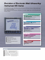
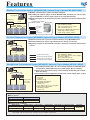
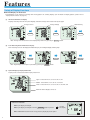

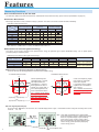
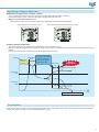
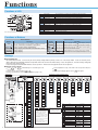
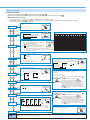
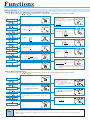
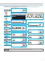
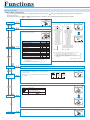
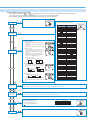

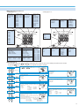
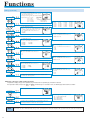
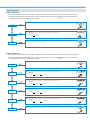
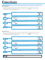
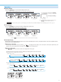

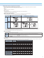
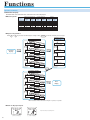


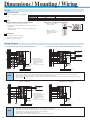
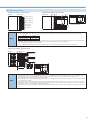
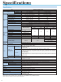

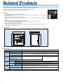
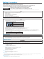


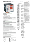
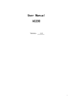
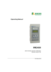


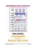

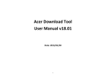
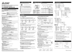
![自動力率調整器 QCシリーズ [EH792e]](http://vs1.manualzilla.com/store/data/006626228_2-037c7e1544b3dc47c415e1572b23653b-150x150.png)