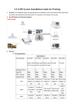
1
Energy Measuring Unit Model EMU4-BD1-MB EMU4-HD1-MB User’s Manual (Details) Safety precautions Thank you for purchasing the Energy Measuring Unit. ・ This manual describes setup and usage for the Energy Measuring Unit. Before using the product, please read this manual carefully to ensure correct use. Especially, in the case of where this unit is to be installed, please read “1. Precautions for Use” to ensure correct use. ・ Make sure that the end users read this manual and then keep the manual in a safe place for future reference. ・ Make sure to deliver this manual to the end-user. ・ If you are considering using this unit for special purpose such as nuclear power plants, aerospace, medical care or passenger vehicles please refer to our sales representative.(For details, please see at the end of this manual.) ・ Notations in this manual Use the following marks in this manual. Mark Meaning of the icons Danger Indicates that incorrect handling may result in death or severe injury, ignoring this marking. Caution Indicates that incorrect handling may result in injury or property damage, ignoring this marking. Supplement Indicates that precautions to avoid a malfunction and to work the unit properly. Indicates that the pages described that related matters. ・ Checking package contents This following items for this device and included in package. Check that no items are missing. (1) Energy Measuring unit x1 (2) User’s Manual (Digest) x1 This unit cannot be used for deal and proof of electric energy measurement stipulated in the measurement law. Please use the certified watt-hour meter to be used for deal and proof of electric energy measurement stipulated. Features [EMU4-BD1-MB] ・ This Energy Measuring unit can measure various types of electric quantity such as voltage, current, electric power and electric energy. ® ・ The measured data can be sent to the high-end device, such as a monitoring device by MODBUS RTU communication function. [EMU4-HD1-MB] ・ This Energy Measuring unit can measure various types of electric quantity such as voltage, current, electric power and electric energy. ® ・ The measured data can be sent to the high-end device, such as a monitoring device by MODBUS RTU communication function. ・ This Energy Measuring unit has one external input terminal, which can switch between pulse input and contact input. Production quantity and water, gas, air (other than electricity) can be measured in the pulse input setting. Monitoring of condition and alarm, measurement of operating time and electric energy during operation can be done in the contact input setting. ® MODBUS is registered trademarks of Schneider Electric SA. (1/67) Table of Content Safety precautions ................................................................................................................................................................. 1 Features ................................................................................................................................................................................... 1 Table of Content...................................................................................................................................................................... 2 1. Precautions for Use ........................................................................................................................................................... 3 Precautions for Operating Environment and Conditions .................................................................................................... 3 Matters concerning the precaution before use.................................................................................................................... 3 Installation and Wiring Precautions...................................................................................................................................... 3 Precautions for Use .............................................................................................................................................................. 4 Maintenance Precautions..................................................................................................................................................... 5 Storage Precautions ............................................................................................................................................................. 5 Disposal Precautions ............................................................................................................................................................ 5 About packaging materials and this manual........................................................................................................................ 5 2. Disclaimer............................................................................................................................................................................ 6 3. Name and function of each part....................................................................................................................................... 6 4. Attaching and removing the unit ..................................................................................................................................... 8 5. Procedure for wiring .......................................................................................................................................................... 9 Wiring for EMU4-BD1-MB .................................................................................................................................................... 9 Wiring for EMU4-HD1-MB.................................................................................................................................................... 9 6. Operating mode................................................................................................................................................................ 12 7. Setting method ................................................................................................................................................................. 13 Procedures for setting......................................................................................................................................................... 13 Setting menu 1: Phase wire system, primary voltage, sensor type, primary current, demand time, etc. ...................... 15 Setting menu 2: MODBUS® communication ..................................................................................................................... 19 Setting menu 3: Contact / pulse input/output, equivalent CO2, harmonic, operating time, etc. ...................................... 22 Setting menu 4: Upper / lower limit alarm setting, alarm delay time ,alarm reset, etc. ................................................... 23 Setting menu 5: Setting related to logging unit.................................................................................................................. 25 Confirmation menu 1 - 5: Confirmation of setting values in setting menu 1 - 5............................................................... 25 Initialization of related items by change of setting............................................................................................................. 26 Clock setting and logging data clear .................................................................................................................................. 27 Change of date format........................................................................................................................................................ 28 How to use test mode......................................................................................................................................................... 29 Test menu 1: Discrimination support function for improper connection ........................................................................... 30 Test menu 2: Communication test...................................................................................................................................... 42 Test menu 3: Pulse output test........................................................................................................................................... 43 Test menu 4: Alarm output test........................................................................................................................................... 43 8. Operation ........................................................................................................................................................................... 44 Operation procedure in operating mode............................................................................................................................ 44 Measured item indication in operating mode..................................................................................................................... 46 Display examples in operating mode................................................................................................................................. 48 How to use upper/lower limit alarm function...................................................................................................................... 50 Operations of alarm reset ................................................................................................................................................... 51 Preset and all data reset..................................................................................................................................................... 52 9. Device operation............................................................................................................................................................... 53 Measured items................................................................................................................................................................... 53 Restrictions of measured data............................................................................................................................................ 55 10. Reference......................................................................................................................................................................... 56 In case you think the unit is in failure ................................................................................................................................. 56 About error number............................................................................................................................................................. 56 After-sales service............................................................................................................................................................... 57 Q&A ..................................................................................................................................................................................... 57 11. Requirement for the compliance with EMC Directives ............................................................................................ 59 12. Specifications ................................................................................................................................................................. 60 Common specifications ...................................................................................................................................................... 60 Specifications of MODBUS® communication .................................................................................................................... 62 13. Option devices................................................................................................................................................................ 63 14. External dimensions...................................................................................................................................................... 66 15. Index................................................................................................................................................................................. 67 16. Customer service ........................................................................................................................................................... 67 (2/67) 1. Precautions for Use Precautions for Operating Environment and Conditions ・ ・ ・ This unit is premised on being used in pollution degree 2* environment. When used in higher pollution degree, protect this unit from pollution on another device side to be incorporated. Over voltage category of measuring circuit in this unit is CAT II*, and that of auxiliary power circuit (MA, MB) is CAT II*. Do not use this product in the places listed below. Failure to follow the instruction may cause malfunctions and a life decrease of product. - Places the Ambient temperature exceeds the range -5 - +55°C. - Places the average daily temperature exceeds 35°C. - Places the Relative humidity exceeds the range 30-85% or places with dewfall. - Vibration and impact exceed the specifications. - Dust, corrosive gas, saline and oil smoke exist. - Places exposed to direct sunlight. - Places exposed to rain or water drop. - Places in strong electromagnetic field or places large amounts of external noise exist. - Places metal fragments or conductive substance are flying. - Altitude exceeds 1000m. < For prevention of electric shock> ・ This unit is designed to be housed within another device for prevention of electric shock. House this unit within the device such as the grounded control panel before use. ・ To prevent persons with little knowledge about electric equipment from electric shock, panel must be taken either following measure. - Lock the panel so that only those who get an education about electric equipment and have sufficient knowledge can unlock, or shut off power supply automatically by opening the panel. - Cover the dangerous part of this unit. (Required protection code is higher than IP2X.) *: For the definition of the pollution degree and the over voltage category, refer to EN61010-1/2010. Matters concerning the precaution before use ・ ・ Use the unit in the specified usage environment and conditions. The setting of this unit (phase system, primary voltage, primary current, and sensor type) is necessary before use it. Installation and Wiring Precautions Make sure to read this manual carefully before Installation and Wiring. Caution <Precautions for Electric work> ・ Any person who is involved in the installation and the wiring of this unit should be fully competent to do this work. ・ Work under the electric outage condition when installing and wiring. Failure to do so may cause electric shock, a failure of the unit, a fire etc. ・ When tapping or wiring, take care not to entering any foreign objects such as chips and wire pieces into this unit. ・ Check the connection diagram when wiring. Wrong wiring may cause failure of the unit, a fire or electric shock. ・ For protection against noise, transmission lines and input/output lines shall not be placed close to or bound together with the power lines and high-voltage lines. ・ The wires to be connected to this unit shall be placed in a duct or fixed together by cramping. If the electric wires are not placed in the duct or cramped together, loosen wires or their movement or careless stretch may cause a breakage of the unit or wire or a malfunction due to poor contact of electric wires. ・ If transmission lines and input/output lines are placed close to or bound together with the power lines and high-voltage lines, keep distance as below between them. Condition Distance Power line 600V or less Other power line 300mm or longer 600mm or longer (3/67) <Connection of terminal block> ・ Strip the wires with proper length. Overlong stripping length may cause short to next wire. Shorter stripping length may cause contact failure. ・ Take care not to short to next terminal by a filament. (Do not plate the wires with solder.) ・ Do not connect three or more wires to one terminal of a terminal block for preventing loose contact and wires dropout. ・ Use appropriate size of electric wires. If inappropriate size of electric wire is used, it may cause a fire due to generated heat. ・ Circuits connected to a auxiliary power circuit (MA, MB) need to be used the over current protection device (fuse, circuit breaker, etc.) to prevent shorting connecting wires. (Select an appropriate rating to prevent burnout of the wires.) ・ Tighten the screw within the specified torque. Over tightening can damage the screw and/or terminal. ・ After tightening the screws, be sure to check all the screws tightened. Loose screw may cause malfunction of the unit, a fire or electric shock. ・ Be sure to attach the terminal cover to prevent electric shock. ・ Do not directly touch any conductive part of the unit. Doing so can cause electric shock, failure or malfunction of the unit. ・ If the wires connected to this unit are strongly pulled off, it may cause a malfunction or a breakage to the unit or the wire. <Connection with the current sensor> ・ When using this product, make sure to use it in combination with current sensor (EMU-CT50 / CT100 / CT250 /CT400 /CT600, EMU2-CT5 and EMU2-CT5-4W). This product cannot connect with the secondary side (5A) of current transformer. Please not to exceed the rating of this product for input of current sensor. For further details, please refer to current sensor manual to maintain the functionality and the accuracy of this product. ・ The dedicated current sensor (EMU-CT50/CT100/CT250/CT400/CT600) is used only for low voltage circuit. It cannot be used for a high voltage circuit. EMU2-CT5 and CT5-4W should be used with the secondary side (5A) of transformer transfixed. If it is connected with a high-voltage circuit by mistake, it may cause a burnout of the device and a fire. It is critically dangerous. For the allowable maximum voltage of current sensor, refer to “13. Option devices” “(1) Specifications” in this manual. ・ The dedicated current sensor has a polarity (directionality). Be careful about it when installing the unit. <Connection of frame GND terminal> ・ Do not exceed the specified voltage when doing an insulation resistance test and a commercial frequency withstand voltage test. Do not connect to frame GND terminal during the insulation resistance test and pressure test. ・ Use the crimp-type terminal appropriated for the size of electric wires. If inappropriate crimp-type terminal is used, a wire breakage or a contact failure may occur, which may cause a device malfunction, a failure, a burnout or a fire. ・ Frame GND terminal must be grounded according to the D-type ground (ground resistance is not exceed 100Ω). Precautions for Use ・ ・ ・ This unit cannot be used for deal and proof of electric energy measurement stipulated in the measurement law. Before operating the product, check that active bare wire and so on does not exist around the product. If any bare wire exists, stop the operation immediately, and take an appropriate action such as isolation protection. In the event of a power outage during the setting, the unit is not set correctly. Please set again after power recovery. Danger ・ Do not touch the live part. It may cause electric shock, electric burn injury or damage of the device. ・ Work under the electric outage condition when installing and wiring. Caution ・ Do not disassemble or modify this unit. It may cause failure, malfunction, injury or fire. ・ Use this unit within the ratings specified in this manual. If it is used outside the ratings, it may cause not only malfunction or failure but also fire burnout. (4/67) Maintenance Precautions ・ Use a soft dry cloth to clean off dirt of the unit surface. Do not let a chemical cloth remain on the surface for an extended period of time nor wipe the surface with thinner or benzene. ・ Check for the following items to use this unit properly for long time. (1) Daily maintenance (a) No damage on this unit (b) No abnormality with LCD indicators (c) No abnormal noise, smell or heat (2) Periodical maintenance (Once every 6 months to 1 year) - No looseness with installation and wire connection Caution Do periodical maintenance under the electric outage condition. Failure to do so may cause electric shock, failure of the unit or a fire. Tighten the terminal regularly to prevent a fire. Storage Precautions ・ To store this unit, turn off the power and remove wires, and put it in a plastic bag. ・ For long-time storage, avoid the following places. Failure to follow the instruction may cause a failure and reduced life of the unit. - Places the Ambient temperature exceeds the range -10 - +60°C. - Places the average daily temperature exceeds 35°C. - Places the Relative humidity exceeds the range 30-85% or places with dewfall. - Vibration and impact exceed the specifications. - Dust, corrosive gas, saline and oil smoke exist. - Places metal fragments or conductive substance are flying. - Places exposed to rain, water drop or direct sunlight. Disposal Precautions When disposing of this unit, treat it as industrial waste. About packaging materials and this manual For reduction of environment load, packaging materials are produced with cardboard, and this manual is printed on recycled paper. (5/67) 2. Disclaimer ‧ ‧ It is prohibited to reprint or copy all contents of this document in any form without our permission. The contents of this document will be updated to follow revisions to software and hardware, however under unavoidable circumstances it may not be synchronized. 3. Name and function of each part ・ Name of each part (1) EMU4-BD1-MB Frame GND terminal Voltage input terminals Power supply terminals Sign and function of the terminal block Terminal symbols LCD display P1, P2, P3 Operation button Current input terminals Connect the voltage input wire for the measuring circuit. Frame GND (FG) Connect to ground (D type ground). MA, MB Auxiliary power Connect the auxiliary power supply. 1k, 1L, 3k, 3L Input current Connect the secondary output of the dedicated current sensor connected to the measurement circuit’s current wire. 485+,485- MODBUS® communication Connect the communication ( MODBUS® RTU). wire SLD Connect to ground (D type ground). Ter Connect with “485- “terminal (the unit at end of the link) P.11. Communication terminals (MODBUS® RTU) Sign and function of the terminal block Frame GND terminal Terminal symbols Power supply terminals LCD display Operation button Function Description P1/P1, P2/P0, P3/P3, NC/P2 Input voltage Frame GND (FG) Connect to ground. (D-type ground) MA, MB Auxiliary power Connect the auxiliary power supply. 1k, 1L, 2k, 2L, 3k, 3L Input current Connect the secondary output of the dedicated current sensor connected to the measurement circuit’s current wire. 485+, 485- MODBUS® communication Connect the communication (MODBUS® RTU). Connect the voltage input wire of the measuring circuit. wire SLD Connect to ground. (D-type ground) Ter Connect with “485-“ terminals (the unit at end of the link) P.11. X1, COMX Pulse input/ contact input Connect pulse input/contact input wires. Y1, COMY Pulse output/ contact output Connect pulse output/contact output wires. Contact/ pulse output terminals Current input terminals Description Input voltage (2) EMU4-HD1-MB Voltage input terminals Function Contact/ pulse input terminals Communication terminals (MODBUS® RTU) (6/67) ・ Back view IEC rail fixture ・ Function of operation buttons Control buttons have many functions as below. (How to change mode page 12.) Meaning of symbol: ○ (Press), □ (Press more than 1 sec), ◎ (Press more than 2 sec), ― (Press both at the same time) Operation Name of Button Event Mode SET -/RESET +/PHASE DISP ○ ○ DISP button +/PHASE button -/RESET button ○ ◎ ◎ ◎ Operating Mode Contact display SET button Integrated value display Menu display Clear alarm (at alarm generation display with alarm keeping) Transition to confirmation mode Transition to setting mode ◎ Clear contact latch ◎ ◎ ◎ ◎ Transition to preset display ◎ Transition to reset display of all data ○ ○ (□) ○ (□) ○ (□) ○ (□) ○ Setting mode / Setting display Setting mode / Confirmation Confirmatio mode n mode / Setting display ○ □ ○ ○ □ Confirmatio n display of setting reflection Change measured items Change phase Change harmonic order (at harmonic display) ○ ○ ○ ◎ ◎ Enter setting menu Moving up or down of menu number (Move at fast speed when pressing more than 1sec) Change of setting items (forward) Transition to setting menu number (at final setting item) Moving up or down of setting value (Move at fast speed when pressing more than 1sec) Change setting items (backward) Transition to setting menu number (at beginning setting item) Go back to setting menu Change setting items (forward) Transition to setting menu number (at final setting item) Change setting items (backward) Transition to setting menu number (at beginning setting item) Transition to setting menu At "END" display, memorize changed setting and transition to operating mode At "CANCEL" display, annul changed setting and transition to operating mode Moving up or down of setting value Reset setting values to factory default (only effective at CANCEL display) ・ Functions of LCD 2 3 4 5 No. 1 2 3 4 5 1 Indicator Measured v alue Measured item Communication Energy Measurement Setting Description Display measured v alue digitally. Display measured item displayed on indicator 1. Light when connecting comm unication unit. Light when measuring electric energy Indicator lights on setting m ode. Indicator lights on confirmation mode. (7/67) 4. Attaching and removing the unit Caution Any person who is involved in the installation and the wiring of this unit should be fully competent to do this work. There are two installation methods, surface mounting and panel mounting ・ Surface mounting (1) How to attach to the IEC rail Applicable IEC rail Attaching Removing (1) Pull IEC rail fixture downward. (2) Catch IEC rail (2) Pull the unit More than 7.3 (3) Push in (1) Hold the unit and pull IEC rail fixture downward. (4) Push the IEC rail fixture upward. ・ Plate mounting (1) Screw mounting Dimensions of hole panel Attaching Outline of the unit Attach the plate by using 2 screws. Tightening torque: 0.63N・m Mounting screws Plate Recommended screws cross recessed head screw with captive washer and flat washer M3×10 2pcs (2) Screw mounting (When using the attachment for panel mounting) Dimensions of hole panel Outline of the unit Attaching Attach the plate by using 2 screws, then install the attachment on the plate. Tightening torque: 0.63N・m Screws for panel mounting attachment Mounting screws Attachment for panel mounting Plate *Please screw up the panel mounting attachment where there are high levels of vibration. *The screws (mounting screws and screws for panel mounting attachment) are supplied with panel mounting attachment. (8/67) 5. Procedure for wiring Wiring for EMU4-BD1-MB 1P3W/3P3W (for low voltage circuit) 1P2W (for low voltage circuit) Power source side 1 2 Power source side 1 1 EMU-CT*** model split current sensor (50/100/250/400/600) 3 3 N 2 EMU-CT*** model split current sensor (50/100/250/400/600) K K L L K RS485 (MODBUS ®) RS485 (MODBUS®) Load side L Load side 3P3W (for high voltage circuit) Power source side 1 2 3 Current transformer ***/ 5A 5A current sensor EMU2-CT5 K RS485 (MODBUS®) L K L 5A current sensor cable EMU2-CB-Q5B Load side Wiring for EMU4-HD1-MB 1P3W/3P3W (for low voltage circuit) 1P2W (for high voltage circuit) Power source side 1 2 Power source side 1 1 3 3 N 2 EMU-CT*** model split current sensor (50/100/250/400/600) Current transformer ***/ 5A Contact/ pulse output Contact/ Puls e input 5A current sensor EMU2-CT5 K K L Contact/ pulse output Contact/ Pulse input K L Load side 5A current sens or c able EMU2-CB-Q5B RS485 (MODBUS®) L Load side (9/67) RS485 (MODBUS ®) 3P3W (for high voltage circuit) 3P4W (for high voltage circuit) Power source side 1 Power source side 3 2 1 3 2 N Current transformer ***/ 5A Current transformer ***/ 5A 5A current s ensor EMU2-CT5 Contact/ pulse output Contact/ Pulse input K L L 5A current s ensor cable EMU2-CB-Q5B L Load side Contact /pulse output RS485 (MODBUS®) Contact /pulse input K L K Caution 5A current sensor EMU2-CT5-4W K K L 5A current sensor cable EMU2-CB-Q5B-4W Load side RS485 (MODBUS®) ・ For protection against noise, transmission lines and input/output lines shall not be placed close to or bound together with the power lines and high-voltage lines. Keep distance as below between them. (except for the terminal block) Condition distance Power line 600V or less 300mm or longer Other power line 600mm or longer ・ For the actual usage, connect the frame GND terminal to ground (D-type ground). Connect it directly to the ground terminal. ・ Do not connect to frame GND terminal during the insulation resistance test and pressure test. ・ Use appropriate crimp-type terminal. Appropriate crimp-type terminal is as below. ・ Use electric wires as below, and tighten the terminal screws by the torque as below. [EMU4-BD1-MB] Auxiliary power, voltage input terminals Current input, input and output terminals Applicable wire AWG24 - 16 (Single / Stranded) AWG22 - 14 (Single / Stranded) Tightening torque 0.8 N・m 0.5~0.6N・m Recommended crimp-type terminal For M3 screw of external diameter below 5.6mm For M3 screw of external diameter below 5.6mm Applicable wire AWG26 - 14 (Single / Stranded) AWG22 - 14 (Single / Stranded) Tightening torque 0.8~1.0N・m 0.5~0.6N・m Recommended crimp-type terminal For M3.5 screw of external diameter below 5.6mm For M3 screw of external diameter below 5.6mm [EMU4-HD1-MB] Auxiliary power, voltage input terminals Current input, input and output terminals ・ Make sure that before connecting the cable, the orientation of the current sensor is correct for attachment. K to L is the correct direction. K: power source side, L: load side ・ EMU-CT50/100/250/400/600 is used only for low voltage circuit. (Maximum voltage: 460V) It cannot be used for a high voltage circuit. EMU2-CT5 and EMU2-CT5-4W should be used with the secondary side (5A) of transformer transfixed. If they are used for the circuit directly, they should be used under 200V. (Maximum voltage: 260V) ・ Maximum voltage of the circuit connected to this unit directly is 260V for EMU4-BD1-MB, or 277 / 480V for EMU4-HD1-MB. For the circuit over this voltage, use the transformer. Using the transformer, primary voltage is configurable up to 6600V. ・ For MODBUS® communication wiring, recommended to have the extra length wires about 200mm (When extended to B / NET transmission from MODBUS® communication, use of MODBUS® communication wiring is possible). ・ When screwing the terminals at both ends of the terminal block, be careful not to touch the projection of the terminal block cover. ・ In case using external input and/or external output, refer to the following. External input:For the case of contact input External input: For the case of pulse input No-voltage a-contact Use an appropriate type for 5V DC 7mA switching. No-voltage a-contact Use an appropriate type for 5V DC 7mA switching. Trans mitter External output:For the case of contact output External output: For the case of pulse output No-voltage a-contact 35V DC 75mA or, 24V AC 75mA (power factor : 1) No-voltage a-contact 35V DC 75mA or, 24V AC 75mA (power factor : 1) Counter Relay (10/67) ・ System configuration example of MODBUS® communication RS-232 or USB ® MODBUS (RS-485) 120Ω 120Ω OR PLC Unit PC Unit Unit Maximum connectable devices: 31 devices ® ・Connection of MODBUS communication terminals: page 62.) 1. Use the twisted shielded pair cable for transmission lines.(Recommended cable ® 2. Connect the termination resistances (120Ω) to both ends of the devices connected the MODBUS transmission line. Termination resistances of 120Ω can be used by short-circuiting “485-” and “Ter” terminals. 3. Connect to ground by using thick wires to decrease impedance. ® 4. MODBUS transmission lines shall not be placed close to or bound together with the high-voltage lines. 5. Ground the “SLD” terminal at one end. (11/67) 6. Operating mode This unit has the operating modes. Switch these modes according to the purposes. The operating mode is displayed immediately after the auxiliary power loading. Mode Function Reference Operating mode Display measured value digitally. It can display the condition of contact input (*1) and present time (*2) other than the present value of the measured values. page 44 Setting mode Set basic setting for phase wire method, primary voltage, primary current, and sensor type and alarm monitoring for alarm output elements. page 13 Confirmation mode Mode to confirm the setting value for each setting item. (The Setting cannot be changed in this mode, so it can be prevented setting change by human error.) In addition, this unit has the test function that can be used for such as set up of an equipment. ・ Discrimination support display for incorrect wiring: Display useful to discriminate for incorrect wiring such as phase angle display of voltage, current. ・ Pulse, Alarm test: Switch pulse output contact and alarm contact without measurement (voltage and current) input. ・ Communication test: Send back fixed numerical data without measurement (voltage and current) input. page 25 page 29 Reset mode / Reset: Integrated values (electric energy, operating time, etc.) can be zeroed. Preset mode Preset: Preset of electric energy and reactive energy. *1: EMU4-HD1-MB only. *2: Only when connecting logging unit. SET + ー SET Press both at the same time for 2 sec End display Operating mode SET Fix change of setting value + SET Present value display - When selecting "End" on the menu Cancel change of setting value Press for 2 sec SET + Setting mode CANCEL display SET DISP page 52 + - Press both at the same time for 2 sec When selecting "End" on the menu Reset mode/ Preset mode Confirmation mode Test mode (12/67) 7. Setting method Procedures for setting Set items such as phase wire system, primary voltage, and primary current in the setting mode to measure and monitor. Under normal use, it shall be sufficient to set the setting menu 1 (Basic setting) only. For details, refer to after the following page. <How to set> (1) Go into the setting mode by pressing both SET and - / RESET at the same time for 2 sec. (2) Determine the setting menu number by pressing + / PHASE or - / RESET . SET . (3) Determine the setting menu number by pressing (4) Set each setting item. (5) After all setting are done, select “End” on the setting menu and press SET . (6) When prompted for End display, select “End” and press SET . Operating mode Setting menu 1 Measurement display End of setting menu Setting menu 2 Basic setting Communication setting ※1 "End" display Fix of setting value "CANCEL" display Cancel of setting value change Phase wire system MODBUS® address Primary voltage (use or non-use of VT) MODBUS® baud rate ※2 Primary voltage (With VT or Direct) MODBUS® parity Transition automatically Factory default MODBUS® stop bit Sensor type ※3 Primary current Example of setting mode display Example of confirmation mode Current demand time Power demand time ※2 For the special voltage (SP) (Not available for 1P3W) ※3 For the special current (SP) Primary voltage (VT voltage) Sensor type Primary special voltage Primary special current Secondary special voltage Caution If you change setting, related setting items and measured data are initialized. Check before change. (13/67) page 26 Procedures for setting ・ Basic operations in setting Function Operation Supplement Choose setting value Press + / PHASE or - / RESET . Press for more than one second to fast-forward confirm setting value Press SET After setting value is confirmed, transition to next item. Go back the previous setting item Press DISP . Go back to setting menu during setting Press SET for one second. . Setting value of the last item before return is effective. Setting mode or confirmation mode Setting menu 3 Setting menu 4 Setting menu 5 Setting menu 6 Input/output setting Alarm setting Logging setting Test mode ※4 ※4 ※9 ※8 Use of upper / lower limit alarm Logging module ID Reset method of contact input Upper / lower limit alarm element Logging data clear confirmation Contact / pulse output Upper / lower limit alarm value Contact / pulse input Test mode ※5 ※6 Unit amount of pulse output Alarm delay time Alarm reset method Equivalent CO2 indication ※7 CO2 conversion factor Harmonic current indication Symbol Behavior Transition from operating mode to setting mode. Harmonic voltage indication ransition from operating mode to confirmation mod Operating time indication No display ※4 Counting method of operating time ※1: On confirmation mode, transition to operating mode. ※2: Transition only when selecting "SP" for "Primary voltage (VT or direct voltage)" on Setting menu 1. (For 3P4W, only special voltage is available when using VT.) ※3: Transition only when selecting "SP" for "Primary current (5A)" on Setting menu 1. ※4: Setting available for EMU4-HD1-MB only. ※5: Transition only when selecting "CO.P." for "Contact/pulse input". ※6: Transition only when selecting "PLS" for "Contact/pulse output". ※7: Transition only when selecting "on" for "Equivalent CO2 indication". ※8: Transition only when connecting logging module. ※9: Not displayed on setting mode. ※10: The following data is not cleared. Electric energy (consumption, regeneration), Reactive energy, Equivalent CO2 (hide), Operation time (hide) When selecting "CO.P."for "Counting method of operating time", operation time is cleared. Operation of control button Press both at the same time for 2 sec "SET" Press for 2 sec "SET" + "-" Select menu number or "End". "+" or "-" Enter each setting display or transition to next item "SET" Press several times Press once Go back to previous setting display. "DISP" Press once Select setting value. "+" or "-" Press several times Transition to "End" display. Memorize changed setting and transition to operating mode. Select "CANCEL". "SET" Press once "SET" Press once "+" or "-" Press once Cancel change of setting value. "SET" Press once Skip other items during setting. "SET" Press for 1 sec Reset setting values to factory default. "DISP" + "-" Press once (14/67) Setting menu 1: Phase wire system, primary voltage, sensor type, primary current, demand time, etc. In this menu, set phase wire system, primary voltage, sensor type, primary current, demand time, etc. In operating mode, press both SET and - / RESET at the same time for more than two seconds to transition to setting mode and enable the following operations. Setting menu SET Choose the setting menu 1. (As shown in the left figure) DISP Set according to the phase wire system for the measured circuit. (1) Phase wire system ・ For EMU4-BD1-MB ・ For EMU4-HD1-MB 3P3: Three-phase 3-wire 1P2: Single-phase 2-wire 1P3: Single-phase 3-wire 3P3: Three-phase 3-wire 3P4: Three-phase 4-wire 1P2: Single-phase 2-wire 1P3: Single-phase 3-wire Supplement: The underlined values are the defaults. (The same shall apply hereinafter.) SET DISP (2) Primary voltage (Use or non-use of VT) If you measure directly (i.e. without VT): →Choose “no” and press SET to transition to (3) Primary voltage (Direct). If you measure with VT: →Choose “yES” and press SET to transition to (4) Primary voltage (VT). no yES Supplement: “VT” means Voltage Transformer. SET DISP <In case you choose “1P3” in (1) Phase wire system> You can use direct measurement only. Setting of primary voltage is skipped and setting is started from (7) Sensor type. Rated voltage between 1- and 2-phase and 2- and 3-phase is 110V, and that between 1- and 3-phase is 220V. Set the direct voltage according to voltage of the measured circuit ・ For EMU4-BD1-MB 110V 220V ・ For EMU4-HD1-MB (3) Primary voltage (Direct) (In case you choose “3P3” or “1P2” in (1) Phase wire system) 110V SET 220V 440V DISP (15/67) (In case you choose “3P4” in (1) Phase wire system) 63.5V/110V 100V/173V 105V/182V 110V/190V 115V/199V 120V/208V 127V/220V 200V/346V 220V/380V 230V/400V 240V/415V 242V/420V 250V/430V 254V/440V 265V/460V 277V/480V Setting menu 1: Phase wire system, primary voltage, sensor type, primary current, demand time, etc. Set the primary voltage of combined VT ・ For EMU4-BD1-MB 440V 690V 1100V 2200V 3300V 6600V SP ・ For EMU4-HD1-MB (4) Primary voltage (with VT) 690V 1100V 2200V 3300V 6600V SP Caution: If there is no values above you want to set to, choose “SP” to enable the special primary voltage and the special secondary voltage. In case you choose “3P4” (three-phase 4-wire system) in (1) Phase wire system, the special voltage is only available. If you choose “SP”, transition to “(5) Special primary voltage”. If you choose the value except for “SP”, transition to “(7) Sensor type”. (In this case, secondary voltage is fixed to 110V.) SET DISP Set the special primary voltage of combined VT. ・ Setting range: 1V to 6600V Default value is 440V (for EMU4-BD1-MB), or 690V (for EMU4-HD1-MB). (5) Special primary voltage Setting of special primary voltage ・ Press + / PHASE or - / RESET to choose the value at flashing digit. ・ Press SET for the setting digit (flashing digit) to shift to lower. ・ Press DISP for the setting digit (flashing digit) to shift to upper. ・ You can set the upper three digit of the value to the range of 1V to 6600V. Caution: In case you set the value except for between 1V and 6600V, indicate the error (E005). When indicating the error, press SETto check the setting values and set the new value again. ・ Press SET at the lowest digit to transition to “(6) Special secondary voltage”. The values set the upper fourth digit and lowers to are rounded down. After setting value flashes three times, transition to “(6) Special secondary voltage”. SET DISP Set the special secondary voltage of combined VT. ・ Setting range: 1V to 220V Default value is 110V (for three phase 3-wire system and single-phase 2-wire system), or 64V (for three-phase 4-wire system). (6) Special secondary voltage Setting of special secondary voltage ・ Press + / PHASE or - / RESET to choose the value at flashing digit. ・ Press SET for the setting digit (flashing digit) to shift to lower. ・ Press DISP for the setting digit (flashing digit) to shift to upper. ・ You can set the value to the range of 1V to 220V. Caution: In case you set the value except for between 1V and 220V, indicate the error (E005). When indicating the error, press SET to check the setting values and set the new value again. ・ Press SET at the lowest digit to transition to “(7) Sensor type”. SET DISP (16/67) Setting menu 1: Phase wire system, primary voltage, sensor type, primary current, demand time, etc. (7) Sensor type Set the type of combined current sensor. If you use direct sensor, choose “dirEct” and press SET to transition to “(8) Primary current (Direct)”. If you use 5A sensor, choose “5A” and press SET to transition to “(9) Primary current (5A sensor)”. dirEct SET 5A DISP (8) Primary current (Direct sensor) Set the primary current of combined CT (for direct sensor). 50A 100A 250A 400A 600A After you choose the value, transition to “(11) Current demand time”. Set the primary current of combined CT (for 5A sensor). SET DISP (9) Primary current (5A sensor) 5A 6A 7.5A 8A 10A 12A 15A 20A 25A 30A 40A 50A 60A 75A 80A 100A 120A 150A 200A 250A 300A 400A 500A 600A 750A 800A 1000A 1200A 1250A 1500A 1600A 2000A 2500A 3000A 4000A 5000A 6000A SP Supplement: If there is no values above you want to set to, choose “SP” to enable the special primary current. If you choose “SP”, transition to “(10) Special primary current”. If you choose the value except for “SP”, transition to “(11) Current demand time”. SET DISP Set the special primary current of combined CT. ・ Setting range: 5A to 6000A (Default: 100.0A) Setting of special primary current ・ Press + / PHASE or - / RESET to choose the value at flashing digit. (10) Special primary current ・ Press SET for the setting digit (flashing digit) to shift to lower. ・ Press DISP for the setting digit (flashing digit) to shift to upper. ・ You can set the value in the range from 5A to 6000A. If the value is less than 10A, you can set upper two digits of it. If the value is 10A or more, you can set upper three digits of it. Caution: In case you set the value except for the range from 5A and 6000A, indicate the error (E005). When indicating the error, press SET to check the setting values and set the new value again. ・ Press SET at the lowest digit to transition to “(11) Current demand time”. SET DISP (17/67) Setting menu 1: Phase wire system, primary voltage, sensor type, primary current, demand time, etc. Set the current demand time. On setting display, “s” means “second” and “M” means “minute”. (11) Current demand time 0s 10s 20s 30s 40s 50s 1M 2M 3M 4M 5M 6M 7M 8M 9M 10M 11M 12M 13M 14M 15M 20M 25M 30M SET DISP Set the electric power demand time. On setting display, “s” means “second” and “M” means “minute”. (12) Electric power demand time SET 0s 10s 20s 30s 40s 50s 1M 2M 3M 4M 5M 6M 7M 8M 9M 10M 11M 12M 13M 14M 15M 20M 25M 30M DISP Setting menu Complete the setting or continue in other menu according to procedures for setting. For procedures for setting, page 13. (18/67) Setting menu 2: MODBUS® communication In this menu, set address, baud rate, parity and stop bit for MODBUS® communication. In operating mode, press both SET and - / RESET at the same time for more than two seconds to transition to setting mode and enable the following operations. Setting menu SET DISP (1) Address for MODBUS® SET Choose the setting menu 2. (As shown in the left figure) Set the address for MODBUS® ・ Available address: 1 to 255 DISP (2) Baud rate for ® MODBUS Set the transmission speed for MODBUS® 2400bps SET 19200bps 38400bps Set the Parity for MODBUS® EVEn non odd DISP (4) Stop bit for ® MODBUS Set the stop bit for MODBUS® 1 SET 9600bps DISP (3) Parity for MODBUS® SET 4800bps 2 DISP Setting menu Complete the setting or continue in other menu according to procedures for setting. For procedures for setting, page 13. (19/67) Setting menu 3: Contact / pulse input/output, equivalent CO2, harmonic, operating time, etc. In this menu, set contact / pulse input/output, equivalent CO2, harmonic, operating time, etc. In operating mode, press both SET and - / RESET at the same time for more than two seconds to transition to setting mode and enable the following operations. Setting menu Choose the setting menu 3. (As shown in the left figure) ・ For EMU4-BD1-MB, choose “3“ and press SET to transition to (9) Operating time indication . ・ For EMU4-HD1-MB, choose “3“ and press SET to transition to the setting below. SET DISP (1) Contact / pulse input Set External input signal. non SET DISP PLS. CO.P. Set the reset method of contact input. Auto HoLd Reset method (2) Reset method of contact input SET Summery (Setting value) Auto-reset (Auto) When contact input turns OFF (open), contact input state also turns OFF (open) automatically. Self-retention (HoLd) Once the device detects contact input ON (close), contact input state keeps ON (close) until retention clear operation even if contact input turns OFF (open). Supplement: In (1) Contact / pulse input, when you choose the value except for “CO.P.”, this setting is skipped. DISP (3) Contact / pulse output Set External output signal. non SET For pulse input, choose “PLS.”. For contact input, choose “CO.P.”. In case you do not set it, choose “non”. PLS. CO.P. DISP (20/67) For pulse output, choose “PLS.”. For contact output, choose “CO.P.”. In case you do not set it, choose “non”. Setting menu 3: Contact / pulse input/output, equivalent CO2, harmonic, operating time, etc. Set the unit amount per pulse of pulse output. Selectable unit amount is as follows depending on the full load power: α x (VT primary voltage) x (CT primary current) Full load power [kW] = 1000 (4) Unit amount of pulse output Selectable unit amount per pulse [kWh/pulse] less than 12 1 Default value 0.1 0.01 0.001 0.001 12 or more and less than 120 10 1 0.1 0.01 0.01 120 or more and less than 1200 100 10 1 0.1 0.1 1200 or more and less than 12000 1000 100 10 1 1 less than 120000 10000 1000 100 10 10 100000 10000 1000 100 100 12000 or more and DISP Single-phase, 2-wire Single-phase, 3-wire Three-phase, 3-wire Three-phase, 4-wire *1: VT primary voltage in single-phase 3-wire system is regarded as 110V. *2: Using direct connection, replace VT primary voltage with direct voltage in calculation above. *3: In three-phase 4-wire system, replace VT primary voltage or direct voltage with phase voltage in calculation above. Full load power [kW] SET α: 1 2 √3 3 120000 or more Supplement: In (3) Contact / pulse output, when you choose the value except for “PLS.”, this setting is skipped. (5) Equivalent CO2 indication Set whether the equivalent CO2 is indicated or not. oFF on (Do not indicate) (Indicate) ・ If you need this indication, choose “on” and press SET to transition to the setting below. ・ If you do not need this indication, choose “oFF” and press SET to transition to (7) Harmonic current indication. SET DISP (6) CO2 conversion factor Set the CO2 conversion factor (Default value: 0.555kg - CO2 / kWh) Setting of CO2 conversion factor ・ Press + / PHASE or - / RESET to choose the value at flashing digit. ・ Press SET for the setting digit (flashing digit) to shift to lower. ・ Press DISP for the setting digit (flashing digit) to shift to upper. ・ You can set the value to the range of 0.000 to 0.999 (kg - CO2 / kWh). ・ Press SET DISP (7) Harmonic current indication SET SET at the lowest digit to transition to (7) Harmonic current indication . Set whether the harmonic current is indicated or not. oFF on (Do not indicate) (Indicate) DISP (21/67) Setting menu 3: Contact / pulse input/output, equivalent CO2, harmonic, operating time, etc. (8) Harmonic voltage indication SET Set whether the harmonic voltage is indicated or not. oFF on (Do not indicate) (Indicate) DISP (9) Operating time indication Set whether the operating time is indicated or not. (Operating time is integrated while this setting is “oFF”.) oFF on (Do not indicate) (Indicate) ・ For EMU4-BD1-MB, choose “oFF” or “on” and press SET to transition to setting menu. ・ For EMU4-HD1-MB, choose “oFF” or “on” and press SET to transition to the setting below. SET DISP (10) Counting method of operating time SET Set the counting method of operating time. A CO.P. (By current) (By contact input) DISP Setting menu Complete the setting or continue in other menu according to procedures for setting. For procedures for setting, page 13. (22/67) Setting menu 4: Upper / lower limit alarm setting, alarm delay time ,alarm reset, etc. In this menu, set the upper / lower alarm, alarm delay time, reset method of alarm clear, etc. In operating mode, press both SET and - / RESET at the same time for more than two seconds to transition to setting mode and enable the following operations. Setting menu Choose the setting menu No. 4. (As shown in the left figure) Caution: For EMU4-BD1-MB, there is no function of setting menu 4, so the display indicates “non” (as shown in the right figure) and go back to setting menu display. SET (“non” indication) DISP (1) Use of upper / lower limit alarm Set the use or non-use of upper / lower limit alarm. oFF on (Do not use alarm) (Use alarm) ・ If you do not use alarm, choose “oFF” and press SET to enter setting menu. ・ If you use alarm, choose “on” and press SET to transition to the setting below. SET DISP (2) Upper / lower limit alarm element Set the measured element applying upper / lower limit alarm to. Upper / lower limit alarm of measured value is available by setting this item. DA upper limit DA lower limit DA (N) upper limit V (L-L) upper limit V (L-L) lower limit V (L-N) upper limit V (L-N) lower limit DW upper limit DW lower limit PF upper limit PF lower limit PULSE upper limit Caution: 1. DA: Current demand, DA(N): N-phase current demand, DW: Electric power demand V (L-L) : Line voltage, V (L-N) : Phase voltage 2. “DA (N)” and “V (L-N)” are selectable in three-phase 4-wire system 3. “PULSE” is only selectable when you choose “Pulse (PLS.)” on (1) Contact / pulse input of setting menu No.3. SET DISP Set the alarm value of upper / lower limit alarm element. Setting range is as follows: Measured element (3) Upper / lower limit alarm value SET Setting range Unit DA upper limit, DA (N) upper limit 0 - 100 (%) of primary current DA lower limit 0 - 100 (%) of primary current A A V (L-L) upper limit, V (L-N) upper limit 0 - 100 (%) of primary voltage V V (L-L) lower limit, V (L-N) lower limit 0 - 100 (%) of primary voltage V DW upper limit -100 - 0 - 100 (%) of full load power W DW lower limit -100 - 0 - 100 (%) of full load power W PF upper limit -50 - 100 - 50 (%) % PF lower limit -50 - 100 - 50 (%) % PULSE upper limit 1 – 999999 (Default value is 100000) DISP For operation of alarm value setting, refer to next section. (23/67) Setting menu 4: Upper / lower limit alarm setting, alarm delay time ,alarm reset, etc. Operations in alarm value setting display are as follows: Setting of “Upper / lower limit alarm value” ・ Press + / PHASE or - / RESET to choose the value at flashing digit. ・ Press SET for the setting digit (flashing digit) to shift to lower. ・ Press DISP for the setting digit (flashing digit) to shift to upper. ・ Setting range is different for each alarm element. (refer to previous section) Caution: In case the value is set to outside-set-value, indicate the error (E005) When indicating the error, press SETto check the setting values and set the new value again. ・ Press SET at the lowest digit to transition to (4) Alarm delay time . (4) Alarm delay time Set the delay time from fulfilling alarm occurring condition. Set the alarm delay time if you want to avoid the alarm caused by such as instant overload and noise. Once setting, the alarm does not occur unless the time of exceeding the upper / lower limit alarm value is over the specified delay time. In setting display, “s” means “second” and “M” means “minute”. 0s 5s 10s 20s SET 30s 40s 50s 1M 2M 3M 4M 5M DISP Set the alarm reset method in alarm occurrence. (5) Alarm reset method Alarm reset method Summery (For details, refer to page 42) (Setting value) SET Auto-reset (Auto) Reset the alarm automatically when alarm occurring condition is gone. Self-retention (HoLd) The alarm is held even after alarm occurring condition is gone. Button operation is necessary to clear the alarm. DISP Setting menu Complete the setting or continue in other menu according to procedures for setting. For procedures for setting, page 13. (24/67) Setting menu 5: Setting related to logging unit In this menu, set the logging unit ID or logging data clear. In operating mode, press both SET and - / RESET at the same time for more than two seconds to transition to setting mode and enable the following operations. Setting menu Choose the setting menu 5 (As shown in the left figure.) Caution: When the logging module is not connected, the display indicates “non” (as shown in the right figure) and go back to setting menu SET (“non” indication) DISP (1) Logging module ID Set the basic measuring unit number memorized in the logging unit. ・Available ID: 1 to 255 SET DISP (2) Logging data clear confirmation SET Clear the logging data. no yES (Do not clear data) (Clear data) DISP Setting menu Complete the setting or continue in other menu according to procedures for setting. For procedures for setting, page 13. Confirmation menu 1 - 5: Confirmation of setting values in setting menu 1 - 5 In operating mode, press SET for more than two seconds to transition to confirmation mode and enable operation. Transition of display and operation is as same as those of setting menu 1 - 5. For setting menu 1 - 5, pp.15 - 25 (Caution: Change of setting is not available in confirmation mode.) (25/67) Initialization of related items by change of setting Logging date clear confirmation Logging ID Menu 5 Alarm reset method Alarm delay time Upper/lower limit alarm value Upper/lower limit alarm element Use of upper/lower limit alarm Operating time measured item setting Operating time indication setting Menu 4 Harmonic voltage indication setting Harmonic current indication setting Equivalent CO2 setting With or without CO2 indication Pulse output unit Contact/pulse output Contact reset status Contact/pulse input Modbus stop bit Modbus parity Modbus address Current demand time Electric power demand time Primary current (Special primary current) Sensor type Secondary voltage Primary voltage (Special primary voltage) Direct voltage Use of VT Phase wire system Setting item Modbus baud rate Changed setting value Menu 2 Menu 3 Menu 1 Phase wire system Menu 1 Use of VT Direct voltage Primary voltage (Special primary voltage) Secondary voltage Sensor type Primary current (Special primary current) Electric power demand time ● ● ● ● ○ ○ ○ Modbus address Modbus baud rate Modbus parity Modbus stop bit Contact/pulse input Contact reset status Contact/pulse output Menu 3 Initialized item Menu 2 Current demand time Pulse output unit With or without CO2 indication Equivalent CO2 setting Harmonic current indication setting Harmonic voltage indication setting Operating time indication setting Operating time measured item setting Menu 5 Menu 4 Use of upper/lower limit alarm Upper/lower limit alarm element Upper/lower limit alarm value ○ ○ ○ ○ ○ ○ ○ ○ ○ ○ ○ ○ ○ ○ ○ ○ ○ ○ ○ ○ ○ □ □ □ ○ Alarm delay time Alarm reset method Logging ID Logging date clear confirmation Symbol Meaning ○ Initialized ● Change to default value corresponding to phase wire system □ None Initialized when the upper limit of pulse count is set and input method is changed from pulse to contact. Not initialized All settings are reset to factory default by the following operation. Settings are only initialized. Integrated values (such as electric energy, reactive energy and operating time) are not changed. Enter CANCEL display in setting mode and operate as follows to initialize all settings. For entering CANCEL display, refer to procedures for setting. ( page 13) Setting mode Initialization completed Press both DISP and - / RESET at the same time for 2sec. CANCEL display Measurement display (26/67) Clock setting and logging data clear When connecting logging unit, you can set the clock of it. On the date indication in operating mode, press both + / PHASE and - / RESET at the same time for more than two seconds to transition to clock setting and enable the following operations. *Caution: The date is not indicated in operating mode when the logging unit is not connected. Clock setting (Year) Set “Year”. Setting range: 2000 to 2099 SET DISP Clock setting (Month) Set “Month”. Setting range: 01 (January) to 12 (December) SET DISP Clock setting (Hour) Set “Hour”. Setting range: 00 to 23 SET DISP Clock setting (Minute) Set “Minute”. Setting range: 00 to 59 SET DISP Logging data clear confirmation Confirm logging data clear. “no” “yES” (Do not clear data) (Clear data) ・ If you do not clear logging data, choose “no” and press SET to enter date indication (operating mode). ・ If you clear logging data, choose “yES” and press SET to transition to below setting. Caution: If you choose “no” (i.e. do not clear data), the clock setting is not changed. SET DISP Final confirmation Confirm logging data clear finally. “no” “yES” (Do not clear data) (Clear data) ・ If you do not clear logging data, choose “no” and press SET to enter date indication (operating mode). ・ If you clear logging data, choose “yES” and press SET to transition to below setting. Caution: If you choose “no” (i.e. do not clear data), the clock setting is not changed. If you choose “yES” (i.e. clear data) here, logging data is cleared, and at the same time, clock setting is changed. (27/67) Change of date format In date format setting, you can choose from “YYYY.MM.DD”, “MM.DD.YYYY” or “DD.MM.YYYY” format. On the date indication in operating mode, press + / PHASE for more than two seconds to transition to date format setting and enable the following operations. *Caution: The date is not indicated in operating mode when the logging unit is not connected. Date indication (YYYY.MM.DD) Set the date format. YYYY.MM.DD DD.MM.YYYY MM.DD.YYYY Press “+ / PHASE” for more than 2sec Date format setting (MM.DD.YYYY) Set the date format to “MM.DD.YYYY” format. If you want to change to the other format, go back to date indication and then change format. The display transitions to “MM.DD.YYYY” format indication (as shown in the left figure). One second later, it transitions to date indication (as shown in the right figure) automatically. Date indication (MM.DD.YYYY) Press “+ / PHASE” for more than 2sec Date format setting (DD.MM.YYYY) Set the date format to “DD.MM.YYYY” format. If you want to change to the other format, go back to date indication and then change format. The display transitions to “DD.MM.YYYY” format indication (as shown in the left figure). One second later, it transitions to date indication (as shown in the right figure) automatically. Date indication (DD.MM.YYYY) Press “+ / PHASE” for more than 2sec Date format setting (YYYY.MM.DD) Set the date format to “YYYY.MM.DD” format. If you want to change to the other format, go back to date indication and then change format. The display transitions to “YYYY.MM.DD” format indication (as shown in the left figure). One second later, it transitions to date indication (as shown in the right figure) automatically. (28/67) Date indication (YYYY.MM.DD) How to use test mode Test mode has the functions which you can utilize in such as the launch of equipment. The functions in test mode are as follows: Test menu Details 1. Discrimination support function for improper connection Indicate phase angle of current and voltage, electric power, voltage and current of each phase. You can discriminate easily whether the input connection for measurement (voltage and current) is proper or not by checking each indicated values. 2. Communication test For the device with communication function, it can send back the fixed numerical data without the input of measurement (voltage and current). Use for such as the opposing test to host system. 3. Pulse output test For EMU4-HD1-MB, you can check the pulse output without the input of measurement (voltage and current). Use for such as the check of the connection to the receiving device. 4. Alarm output test For EMU4-HD1-MB, you can check the alarm output without the input of measurement (voltage and current). Use for such as the check of the connection to the receiving device. ・ How to test (1) Press SET for two seconds to enter confirmation mode. (2) Press + / PHASE or - / RESET to choose confirmation menu 6. (As shown in the right figure) (3) Press SET to enter test mode (4) Test for the each menu. (Confirmation menu 6) ・ Diagram for test mode Confirmation menu 6 Return to the test menu by pressing SET for more than 1 second at all test mode. SET Test mode Test menu End + / PHASE Test menu 1 (Discrimination for improper connection) - / RESET + / PHASE Test menu 2 (Communication test) - / RESET - / RESET SET + / PHASE Test menu 4 + / PHASE - / RESET (*) (*): Restart Operation mode (29/67) Test menu 3 (Pulse output test) (Alarm output test) - / RESET + / PHASE Test menu 1: Discrimination support function for improper connection In configuration mode, choose menu “6” to enter test mode. (You cannot enter from setting mode.) In test mode, the following operations can be possible. Test menu Choose the test menu 1. (As shown in the left figure) Indicate the phase angle, electric power, voltage and current. <Example for three-phase 4-wire> + / PHASE + / PHASE SET + / PHASE Phase angle (Voltage, phase 2N) Phase angle (Voltage, phase 1N) SET + / PHASE + / PHASE Phase angle (Current, phase 1) + / PHASE Phase angle (Current, phase 1) + / PHASE Electric power (phase 1) + / PHASE Electric power (phase 2) SET Electric power (phase 3) + / PHASE + / PHASE Voltage (phase 1N) + / PHASE Voltage (phase 3N) Voltage (phase 2N) + / PHASE SET + / PHASE Current (phase 1) + / PHASE Current (phase 2) SET *Press SET Phase angle (Current, phase 1) + / PHASE SET (1) Discrimination support function for improper connection Phase angle (Voltage, phase 3N) to transition to next element from each display. (30/67) Current (phase 3) Test menu 1: Discrimination support function for improper connection Indicate the phase angle, electric power, voltage and current. <Example for three-phase 3-wire> + / PHASE + / PHASE Phase angle (Voltage, phase 12) Phase angle (Voltage, phase 23) SET + / PHASE + / PHASE Phase angle (Current, phase 3) Phase angle (Current, phase 1) SET + / PHASE + / PHASE Electric Power (phase 1) Electric Power (phase 3) + / PHASE SET (1) Discrimination support function for improper connection + / PHASE + / PHASE Voltage SET + / PHASE + / PHASE + / PHASE Current SET Press “SET” for more than 1sec *Press SET to transition to next element from each display. ・ About phase angle The phase angle is indicated in a clockwise direction from V12, as baseline (0 degree). V23 ∠V23 : Phase angle between V23 and V12 ∠I1 : Phase angle between I1 and V12 ∠I3 : Phase angle between I3 and V12 I3 ∠V23 ∠I1 I2 ∠I3 V12 I1 ・ Display example of discrimination support function for improper connection For display examples for each connection pattern, pp. 32 - 41 Test menu <If you continue other test menu> → Choose other test menu number and press SET . <If you finish the test mode> → Choose “End” and press SET to return to operating mode. (31/67) Test menu 1: Discrimination support function for improper connection ■Display example of discrimination support function for improper connection Display example (Connection example for three-phase 3-wire) No. At the average current (V12=V23、I1=I3) Power factor (Input) ∠V12 1 ∠V23 1 1 0 300 1 1 0 60 1 Delayed 0.866 Delayed 0.707 0 240 30 270 W3 V12 V23 V31 I1 I2 I3 1 2 3 K 1K 1L 3K 3L P1 P2 P3 L V12=V23=V31 W 1=W 3 I1=I2=I3 L U 315 165 45 180 60 210 255 135 165 45 180 60 v u v V Connection between P1 and P2 are reserved. 1 2 K W1=Negative value 3 1K L 1L K V12=V23=V31 90 120 u V U 300 75 240 I1=I2=I3 3K L W3=Positive value U V U V 0 120 210 240 P1 u P2 v P3 Connection of VT side "1"is reversed. 1 2 3 0 300 0 300 0 300 255 135 165 225 180 240 210 300 255 315 225 345 240 0 270 30 300 60 315 75 225 105 240 120 300 315 150 180 195 1K L 1L K V12=V23<V31 I1=I2=I3 3K L W3=Positive value 3L U u V U v P1 u P2 V v P3 Connection of CT on side "1" is reversed. 1 2 3 K W1=Negative value 1K L V12=V23=V31 270 240 270 W1=Negative value 90 120 3L u v K Delayed 0.866 Delayed 0.707 Forward 0.707 Forward 0.866 5 225 W1 Wiring W 1<W 3 Delayed 0.866 Delayed 0.707 Forward 0.707 Forward 0.866 4 345 60 Delayed 0.866 Delayed 0.707 Forward 0.707 Forward 0.866 3 ∠I3 Current display K Delayed 0.866 Delayed 0.707 Forward 0.707 Forward 0.866 2 ∠I1 Voltage display W 1>W 3 Delayed 0.866 Delayed 0.707 Forward 0.707 Forward 0.866 1 Electric power display Phase angle display Forward 0.707 Forward 0.866 Normal status Indicates improper connection I1=I3<I2 W 1=W 3=0 W1=Positive value W3=Negative value W1=Negative value W3=Negative value W1=0 W3=Negative W1=Positive value W3=Negative value 3K L W3=Positive value 3L V U u v u P1 V v P3 U W1=Negative value W3=Positive value 1L K P2 CT side "1" and "3" are swapped. 1 2 3 1K K 1L L V12=V23=V31 I1=I2=I3 3K K 3L L U V U V u v u P1 v P3 P2 Connection of VT's terminals in order of P2, P3, P1 to measuring instrument's terminals P1, P2, P3. 1 2 K 3 1K L V12=V23=V31 (32/67) I1=I2=I3 1L K 3K L 3L U u V U v u V v P1 P2 P3 Display example (Connection example for single-phase 3-wire) Indicates improper connection Connection At the average current (V12=V23、I1=I3) No. Norma l status 1 Power factor (Input) Phase angle display ∠V12 ∠V23 ∠I1 ∠I3 315 135 Forward 0.707 Forward 0.866 1 330 1 180 1 0 0 0 0 0 180 Delayed 0.866 Delayed 0.707 Forward 0.707 Forward 0.866 4 1 1 Delayed 0.866 Delayed 0.707 0 V23 V31 I1 I2 I3 1 2 Current Connecting diagram CT(sid CT(sid 3 e "1") e "3") 1 2 150 180 30 210 45 225 135 315 150 330 180 0 210 30 225 45 135 315 150 330 180 W 1=W 3 3 L P1 P2 P3 V12=V23<V31 30 225 45 315 315 330 330 0 30 45 45 150 0 180 0 180 180 330 I1=I3 W3= Positive value 225 45 135 315 150 330 P2 P1 P3 I2=0 30 225 45 2 3 1K 1L L 1K 1L 3K 3L K Forward Forward L 3K 3L P1 P2 Connection of P1, P2, P3 terminals of measuring instrument is reversed (P2, P3, P1). 1 2 3 W1= Negative value 1K K I1=I3 P2 P3 P1 V12>V23=V31 I2=0 W3= Positive value 1K 1L 3K 3L L 1L K Forward Forward 3K L 3L P1 P2 P3 Connection of CT side "3" is reversed. W1= Positive value 1 2 3 K V12=V23<V31 I1=I3<I2 P1 P2 P3 W3= Negative value 3K 3L 1K L 3K 3L K Revers Forward e L 1L 3K 3L P1 P2 P3 CT side "1" and "3" are swapped. 2 3 1 W1= Negative value 1K K L I1=I3 V12=V23<V31 P1 P2 P3 I2=0 W3= Negative value 3K 3L 1K 1L 1L K 3K 3L L Forward Forward P1 P2 P3 Connection of P1, P2, P3 terminals of measuring instrument is reversed (P3, P2, P1). W1= Negative value 1 2 3 K I1=I3 P3 P2 P1 V12=V23<V31 0 210 1K 1L 3K 3L P1 P2 P3 P3 0 30 L K 315 210 180 1K 1L 3K 3L Forward Forward 1 V12=V23<V31 0 30 K Connection between P1 and P2 are reserved. W1= Negative value 0 210 135 Delayed 0.866 Delayed 0.707 Forward 0.707 Forward 0.866 5 V12 Voltage I2=0 Delayed 0.866 Delayed 0.707 Forward 0.707 Forward 0.866 3 W3 Current display I1=I3 0 Delayed 0.866 Delayed 0.707 Forward 0.707 Forward 0.866 2 W1 Voltage display K Delayed 0.866 Delayed 0.707 Forward 0.707 Forward 0.866 1 Electric power display I2=0 W3= Negative value 1K 1L 3K 3L Forward Forward 1K L K L 1L 3K 3L P1 P2 P3 (33/67) ■Display example of discrimination support function for improper connection. Display example (connection example for three-phase 4-wire) No. Power factor (input) Indicates improper connection At the average current (V1N=V2N=V3N,I1=I2=I3) Phase angle display ∠V1N ∠V2N ∠V3N ∠I1 ∠I2 ∠I3 Forward 0.707 315 Electric power display W1 W2 W3 Voltage Current display display V1N V2N V3N I1 I2 I3 Wiring 75 195 1 2 3 0 K Forward 0.866 330 1K 1L L 90 210 K 2 L Normal status 2L K 1 0 120 240 0 120 240 Delayed 0.866 30 150 270 Delayed 0.707 45 165 285 W 1=W 2=W 3 V1N=V2N=V3N I1=I2=I3 L U V u v U V u v U u v V 1 315 75 195 Forward 0.866 330 90 210 1 2 3 0 0 120 240 0 120 240 L W 1=W 2=W 3 V1N=V2N=V3N K K 0 240 Delayed 0.866 270 1 W 1=Positive value 45 165 W 2=Negative value W 3=Positive value Forward 0.707 315 W 1=Positive value 75 195 W 2=Negative value W 3=Positive value 330 value 90 210 W 2=Negative value W 3=0 240 120 W 1=Positive value 0 120 240 W 2=Negative value V1N=V2N=V3N W 3=Negative value Delayed 0.866 W 1=Positive value W 2=0 30 150 270 W 3=Negative value Delayed 0.707 W 1=Positive value 45 165 285 W 2=Positive value W 3=Negative value Forward 0.707 75 195 315 Forward 0.866 W 1=0 90 210 330 W 2=Positive value W 3=Negative value 0 240 Delayed 0.866 3 120 120 240 30 Delayed 0.707 165 285 W 1=Negative value 45 W 2=Positive value W 3=Positive value Forward 0.707 135 255 15 P0 P3 P2 3K L 3L U V u P1 v U u V v U u v V P0 P3 P2 Connection between P2 and P3 are reserved. 1 2 3 0 K 1K L 1L lK 2K L 2L K I1=I2=I3 3K L 3L u U V U V U V v u v u v P1 P0 P3 P2 Connection between P1 and P3 are reserved. 1 2 3 0 K 1K L 1L K 2K L I1=I2=I3 2L K 3K L 3L u U V P1 v P0 U V u v U V u v P3 P2 Connection between P1 and P0 are reserved. 2 3 0 1 K 1K Forward 0.866 1 Delayed 0.866 Delayed 0.707 150 270 30 L 1L K 0 330 30 180 300 210 330 60 W 1=Negative value W 2=Positive value V1N<V2N=V3N W 3=Positive value 2K L I1=I2=I3 2L K 3K L 3L U V 90 225 345 105 (34/67) u P1 v P0 U V u v U V u v 3K 3L U u V v U u V v P1 u v P2 U V 2L I1=I2=I3 W 1=Negative value W 2=Positive value W 3=0 150 270 L 2K K W 1=Positive value W 2=Positive value W 3=Negative value W 1=Negative value 0 W 2=Positive value V1N=V2N=V3N W 3=Negative value 3L 1L L 2L L K 1K K 1L 2K K 3K 0 L W 1=Positive 0 2 K W 1=0 30 150 W 2=Negative value W 3=Positive value 285 1 5 W 1=Negative value 0 120 W 2=Negative value V1N=V2N=V3N W 3=Positive value Delayed 0.707 Forward 0.866 4 210 330 W 1=Negative value W 2=0 90 W 3=Positive value L Connection between P1 and P2 are reserved. W 1=Negative value W 2=Positive value W 3=Positive value 75 120 240 u v u v V 190 315 2K P1 v U 45 165 285 Forward 0.707 1 u U V Forward 0.866 3 U V 30 150 270 Delayed 0.707 K 1K 0 2 3 1 1L 2L L I1=I2=I3 L 1 Negative phase sequence 2 1K K Delayed 0.866 2 P P3 P2 Negative phase sequence1 Forward 0.707 1 3K 3L P1 P3 P2 P0 P3 Display example (connection example for three-phase 4-wire) No. Power factor (input) Indicates improper connection At the average current (V1N=V2N=V3N,I1=I2=I3) Phase angle display Electric power display ∠V1N ∠V2N ∠V3N ∠I1 ∠I2 ∠I3 Forward 0.707 345 105 225 Forward 0.866 0 120 240 W1 W2 W3 Voltage display Current display V1N V2N V3N I1 I2 Wiring I3 Connection between P2 and P0 are reserved. 1 2 3 0 K L 6 1 0 330 300 W 1=Positive value 30 150 270 W 2=Negative value V1N=V3N>V2N W 3=Positive value 1K 1L K I1=I2=I3 2K L 2L K 3K L Delayed 0.866 60 180 300 Delayed 0.707 75 195 315 Forward 0.707 285 45 165 Forward 0.866 300 60 180 3L U u V v U u V v U u v V P1 P0 P3 P2 Connection between P3 and P0 are reserved. 1 2 3 0 K 1K L 7 1 0 60 30 330 W 1=Positive value 90 210 W 2=Positive value V1N=V2N>V3N W 3=Negative value 1L K I1=I2=I3 2K 2L L K 3K L Delayed 0.866 0 120 240 Delayed 0.707 15 135 255 Forward 0.707 135 75 195 Forward 0.866 150 90 210 3L U V U V u U V u v v u v P1 P0 P3 P2 Connection of CT on side "1" is reserved. 1 2 3 0 8 1 0 120 K W 1=Negative value 240 180 120 240 W 2=Positive value V1N=V2N=V3N W 3=Positive value I1=I2=I3 2L K 3K 3L L Delayed 0.866 210 150 270 Delayed 0.707 225 165 285 Forward 0.707 315 255 195 Forward 0.866 330 270 210 1 2K L U u V v U u V v U u V v 0 120 240 30 K 1K W 1=Positive value 0 300 240 W 2=Negative value V1N=V2N=V3N W 3=Positive value L I1=I2=I3 1L K 2K 2L L K 3K L Delayed 0.866 30 330 270 Delayed 0.707 45 345 285 Forward 0.707 315 75 15 Forward 0.866 330 90 30 P1 P0 P3 P2 Connection of CT on side "2" is reserved. 1 2 9 1K 1L L K 3L U V U V U V u v u v u v P1 P0 P3 P2 Connection of CT on side "3" is reserved. 1 2 3 0 K L 10 11 1 0 120 240 0 120 W 1=Positive value 60 W 2=Positive value V1N=V2N=V3N W 3=Negative value 1L 2K 2 L K 3K L Delayed 0.866 30 150 Delayed 0.707 45 165 105 Forward 0.707 W 1=Positive value 75 315 195 W 2=Negative value W 3=Positive value Forward 0.866 W 1=0 90 330 210 W 2=Negative value W 3=Positive value 1 I1=I2=I3 1K K 0 120 240 120 Delayed 0.866 150 Delayed 0.707 165 90 U V U V U V W 1=Negative value 0 240 W 2=Negative value V1N=V2N=V3N W 3=Positive value 30 270 45 285 3L u v u v u v P1 P0 P3 P2 CT side "1" and "2" are swapped. 1 2 3 0 K 1K 1L L K I1=I2=I3 W 1=Negative value W 2=0 W 3=Positive value 2K L 2L K 3K L 3L U V U V U V W 1=Negative value W 2=Positive value W 3=Positive value (35/67) u v u v u v P1 P0 P3 P2 Display example (connection example for three-phase 4-wire) No. 12 13 Power factor (input) Phase angle display 15 16 W1 W2 W3 315 195 75 W 1=Positive value W 2=Positive value W 3=Negative value Forward 0.866 330 210 90 W 1=Positive value W 2=0 W 3=Negative value 0 120 240 Delayed 0.866 Delayed 0.707 W 1=Positive value 45 285 165 W 2=Negative value W 3=Positive value Forward 0.707 195 75 315 W 1=Negative value W 2=Positive value W 3=Positive value Forward 0.866 210 90 330 W 1=Negative value W 2=Positive value W 3=0 1 0 120 240 240 120 W 1=Negative value 0 W 2=Positive value V1N=V2N=V3N W 3=Negative value 270 150 W 1=0 30 W 2=Positive value W 3=Negative value Delayed 0.707 285 165 W 1=Positive value 45 W 2=Positive value W 3=Negative value Forward 0.707 15 315 75 W 1=Positive value W 2=Positive value W 3=Positive value Forward 0.866 30 330 90 W 1=Positive value W 2=0 W 3=Positive value 1 0 240 120 60 W 1=Positive value 0 120 W 2=Negative value V1N=V2N=V3N W 3=Positive value 90 Delayed 0.707 105 W 1=Negative value 45 165 W 2=Negative value W 3=Positive value Forward 0.707 135 W 1=Negative value 75 195 W 2=Negative value W 3=Positive value Forward 0.866 150 W 1=Negative value 90 210 W 2=Negative value W 3=0 0 240 W 1=Negative value 120 180 120 240 W 2=Negative value V1N=V2N=V3N W 3=Negative value Delayed 0.866 W 1=Negative value W 2=0 210 150 270 W 3=Negative value Delayed 0.707 225 165 285 W 1=Negative value W 2=Positive value W 3=Negative value Forward 0.707 255 195 315 W 1=Negative value W 2=Positive value W 3=Negative value Forward 0.866 270 210 330 W 1=0 W 2=Positive value W 3=Negative value 1 0 240 120 300 240 Delayed 0.866 Current display I2 Wiring I3 CT side "2" and "3" are swapped. 1 2 3 1K L 330 270 0 W 1=Positive value W 2=Positive value V1N=V2N=V3N W 3=Negative value 30 W 1=Positive value W 2=Positive value W 3=0 W 1=Positive value W 2=Positive value W 3=Positive value Delayed 0.707 345 285 45 Forward 0.707 315 255 15 Forward 0.866 330 270 30 1 0 330 30 1L 2K K I1=I2=I3 L 0 300 60 2L K 3K L U V U V U V u v u v u v 1 2 3 30 330 Delayed 0.707 45 345 105 P0 P3 P2 0 K 1K 1L L K I1=I2=I3 2K L 2L K 3K L 3L U u V v U u V v U u V v P1 P0 P3 P2 Connection between P1 and P2 are reserved. And connection of CT on side "1" is reserved. 1 2 3 0 K 1K 1L L K I1=I2=I3 2K 2L L K 3K L 3L U u V U V U V v u v u v P1 P0 P3 P2 Connection between P2 and P3 are reserved. And connection of CT on side "1" is reserved. 1 2 3 0 K L I1=I2=I3 1K 1L K 2K 2L L K 3K L 3L U V U V u v u v P1 U V u v P2 P0 P3 Connection between P1 and P3 are reserved. And connection of CT on side "1" is reserved. 1 2 3 0 K 1K 1L L K I1=I2=I3 2K 2L L K 3K 3L L U V U V U V u v u v u v P1 P0 P3 P2 Connection between P1 and P0 are reserved. And connection of CT on side "1" is reserved. 3 0 K W 1=Positive value W 2=Positive value V1N<V2N=V3N W 3=Positive value L I1=I2=I3 1K 1L K 2K 2L L K 3K L Delayed 0.866 3L P1 CT side "1" and "3" are swapped. 1 2 17 0 K W 1=0 30 150 W 2=Negative value W 3=Positive value Delayed 0.866 1 Voltage display V1N V2N V3N I1 W 1=Positive value 0 240 120 W 2=Negative value V1N=V2N=V3N W 3=Negative value W 1=Positive value 30 270 150 W 2=Negative value W 3=0 Delayed 0.866 14 Electric power display ∠V1N ∠V2N ∠V3N ∠I1 ∠I2 ∠I3 Forward 0.707 1 Indicates improper connection At the average current (V1N=V2N=V3N,I1=I2=I3) 90 3L U V U V U V (36/67) u v u v u v P1 P0 P3 P2 Display example (connection example for three-phase 4-wire) No. Power factor (input) Indicates improper connection At the average current (V1N=V2N=V3N,I1=I2=I3) Phase angle display ∠V1N ∠V2N ∠V3N ∠I1 ∠I2 ∠I3 Forward 0.707 165 105 225 Forward 0.866 180 120 240 Electric power display W2 W3 W1 Voltage Current display display V1N V2N V3N I1 I2 I3 Wiring Connection between P2 and P0 are reserved. And connection of CT on side "1" is reserved. 1 2 18 1 0 330 300 210 150 270 3 W1=Negative value W2=Negative value W3=Positive value 1K L V1N=V3N>V2N 240 180 I1=I2=I3 2L K 255 195 315 Forward 0.707 105 45 165 Forward 0.866 120 60 180 21 22 0 60 30 150 90 210 W1=Negative value W2=Positive value W3=Negative value U V u v 3 240 Delayed 0.707 195 135 255 Forward 0.707 195 135 75 W1=Negative value W2=Negative value W3=Positive value Forward 0.866 210 150 90 W1=Negative value W2=0 W3=Positive value 120 W1=Negative value W2=Positive value W3=Positive value 0 240 120 240 180 V1N=V2N>V3N I1=I2=I3 1L 2K L 2L K 3K Delayed 0.707 285 225 165 W1=Positive value W2=Positive value W3=Positive value Forward 0.707 315 255 195 W1=Positive value W2=Positive value W3=Positive value Forward 0.866 330 270 210 W1=Positive value W2=Positive value W3=0 240 W1=Positive value W2=Positive value W3=Negative value 0 240 120 0 300 30 Delayed 0.707 45 345 285 W1=Positive value W2=Negative value W3=Negative value Forward 0.707 75 15 315 W1=Positive value W2=Negative value W3=Negative value Forward 0.866 90 30 330 W1=0 W2=Negative value W3=Negative value 0 240 120 Delayed 0.866 120 150 60 90 270 0 30 Delayed 0.707 165 105 45 Forward 0.707 135 75 15 Forward 0.866 150 90 30 1 2 u v u v U u v 3 W1=Negative value W2=Negative value W3=Negative value 1K 1L L K V1N=V2N=V3N I1=I2=I3 2K 2L L K 3K L 3L U u V v U u V v U u v V 1 1 2 3 330 30 180 120 60 1K L 1L K V1N=V2N=V3N I1=I2=I3 2K L 2L K 3K L 3L U u V v u U V v U V u v 210 Delayed 0.707 225 150 165 P1 P0 P3 P2 Connection between P1 and P3 are reserved. And connection of CT on side "2" is reserved. 1 2 3 0 K 1K L 1L K V1N=V2N=V3N 2K L I1=I2=I3 2L K 3K L 3L W1=Negative value W2=Negative value W3=0 U V U V U W1=Negative value W2=Negative value W3=Positive value V u v u v u v P1 P0 P3 P2 Connection between P1 and P0 are reserved. And connection of CT on side "2" is reserved. 0 3 1K L W1=Negative value W2=Negative value W3=Positive value 1L V1N<V2N=V3N I1=I2=I3 2K L 2L K 3K L Delayed 0.866 P2 0 K 1 2 K 0 P1 P0 P3 Connection between P2 and P3 are reserved. And connection of CT on side "2" is reserved. K 23 P1 P0 P3 P2 0 K W1=Positive value W2=0 W3=Negative value Delayed 0.866 330 3L U V U V Connection between P1 and P2 are reserved. And connection of CT on side "2" is reserved. W1=0 W2=Positive value W3=Positive value 270 150 P2 1K L K V Delayed 0.866 210 P1 P0 P3 0 L 120 1 U V v u v K 180 1 3L u Connection between P3 and P0 are reserved. And connection of CT on side "1" is reserved. Delayed 0.866 1 3K U V 1 2 20 2K L 300 Delayed 0.707 1 1L K L Delayed 0.866 19 0 K 3L u v U u V v U u v V U V 90 105 (37/67) P1 P0 P3 P2 Display example (connection example for three-phase 4-wire) No. Power factor (input) Indicates improper connection At the average current (V1N=V2N=V3N,I1=I2=I3) Phase angle display Electric power display ∠V1N ∠V2N ∠V3N ∠I1 ∠I2 ∠I3 Forward 0.707 345 285 225 Forward 0.866 0 300 240 W1 W2 W3 Voltage display Current display V1N V2N V3N I1 I2 Wiring I3 Connection between P2 and P0 are reserved. And connection of CT on side "2" is reserved. 1 2 3 0 K 1K L 24 1 0 330 300 30 330 270 W 1=Positive value W 2=Positive value V1N=V3N>V2N W 3=Positive value 1L K I1=I2=I3 2K L Delayed 0.866 60 Delayed 0.707 75 0 300 U u V v U u V v U u v V 15 315 Forward 0.707 285 225 165 Forward 0.866 300 240 180 26 1 0 60 Delayed 0.707 15 315 255 W 1=Negative value 195 315 255 W 2=Positive value W 3=Negative value Forward 0.866 210 330 270 240 120 240 Delayed 0.866 27 270 W 1=Negative value 0 300 W 2=Negative value V1N=V2N=V3N W 3=Negative value 285 Forward 0.707 315 75 W 1=Positive value 15 W 2=Negative value W 3=Negative value Forward 0.866 330 90 W 1=Positive value 30 W 2=Negative value W 3=0 0 240 120 0 120 30 150 W 1=Positive value 60 W 2=Negative value V1N=V2N=V3N W 3=Positive value 90 L Delayed 0.707 45 165 105 Forward 0.707 75 195 135 W 1=Positive value W 2=Positive value W 3=Positive value Forward 0.866 90 210 150 W 1=0 W 2=Positive value W 3=Positive value 0 240 W 1=Negative value 120 120 240 180 W 2=Positive value V1N=V2N=V3N W 3=Positive value Delayed 0.866 W 1=Negative value 150 270 210 W 2=Positive value W 3=0 Delayed 0.707 W 1=Negative value 165 285 225 W 2=Positive value W 3=Negative value Forward 0.707 135 255 195 Forward 0.866 150 270 210 3K 3L U V U V u v u v U u v 1 2 3 1 Delayed 0.866 Delayed 0.707 0 330 P0 P3 P2 0 K 1K L 1L K I1=I2=I3 2K L 2L K 3K L 3L U u V v U u V v U u V v P1 P0 P3 P2 Connection between P2 and P3 are reserved. And connection of CT on side "3" is reserved. 1 2 3 0 K 1K L 1L K I1=I2=I3 2K L 2L K 3K L 3L U u V v U u V v U u V v P1 P0 P3 P2 Connection between P1 and P3 are reserved. And connection of CT on side "3" is reserved. 1 2 3 0 K 1K L 1L K I1=I2=I3 2K L 2L K 3K 3L L U u V v U u V v U V u v P1 P0 P3 P2 Connection between P1 and P0 are reserved. And connection of CT on side "3" is reserved. 1 2 K W 1=Negative value 30 180 300 240 W 2=Positive value V1N<V2N=V3N W 3=Negative value P1 Connection between P1 and P2 are reserved. And connection of CT on side "3" is reserved. 3 0 1K L 1L K 29 P2 2L K W 1=Positive value W 2=0 W 3=Positive value W 1=Positive value W 2=Positive value W 3=Positive value 1 P3 1K 1L 2K K W 1=0 30 330 W 2=Negative value W 3=Negative value Delayed 0.707 Delayed 0.866 28 I1=I2=I3 W 1=Negative value W 2=0 W 3=Negative value W 1=Positive value 45 345 W 2=Negative value W 3=Negative value 1 L V Forward 0.707 0 P0 0 K L 0 300 240 P1 Connection between P3 and P0 are reserved. And connection of CT on side "2" is reserved. W 1=Positive value 30 330 270 210 W 2=Negative value V1N=V2N>V3N W 3=Negative value Delayed 0.866 1 3K 3L L 1 2 3 25 2L K I1=I2=I3 2K L 2L K 3K L 3L U V 210 330 270 U V U 225 345 285 V (38/67) u P1 v u v u v P0 P3 P2 Display example (connection example for three-phase 4-wire) No. Power factor (input) Indicates improper connection At the average current (V1N=V2N=V3N,I1=I2=I3) Phase angle display Electric power display ∠V1N ∠V2N ∠V3N ∠I1 ∠I2 ∠I3 Forward 0.707 345 105 45 Forward 0.866 0 120 60 W1 W2 W3 Voltage display Current display V1N V2N V3N I1 I2 Wiring I3 Connection between P2 and P0 are reserved. And connection of CT on side "3" is reserved. 1 2 3 0 K 1K 1L L 30 1 0 330 300 30 150 W 1=Positive value 90 W 2=Negative value V1N=V3N>V2N W 3=Negative value K I1=I2=I3 2K L 2L K 3K L Delayed 0.866 60 180 120 Delayed 0.707 75 195 135 Forward 0.707 285 45 345 Forward 0.866 300 60 3L U V U V U V u v u v u v 0 2 3 0 60 30 330 90 30 W 1=Positive value W 2=Positive value V1N=V2N>V3N W 3=Positive value 1K 1L K I1=I2=I3 2K L 2L K 3K 3L L Delayed 0.866 0 120 Delayed 0.707 15 135 75 Forward 0.707 315 195 75 Forward 0.866 330 210 90 60 U V U V U V u v u v u v 2 3 240 120 0 240 120 W 1=W 2=W 3 V1N=V2N=V3N Delayed 0.707 45 285 165 Forward 0.707 75 315 195 Forward 0.866 90 330 210 I1=I2=I3 U u V v U u V v U u V v 2 3 0 240 120 120 0 240 W 1=W 2=W 3 V1N=V2N=V3N I1=I2=I3 165 45 285 Forward 0.707 195 75 315 Forward 0.866 210 90 330 0 240 120 240 120 0 u v u v u v W 1=W 2=W 3 270 150 Delayed 0.707 285 165 45 Forward 0.707 255 135 W 1=Negative value 15 W 2=Negative value W 3=Positive value Forward 0.866 270 150 W 1=0 30 W 2=Negative value W 3=Positive value 2 3 330 30 300 180 60 V1N=V2N=V3N 345 225 105 v u v u v P0 P3 P2 1L L 3L P1 P0 1 P3 P2 Connection between P1 and P0 are reserved. And CT side "1" and "2" are swapped. 2 3 0 K 1K 1L L I1=I2=I3 2K 2L L 3K L U u V v U u V v U u V v (39/67) L U u V v U u v V U u V v P2 3K 3L P1 P0 P3 P2 1L 2K L 2L K 3K L U u V v U u V v U u V v 3 3 L 1K 1L K 2K L 3L L 3K U u V v U u V v U u V v P1 P0 P3 P2 1L 3 2L P0 P3 P2 0 K L 1K 1L K 2K L 3L P1 Connection between P2 and P3 are reserved. And CT side "1" and "3" are swapped. 1 2 1K K 2L K 0 P2 0 K 3K Connection between P1 and P2 are reserved. And CT side "2" and "3" are swapped. 3L P1 P0 P3 Connection between P1 and P2 are reserved. And CT side "1" and "3" are swapped. 2L P1 P0 P3 2L 1K K 2K 2K L 1 1L K L L 1 2 1K L 1L 0 P2 0 K L U u V v U u V v U u v V V1N<V2N=V3N 2 3 K 3 P3 Connection between P1 and P3 are reserved. And CT side "2" and "3" are swapped. K I1=I2=I3 W 1=Positive value 90 W 2=Negative value W 3=Positive value Delayed 0.707 V U V U V 1 2 K 330 210 P0 1K 30 Delayed 0.866 P1 0 K 0 u K L Delayed 0.866 1 P1 U Connection between P1 and P3 are reserved. And CT side "1" and "2" are swapped. K 35 3L 3L K 1 L 3K U V U V U V 1 34 3L 1K 2 K 2L 3K 2L 30 270 Delayed 0.707 L 2K L L 150 2K 1 K Delayed 0.866 1L K 0 K Connection between P1 and P3 are reserved. And CT side "1" and "3" are swapped. 1 1K 3K Connection between P2 and P3 are reserved. And CT side "1" and "2" are swapped. K 1 0 2L L 33 3 K 2K L 1 L 1L L 30 270 150 Connection between P2 and P3 are reserved. And CT side "2" and "3" are swapped. 1 2 K K Delayed 0.866 P3 P2 1K K 0 P0 0 K L 1 P1 Connection between P1 and P2 are reserved. And CT side "1" and "2" are swapped. 1 32 P2 0 K L 1 P3 Connection between P3 and P0 are reserved. And connection of CT on side "3" is reserved. 1 31 P1 P0 2K L 2L K 3K K 3K L 3L P1 L 3L P1 P0 U u V v U u V v U u V v P0 P3 P2 U u V v U u V v U u v V P3 P2 Display example (connection example for three-phase 4-wire) No. Power factor (input) Indicates improper connection At the average current (V1N=V2N=V3N,I1=I2=I3) Phase angle display Electric power display ∠V1N ∠V2N ∠V3N ∠I1 ∠I2 ∠I3 Forward 0.707 105 345 225 Forward 0.866 120 0 240 W1 W2 W3 Voltage display Current display V1N V2N V3N I1 I2 Wiring I3 Connection between P2 and P0 are reserved. And CT side "1" and "2" are swapped. 1 W 1=Negative value W 2=Positive value W 3=Positive value 2 3 0 K 1K 1L L 2K K 36 1 0 330 300 150 Delayed 0.866 180 Delayed 0.707 195 V1N=V3N>V2N 30 270 60 300 I1=I2=I3 2L L K W 1=Negative value W 2=0 W 3=Positive value U V 45 285 165 Forward 0.866 60 300 180 u P1 v u v u v P0 U V U V W 1=Negative value 75 315 W 2=Negative value W 3=Positive value Forward 0.707 3K 3L L 1 0 60 30 W 1=Positive value W 2=Negative value W 3=Negative value 1 2 3 0 K W 1=0 V1N=V2N>V3N W 2=0 90 330 210 W 3=Negative value 1K 1L L 120 Delayed 0.707 135 15 255 Forward 0.707 135 15 255 Forward 0.866 150 30 270 1 2L K 0 240 3K U u V v u U v V U u V v W 1=Negative value W 2=Positive value W 3=Negative value 0 330 30 180 1 2 210 W 1=Negative value V1N<V2N=V3N W 2=0 60 300 W 3=0 90 330 225 105 345 Forward 0.707 W 1=Positive value 345 225 105 W 2=Negative value W 3=Negative value Forward 0.866 0 240 120 I1=I2=I3 1L 2K L 2L K 3K 3L U u V v U u V v U u V v 1 0 330 300 1 2 W 1=Positive value W 2=0 W 3=Negative value 1K L 1L 2K L I1=I2=I3 2L K Delayed 0.866 W 1=Positive value 60 300 180 W 2=Positive value W 3=Negative value Delayed 0.707 75 315 195 3K 3L L U V U V U V u v u v u v Forward 0.707 285 165 45 Forward 0.866 300 180 W 1=Positive value 60 W 2=Negative value W 3=Positive value 1 0 60 30 330 210 1 2 3 41 Delayed 0.866 Delayed 0.707 W 1=Positive value 15 255 135 W 2=Negative value W 3=Negative value Forward 0.866 30 270 150 1 0 330 30 P3 P2 1K L 1L 2K L I1=I2=I3 2L K W 1=Positive value 0 240 120 W 2=Negative value W 3=0 15 255 135 P0 0 K V1N=V2N>V3N 90 Forward 0.707 P1 Connection between P3 and P0 are reserved. And CT side "2" and "3" are swapped. K 40 P0 3 0 K V1N=V3N>V2N 30 270 150 P1 P3 P2 Connection between P2 and P0 are reserved. And CT side "2" and "3" are swapped. K 39 P3 P2 1K K W 1=Negative value W 2=Negative value W 3=Positive value Delayed 0.707 P0 3 0 K L Delayed 0.866 3L P1 Connection between P1 and P0 are reserved. And CT side "2" and "3" are swapped. W 1=Negative value W 2=Positive value W 3=Negative value L 38 2K K I1=I2=I3 L Delayed 0.866 P2 Connection between P3 and P0 are reserved. And CT side "1" and "2" are swapped. L 37 P3 3K L 3L U u V v U u V v U u V v P1 P0 P3 P2 Connection between P1 and P0 are reserved. And CT side "1" and "3" are swapped. 1 W 1=Positive value W 2=Positive value W 3=Negative value 60 300 180 2 3 0 K L V1N<V2N=V3N I1=I2=I3 1K 1L K 2K L 2L K Delayed 0.866 W 1=0 90 330 210 W 2=Positive value W 3=Negative value Delayed 0.707 W 1=Negative value 105 345 225 W 2=Positive value W 3=Negative value 3K 3L L U u V v U u V v U u v V (40/67) P1 P0 P3 P2 Display example (connection example for three-phase 4-wire) No. Power factor (input) Indicates improper connection At the average current (V1N=V2N=V3N,I1=I2=I3) Phase angle display ∠V1N ∠V2N ∠V3N ∠I1 ∠I2 ∠I3 Forward 0.707 225 105 345 Forward 0.866 240 120 0 Electric power display W1 W2 W3 Voltage Current display display V1N V2N V3N I1 I2 I3 Wiring Connection between P2 and P0 are reserved. And CT side "1" and "3" are swapped. W 1=Negative value W 2=Negative value W 3=Positive value 1 2 3 L 42 42 1 0 330 300 270 150 W 1=0 30 W 2=Negative value V1N=V3N>V2N W 3=0 300 180 60 Delayed 0.707 315 195 75 Forward 0.707 165 45 285 W 1=Negative value W 2=Positive value W 3=Negative value Forward 0.866 180 60 300 W 1=Negative value W 2=Positive value W 3=0 0 60 30 210 1K 1L K 2K I1=I2=I3 2L L K 3K 3L L Delayed 0.866 1 0 K U u V v U u V v U u V v W 1=Positive value W 2=Negative value W 3=Negative value 90 330 Delayed 0.707 240 120 255 135 P0 P3 P2 Connection between P3 and P0 are reserved. And CT side "1" and "3" are swapped. 1 2 3 0 K L V1N=V2N>V3N I1=I2=I3 1K 1L K 2K L 2L K Delayed 0.866 P1 W 1=Negative value 0 W 2=Positive value W 3=Positive value 3K 3L L U u V v U u V v U u v V 15 (41/67) P1 P0 P3 P2 Test menu 2: Communication test In test mode, the following operations can be possible. Test menu Choose the test menu 2. (As shown in the left figure) Test the communication. (You can monitor non-zero values without voltage or current input.) SET ・ Monitored value in communication ・ Monitored element and value are those indicated in display. Monitored value of measured element which is not indicated in display is zero, except the power factor is 100.0%. ・ Display ・ Indication is made according to the setting of indication pattern, etc. as with operating mode. (2) Communication test ・ Button operation Operation Press DISP Press “SET” for more than 1sec Test menu Function Change element Press + / PHASE Change phase Press - / RESET Change degree(indication of harmonic only) Press SET for more than 1sec Return to test menu <If you continue other test menu> → Choose other test menu number and press SET . <If you finish the test mode> → Choose “End” and press (42/67) SET to return to operating mode. Test menu 3: Pulse output test In test mode, the following operations can be possible. Test menu Choose the test menu 3. (As shown in the left figure) SET (3) Pulse output test Test the pulse output. (Input is unnecessary.) Press + / PHASE to output 1pulse. + / PHASE 0 1 2 49 ・・・ 50 [pulse] Display indicates the present output pulse count. If count becomes 50, it is reset to1 at next output. Press “SET” for more than 1sec Test menu <If you continue other test menu> → Choose other test menu number and press SET . <If you finish the test mode> → Choose “End” and press SET to return to operating mode. Test menu 4: Alarm output test In test mode, the following operations can be possible. Test menu Choose the test menu 4. (As shown in the left figure) SET (4) Alarm output test Test the alarm output. Switch output status off and on by pressing + / PHASE . + / PHASE oFF Supplement: Output should turn “oFF” when returning to test menu. on Press “SET” for more than 1sec Test menu <If you continue other test menu> → Choose other test menu number and press SET . <If you finish the test mode> → Choose “End” and press (43/67) SET to return to operating mode. 8. Operation Operation procedure in operating mode This unit indicates the measured value of each item in operating mode. (For the measured items which can be indicated, page 53) Operation procedure to change the measured item indicated is as follows: Operation Details Indicated item is changed by every operation in following order: Electric energy Current Current demand Voltage Electric power Power demand Reactive power Apparent power *2 Power factor Frequency Regenerated energy Periodic energy *1 Equivalent CO2 *1 Change the indicated item Press DISP RMS value of harmonic current *1 Content rate of harmonic current *1 RMS value of harmonic voltage *1 Content rate of harmonic voltage *1 Reactive energy Refer to P.45 for harmonic Pulse count *1 or Contact input status *1 Operating time Date *3 Supplement: *1: Indicated only when EMU4-HD1-MB using. *2: Indicated in three-phase 4-wire (3P4W) only. *3: Date is only indicated when the logging unit is connected. External input method Setting Equivalent CO2 indication Operating time indication Indication Setting Indication Pulse Contact Invalid Valid Invalid Valid Invalid Valid Invalid Valid Invalid Valid Invalid Valid Contact input status OK OK OK OK N/A N/A N/A N/A Equivalent CO2 N/A N/A OK OK N/A N/A OK OK Operating time N/A OK N/A OK N/A OK N/A OK Periodic energy OK OK OK OK N/A N/A N/A N/A Pulse count N/A N/A N/A N/A OK OK OK OK Harmonic current indication Harmonic voltage indication Invalid Valid Invalid Valid Invalid Valid Harmonic current N/A N/A OK OK Harmonic voltage N/A OK N/A OK Supplement: Items except for operating time can be indicated on EMU4-HD1-MB only. Phase is changed by every operation in following order: Indicated item Change phase Press + / PHASE Order of change Present current value 1-phase → 2-phase → 3-phase → N-phase* → Average → 1-phase → ・・・ Present current demand value 1-phase → 2-phase → 3-phase → N-phase* → 1-phase → ・・・ Present voltage value phase 12 → phase 23 → phase 31 →phase 1N* → phase 2N* →phase 3N* → Average → phase 12 →・・・ Harmonic current phase 1→phase 2→phase 3→phase N* →phase 1→ ・・・ Harmonic voltage (except for 3P4W) phase 12→phase 23→phase 12→ ・・・ Harmonic voltage (3P4W) phase 1N* →phase 2N*→phase 3N* →phase 1N* → ・・・ *: Indicated in three-phase 4-wire (3P4W) only. Supplement: Phase is not changed in the items except above regardless of phase wire system. page 54. For average current and average voltage, (44/67) Operation procedure in operating mode ・ Indication of harmonic This unit can indicate the RMS value of harmonic, distortion rate and content rate. To indicate them, the indication setting of harmonic is needed in advance. (For indication setting of harmonic, refer to pp. 21 - 22.) - Measured element Harmonic current Order Phase N harmonic voltage Harmonic voltage RMS value Distortion rate (Content rate) RMS value Distortion rate (Content rate) RMS value Distortion rate (Content rate) Total of harmonic ○ ○ ○ ○ ○ ○ 1st ○ - ○ - ○ - 3rd ○ ○ ○ ○ ○ ○ 5th ○ ○ ○ ○ ○ ○ 7th ○ ○ ○ ○ ○ ○ 9th ○ ○ ○ ○ ○ ○ 11th ○ ○ ○ ○ ○ ○ 13th ○ ○ ○ ○ ○ ○ - Transition diagram for indication of harmonic (change degree) Content rate of harmonic current (%) RMS value of harmonic current (A) + / PHASE + / PHASE Current, average, phase 1 - / RESET DISP Previous display Current, 1st, phase 1 Current, average, phase 1 Change phase (Reference “Change phase” on the previous page) - / RESET + / PHASE DISP Change phase + / PHASE Change phase - / RESET - / RESET Displayed in following order: 5th, 7th, 9th, 11th Displayed in following order: 3rd, 5th, 7th, 9th, 11th + / PHASE + / PHASE Current, 13th, phase 1 Current, 3rd, phase 1 Change phase (Reference “Change phase” on the previous page) Current, 13th, phase 1 Change phase Change phase DISP Content rate of harmonic voltage (%) RMS value of harmonic voltage (V) + / PHASE Voltage, average, phase 1N - / RESET DISP Next display Voltage, 3rd, phase 1N Change phase (Reference “Change phase” on the previous page) Voltage, average, phase 1N - / RESET + / PHASE DISP Change phase - / RESET Voltage, 1st, phase 1N + / PHASE Change phase - / RESET Displayed in following order: 3rd, 5th, 7th, 9th, 11th Displayed in following order: 5th, 7th, 9th, 11th + / PHASE Voltage, 13th, phase 1N + / PHASE Change phase (Reference “Change phase” on the previous page) + / PHASE Voltage, 13th, phase 1N Change phase Supplement: Harmonic total is shown by “ALL”. (Display sample P.49). (45/67) Change phase Measured item indication in operating mode ・ Indication of electric energy, reactive energy and periodic energy - Indication format The indication format of electric energy, reactive energy and periodic energy is as follows depending on the full load power: : 1 Single-phase, 2-wire 2 √3 3 x (VT primary voltage) x (CT primary current) Full load power [kW] = 1000 Single-phase, 3-wire Three-phase, 3-wire Three-phase, 4-wire *1: VT primary voltage in single-phase 3-wire system is regarded as 110V. *2: Using direct connection, replace VT primary voltage with direct voltage in calculation above. *3: In three-phase 4-wire system, replace VT primary voltage or direct voltage with phase voltage in calculation above. Indication format Full load power [kW] Digital indication less than 12 8888.88 12 or more and less than 120 120 or more and less than 1200 kWh kvarh 88888.8 888888 1200 or more and less than 12000 8888.88 12000 or more 88888.8 Unit MWh Mvarh ・ Indication of electric power, power demand, reactive power and apparent power - Indication format The indication format of electric power, power demand, reactive power and apparent power is as follows depending on the full load power: (For the full load power, refer to above.) Indication format Full load power [kW] Digital indication less than 12 888.888 12 or more and less than 120 8888.88 120 or more and less than 1200 88888.8 1200 or more and less than 12000 888888 12000 or more 8888.88 Unit kW kvar kVA MW Mvar MVA ・ Indication of current and current demand - Indication format The indication style of current and current demand is as follows depending on the primary current: Indication format Primary current [A] Digital indication less than 40 888.888 40 or more and less than 400 8888.88 400 or more and less than 4000 88888.8 4000 or more Unit A 888888 ・ Indication of voltage - Indication style The indication format of voltage is as follows depending on the primary voltage: Indication format Primary voltage [V] Digital indication less than 300 88888.8 300 or more 888888 Caution: Unit V In three-phase 4-wire system, the indication of VT primary voltage and direct voltage depends on the phase voltage. (46/67) ・ Indication of harmonic current and harmonic voltage - Indication format To indicate harmonic current and harmonic voltage, the indication setting of them is needed in advance. The indication format of them is as follows depending on the full load power: Indication format Measured element RMS value of harmonic current Digital indication Unit same as current same as current Distortion rate of harmonic current (Content rate) RMS value of harmonic voltage 888.8 % same as voltage same as voltage 888.8 % Distortion rate of harmonic voltage (Content rate) ・ Indication of equivalent CO2 - Indication format To indicate equivalent CO2, the indication setting of it is needed in advance. The indication format of it is as follows depending on the full load power: Full load power [kW] less than 12 Indication format Digital indication Unit 8888.88 12 or more and less than 120 88888.8 120 or more and less than 1200 888888 1200 or more and less than 12000 8888.88 12000 or more 88888.8 kg (47/67) t Display examples in operating mode ・ Display examples Measured items Current Display example of main module Current(phase 1) Unit Note A Current demand Current demand(phase N) A Voltage Line voltage (average) Phase voltage (V3N) V Electric power Electrcic power demand kW MW Unit varies depending on the setting value. kW MW Unit varies depending on the setting value. kvar Mvar Unit varies depending on the setting value. kVA MVA Unit varies depending on the setting value. Reactive power Apparent power Power factor % Frequency Hz (48/67) Measured items Harmonic current Display example of main module RMS value of harmonic current (1st) Unit Note A Distortion rate of harmonic current (total) % Harmonic voltage RMS value of harmonic voltage (3rd) V Harmonics ratio voltage (13th) % Electric energy (consumption) Electric energy (regenerated) Reactive energy (consumption lag) kWh MWh Unit varies depending on the setting value. kWh MWh Unit varies depending on the setting value. kvarh Mvarh Unit varies depending on the setting value. Pulse-count value - Periodic electric energy kWh MWh Unit varies depending on the setting value. Operating time h CO2 conversion setting kg t (49/67) Unit varies depending on the setting value. How to use upper/lower limit alarm function This device can set the upper/lower limit alarm value for each measured value individually. <Monitoring items> Upper limit alarm items Current demand, phase N current demand, Voltage, Electric power demand, Power factor, Pulse count Lower limit alarm items Current demand, Voltage, Electric power demand, Power factor, <Alarm setting> ・Upper limit value ・Lower limit value ・Alarm delay time Set the upper limit of measured value. For setting value and setting range, pp. 23 - 24. Set the lower limit of measured value. For setting value and setting range, pp. 23 - 24. Set the value in case you want to remove the inrush current of the load, etc. from the objects of monitoring. Alarm does not occur when the measured value goes below the upper limit or goes over page 24. the lower limit within the configured time. For setting value and setting range, Alarm recovery operation is different according to the alarm reset method. ・Alarm reset method Reset method Alarm recovery operation Auto-reset (Auto) Reset the alarm automatically if the measured value goes below the upper limit or goes over the lower limit. Self-retention (HoLd) The alarm is held after the measured value goes below the upper limit or goes over the lower limit. Alarm is cleared by alarm reset. For setting, page 24. For alarm reset operation, page 51. <Alarm occurrence / recovery condition> Alarm reset method Alarm item Auto-reset (Auto) Current demand Phase N current demand Voltage Electric power demand Power factor Alarm status Alarm occurrence / recovery condition Upper limit monitoring Occurrence Measured value > configured upper limit (Alarm delay time is available) Recovery Measured value ≤ configured upper limit Lower limit monitoring Occurrence Measured value < configured lower limit (Alarm delay time is available) Recovery Measured value ≥ configured lower limit Occurrence Measured value > configured upper limit (Alarm delay time is available) Retention Measured value ≤ configured upper limit Recovery Measured value ≤ configured upper limit AND Alarm reset Occurrence Measured value < configured lower limit (Alarm delay time is available) Upper limit monitoring Self-retention (HoLd) Lower limit monitoring Auto-reset (Auto) Upper limit monitoring Self-retention (HoLd) Upper limit monitoring Pulse count Retention Measured value ≥ configured lower limit Recovery Measured value ≥ configured lower limit AND Alarm reset Occurrence Measured value ≥ configured upper limit Recovery Measured value < configured upper limit Occurrence Measured value ≥ configured upper limit Retention Measured value < configured upper limit Recovery Measured value < configured upper limit Caution: Measured value of pulse count is integrated, so you can reduce it (i.e. clear it to zero) by the preset operation of pulse count only. For the preset operation of pulse count, page 52. <Alarm indication at alarm status> Alarm occurrence Alarm retention No alarm When indicating the alarm-occurrence phase When indicating the other phase When Indicating the alarm-occurrence phase When indicating the other phase Digital indication Turn ON Flash (*1) Turn ON Flash (*2) Turn ON Measured element, Unit, Phase Turn ON Flash (*1) Flash (*1) Flash (*2) Flash (*2) *1: Flash (250ms ON / 250ms OFF) *2: Flash (500ms ON / 500ms OFF) (50/67) < Examples of alarm occurring (except for the upper limit of pulse count) > (1) When the alarm reset method is “Auto-reset (Auto)”. Measured value Alarm delay time Alarm delay time Alarm delay time Alarm delay time Upper limit alarm value Lower limit alarm value Time First measurement after the power is on Alarm status No alarm Lower limit alarm occurs No alarm Upper limit alarm occurs No alarm No alarm Lower limit alarm occurs Lower limit alarm occurs (2) When the alarm reset method is “Self-retention (HoLd)”. Alarm recovery operation Measured value Alarm delay time Alarm recovery operation Alarm recovery operation Alarm delay time Alarm delay time Alarm delay time Upper limit alarm value Lower limit alarm value First measurement after the power is on Alarm status Lower limit alarm occurs No alarm No alarm Upper limit alarm occurs Lower limit alarm retention Upper limit alarm retention No alarm Lower limit alarm occurs No alarm Lower limit alarm occurs Lower limit alarm retention Operations of alarm reset ・ Operations of alarm reset Alarm recovery operation is different according to the alarm reset method. Alarm reset method Auto-reset (Auto) Self-retention (HoLd) Alarm recovery operation Reset the alarm automatically if the measured value goes below the upper limit or goes over the lower limit. The alarm is held after the measured value goes below the upper limit or goes over the lower limit. Clear the alarm as below after the value goes below the upper limit or goes over the lower limit. ・In the present value display of operating mode, press - / RESET button for two seconds to clear the alarm. (Alarm clear is effective even in other than the alarm-occurrence phase.) (51/67) Preset and all data reset You can reset all the integrated measured values or some of them to zero. (such as electric energy, operating time, etc.) ・ The integrated measured values you can reset to zero are as follows: Electric energy, Reactive energy, Regenerative energy, Periodic energy, Pulse count, Equivalent CO2, Operation time - Preset (Data reset of selected value) ・In each integrated value display of operating mode, press both + / PHASE and - / RESET than two seconds to transition to preset mode. at the same time for more ・Preset procedure is as follows: Operation of preset display ・ Press + / PHASE or - / RESET to choose the value at flashing digit. ・ Press SET for the setting digit (flashing digit) to shift to lower. ・ Press DISP for the setting digit (flashing digit) to shift to upper. ・ Press SET at the lowest digit to transition to preset confirmation display as right figure. ・ In preset confirmation display, choose ”yES” to reset value, then back to the integrated value Preset confirmation display display ・ In preset confirmation display, choose ”no” to cancel resetting value, then back to the integrated value display - All data reset ・ In each integrated value display of operating mode, press both SET and + / PHASE at the same time for more than two seconds to transition to all-data-reset display as right figure. ・ In all-data-reset display, choose “yES” to reset all the integrated values to zero, then back to the integrated value display. ・ In all-data-reset display, choose “no” to cancel resetting, then back to the integrated value display. (52/67) All-data-reset display 9. Device operation Measured items The table below shows whether indication and output are performed or not for each measured item. ● ・・・ Data which are indicated and output - ・・・ Data which are not indicated or output Measured item EMU4-BD1-MB 1P2W 1P3W 3P3W Details Current Current demand *moving average for the set period of current demand is indicated Voltage Electric power Electric power demand Reactive power Apparent power Power factor Frequency Harmonic RMS current Distortion ratio Harmonic voltage RMS Distortion ratio Electric energy Reactive energy External input Pulse input Contact input Operating time Equivalent CO2 (*2) phase 1 phase 2 phase 3 phase N Average phase 1 phase 2 phase 3 phase N phase 12 phase 23 phase 31 phase 1N phase 2N phase 3N Average line voltage Total 1st 3rd - 13th Total 3rd - 13th Total 1st 3rd - 13th Total 3rd - 13th ● - ● ● - ● - ● ● ● ● ● ● ● ● ● ● - - ● ● ● ● ● ● ● ● 1P2W ● - ● ● - - - ● ● ● ● ● ● - - - ● ● ● ● ● ● ● ● ● ● ● ● ● EMU4-HD1-MB 1P3W 3P3W ● ● ● ● ● ● - - ● ● - - ● ● ● ● ● ● ● ● ● ● ● ● ● ● ● ● ● ● ● ● ● ● ● ● ● ● ● ● ● ● ● ● ● ● ● ● ● - - - ● ● ● ● ● ● ● ● ● ● ● ● ● ● ● ● ● ● ● ● ● ● ● ● ● ● ● - - - ● ● ● ● ● ● ● ● - - ● ● ● ● ● ● - - ● ● ● ● ● ● ● ● - - - - - - ● ● ● ● ● ● phase 1 phase 2 phase 3 phase N phase 1 phase 2 phase 3 phase N phase 1N phase 2N phase 3N - - - ● ● ● ● ● ● ● ● ● - - - ● ● - - ● ● ● phase 12 phase 23 phase 1N phase 2N phase 3N phase 12 phase 23 - - - ● ● ● ● ● ● ● ● ● ● ● ● ● ● ● ● ● ● ● - - - ● ● ● - - - ● ● ● ● ● ● ● ● ● ● Consumption Regeneration Consumption (extended) (*1) Regeneration (extended) (*1) Consumption lag Consumption lag (extended) (*1) Pulse count Periodic electric energy *1: Output is supported, but indication is not supported. *2: Indication is supported, but communication is not supported. (53/67) - ● - 3P4W ● ● ● ● ● ● ● ● ● ● Supplement ---------------------------------------------------------------------------------------------------The table below shows how to calculate the average value. Item RMS current value (Average) RMS voltage value (Average) Phase-wire system Calculating formula Single-phase 2-wire RMS current value (Average) = phase 1 current Single-phase 2-wire Three-phase 3-wire RMS current value (Average) = (phase 1 current + phase 3 current) / 2 Three-phase 4-wire RMS current value (Average) = (phase 1 current + phase 2 current + phase 3 current) / 3 Single-phase 2-wire RMS voltage value (Average) = voltage V12 Single-phase 2-wire Three-phase 3-wire RMS voltage value (Average) = (voltage V12+ voltageV23) / 2 Three-phase 4-wire RMS voltage value (Average) = (voltage V12 + voltage V23+ voltage V31) / 3 (54/67) Restrictions of measured data F/W version is displayed in five seconds after the power loading to this device. Measurement and communication do not performed in a few seconds after the configuration or the change of the rating to it. Behaviors during operation are as follows: Measured item Current Behaviors of this device Display part indication Indicate “0A” if RMS value is under 0.4% range of rating. Indicate upper indication limit value if RMS value is over it. Communication data Same as on the left Current demand Indicate upper indication limit value if RMS value is over it. Same as on the left Voltage (*1) Indicate “0V” if RMS value is under 11V. Indicate upper indication limit value if RMS value is over it. Same as on the left Power Power demand Reactive power Apparent power Indicate “0W”, “0var” or “0VA” if indicated voltage values of all phases are 0V or indicated current values of them are 0A. Indicate upper indication limit value if the measured value is over it. Same as on the left Power factor Indicate “100.0%” if indicated voltage values of all phases are 0V or indicated current values of them are 0A Same as on the left Frequency Voltage condition: Indicate “----” if voltage V12 (voltage V1N for 3P4W) is 0V. 0 Frequency condition: Indicate “----” if frequency is under 44.5Hz. 44.5 Voltage condition: Indicate “----” at all phase if voltage V12 (voltage V1N for 3P4W) is under 11V. Indicate “0V” at all phase if voltage V12 (voltage V1N for 3P4W) is under 40V. 0 Frequency condition: Indicate “----” at all phases if frequency is under 44.5Hz. 0 Voltage condition: Indicate “----” at all phase if voltage V12 (voltage V1N for 3P4W) is under 11V. Indicate “0.0%” at all phase if voltage V12 (voltage V1N for 3P4W) is under 40V. 0 Frequency condition: Indicate “----” at all phases if frequency is under 44.5Hz. Outside-channel error Voltage condition: Indicate “----” at all phase if voltage V12 (voltage V1N for 3P4W) is under 11V. Indicate “0V” at all phase if voltage V12 (voltage V1N for 3P4W) is under 40V. 0 Frequency condition: Indicate “----” at all phases if frequency is under 44.5Hz. 0 Voltage condition: Indicate “----” at all phase if voltage V12 (voltage V1N for 3P4W) is under 11V. Indicate “0.0%” at all phase if voltage V12 (voltage V1N for 3P4W) is under 40V. 0 Frequency condition: Indicate “----” at all phases if frequency is under 44.5Hz. 0 When use of upper / lower limit alarm = oFF or upper / lower limit alarm element ≠ pulse count (upper limit), counting restarts from 0 when 999999 have been exceeded. When use of upper / lower limit alarm = on and upper / lower limit alarm element = pulse count (upper limit), it is fixed to 999999 when 999999 have been exceeded. Same as on the left RMS value of harmonic current Content rate of harmonic current (modulation distortion) RMS value of harmonic voltage Content rate of harmonic voltage (modulation distortion) Pulse count Operating time (*2) Indicate “999999h” if operating time is over 999999h. *1: In single-phase, three-wire system, indicate “0V” if RMS value is under 22V. *2: Operation time is reference value. (55/67) 0 0 Same as on the left 10. Reference This chapter explains the ways of dealing when you think the unit is in failure, Q&A, etc. In case you think the unit is in failure If an abnormal sound, bad-smelling smoke, fever break out from this unit, switch it off promptly and don’t use it. If you think the unit is in failure, check the following before sending for repair. ・ ・ Obtained value is incompatible with other values. Integrated electric energy value is not measured though current value is indicated. Obtained values are different from other measuring instruments. Check the connection to the terminals of “Power supply side (K)” and “Load side (L)”. Check the settings of phase wire system, primary voltage and primary current. Wrong settings may cause the incorrect measurement. Check whether the short circuit or disconnection is present. Obtained values are different from other measuring instruments. (over tolerance) Check that the measuring instrument used for comparison indicates a correct RMS value. This unit indicates an RMS value. If the measuring instrument used for comparison measures an average value instead of RMS value, distortion caused by harmonic etc. in the current of the circuit to be measured causes a significant difference of values. About error number In case the display part indicates the error number as below, adopt measures indicated in the table below. If the unit does not resume after measures, it may be in failure. Contact our sales representative near you. (Example) Error No.005 Error No. Kind of Error Measures 002 FRAM error 003 Memory error 004 Timeout error 005 Outside-set-value error 009 Communication module Make sure that the communication module is connected error properly, then turn on the power again auxiliary. Press the reset button until the display (LED) turns off. or Restore auxiliary power supply. Press SET button (56/67) After-sales service If you have any questions or the product is broken down, contact our sales representative near you. (For details, refer to the end of this manual.) ・ Gratis warranty is effective until the earlier of 1 year after the date of your purchase or 18 months after manufacturing. ・ The gratis warranty shall apply if the product fails even though it is being used properly in the conditions, with the methods and under the environments in accordance with the terms and precautions described in the catalogs, the instruction manual, caution label on the product, etc. ・ Repair shall be charged for the following cases even during the gratis warranty period. - Failures occurring due to your improper storage or handling, carelessness or fault. - Failures due to faulty workmanship - Failures due to faults in use and undue modification - Failures due to accidental force such as a fire, abnormal voltage, etc. and force majeure such as an earthquake, wind, flood, etc. - Failures due to matters unpredictable based on the level of science technology at the time of product. ・ Our company shall not be liable to compensate for any loss arising from events not attributable to our company, opportunity loss and lost earning of the customer due to failure of the product, and loss, secondary loss, accident compensation, damage to other products besides our products and other operations caused by a special reason regardless of our company’s predictability Q&A ・ General Q To what degree is the unit durable against overvoltage and over current? A Durability is as follows: Momentary*: Up to 10 times as high as rated current and 2 times as high as rated voltage. *Momentary means: Energizing 9 times for 0.5 seconds at 1-minute intervals, and then 1 time for 5 seconds. Continuous: Up to 1.2 times as high as rated voltage and rated current. Q A Can the unit be used as an electric energy meter? Q A Are errors in wiring verifiable easily? Q If a load such as welding equipment exists, a current flows only for a short period (e.g. 2 cycles). Is measurement possible? A This unit makes measurement with a sampling period of 4340 Hz (for both 50 Hz and 60 Hz). The electrical amount such as current, voltage, electric power, power factor, frequency, harmonic voltage and harmonic current is measured in a cycle of 250 ms period. So it is impossible to measure the current accurately for a short period. The amount of electricity and reactive power amount are measured separately from the momentary data described above, using a sampling period of 4340 Hz continuously without intermittence. Therefore, it is possible to measure the load for a short period. This unit cannot be used for deal and proof of electric energy measurement stipulated in the measurement law. They are verifiable by the indication for discrimination support function for improper connection.( pp.32-41) Q Is it OK to open the secondary terminals of the current sensor? A The secondary side of the models EMU2-CT5, EMU2-CT5-4W, EMU-CT50, EMU-CT100, and EMU-CT250 is equipped with the protective circuit against opening of secondary terminals. Opening them during the wiring work causes no problems. However, for safety, please do not continuously energize the module with the terminals open. The secondary side of the models EMU-CT400 and EMU-CT600 is equipped with the protective circuit against opening of secondary terminals. However, during the wiring work, be sure to turn the secondary side short-circuit switch to short. After completion of work, be sure to turn the secondary short-circuit switch to open. Note that failing to turn the switch open results in an inaccurate measurement. Q Obtained values may be different from other measuring instruments. Why is it so? A There are various possible causes. Check the following first, please: (1) Check for wiring errors. (2) Check for the settings. (phase wires, primary voltage ,primary current and sensor type) (3) On the split-type current sensor, check for the poor engagement or separation of fitting surfaces. (4) On the split-type current sensor, check for pinching of foreign object between fitting surfaces. (5) Check for the short circuit on the secondary side of the current transformer (CT). (6) Current sensor connectable to the unit is the dedicated current sensor only. Check that the proper current sensor is connected or not. (7) Check that the measuring instrument used for comparison indicates a correct RMS value. This unit indicates an RMS value. If the measuring instrument used for comparison measures an average value instead of RMS value, distortion caused by harmonic etc. in the current of the circuit to be measured causes a significant difference of values. (57/67) ・ Q&A about specifications Q What does “Allowable tolerance” mean? A In terms of the amount of electricity, it means a range of tolerances in reading values. For example, when the reading value is “10 kWh,” a tolerance is ±0.2 kWh. In terms of measured elements other than the amount of electricity, it means tolerance for the rated input. For a current, when a rated current is set to 5 A, ±1% of 5 A is a tolerance. Q A Is accuracy of a current sensor included? Q To what degree an area of micro current is measured? A A current value is measured from the area exceeding 0.4% of the rated current. In an area below 0.4%, measurement result is indicated as “0” (zero). However, in that case, still, the amount of electricity is being measured. Even if the indicated value is “0,” measurement value will increase in continuing measurement for a long time. The amount of electricity is measured with a load that is about 0.4% or more of all load power. Accuracy of a current sensor is not included in accuracy of the unit. A maximum value of tolerance is obtained by summing tolerance of the unit and that of a current sensor. ・ Q&A about installation Q What is wire diameter that allows installing a current sensor? A The following lists the nominal cross-sectional areas of the conductor of 600-V vinyl coated wires that can penetrate. (values for reference) ・ IV wire (600-V vinyl insulated wire) 2 2 60mm (EMU-CT50/CT100), 150mm (EMU-CT250) 2 2 500 mm x 1 wire, 325 mm x 2 wires (EMU-CT400/CT600) ・ CV wire (600-V vinyl insulated wire) 2 2 2 38mm (EMU-CT50/CT100), 150mm (EMU-CT250, 100mm is recommended) 2 2 500 mm x 1 wire, 325 mm x 2 wires (EMU-CT400/CT600) The above shows the standard nominal cross-sectional areas. Due to the outer difference of finished vinyl insulation and deformation (bending) depending on manufacturers, a wire may not penetrate. Make verification on site. Q What are the points when installing a current sensor? A Models EMU2-CT5, EMU2-CT5-4W, EMU-CT50, EMU-CT100, EMU-CT250, EMU-CT400 and EMU-CT600 are split-type. If split surfaces are not engaged sufficiently or a foreign object exists between the split surfaces, adequate performances are not obtained. Pay attention in installation. ・ Q&A about connection Q Does polarity exist in connection between a current sensor and the unit? A Yes. Make connections so that secondary terminals of current sensor (k, l) and terminal symbols of unit agree with each other. If polarity is incorrect, the current value is measurable, but the electric power and the electrical energy cannot be measured correctly. Q Are there any key points in avoiding errors in wiring? A Check polarity of current sensor on the primary current side. Power supply side of the circuit is indicated as “K,” and the load is indicated as “L.” An arrow indicates the direction from K to L. Check the current sensor and the module are connected correctly for the 1-side circuit, 2-side circuit, and 3-side circuit. Besides, check that voltage inputs for voltage transform unit are connected correctly among P1, P2, P3, and P0. Q How do wires extend between a current sensor and the module? A Model EMU-CT50, EMU-CT100, EMU-CT250, EMU-CT-400, EMU-CT600 are extendable up to 50m. Model EMU2-CT5, EMU2-CT5-4W are extendable up to 10.5 m, using together with a cable supplied with the sensor. To extend the wire further, use the current transformer CW-5S(L) for split-type instrument in combination, extending the secondary wiring on CW-5S(L) side. ・ Q&A about setting Q A Is the setting required? Q If a primary current setting value is different from that of rated current on a connected current sensor, does it cause a breakdown? A It does not cause breakdown or burning. However, measurement values will be totally incorrect. At least, settings of phase wires, rated current and rated voltage are required. Specify settings in accordance with a circuit to be connected. (58/67) 11. Requirement for the compliance with EMC Directives EMC Directives prescribe both “Emission (electromagnetic interference): Do not radiate strong electromagnetic waves outside” and “Immunity (electromagnetic susceptibility): Do not be influenced by electromagnetic waves from outside”. This section compiles the precautions for the compliance of the system incorporating the energy measuring unit (target model: EMU4-BD1-MB and EMU4-HD1-MB) with the EMC Directives. The following description is based on the requirement of the regulations and the standards we understand, but we do not guarantee to comply with the directives above for the whole system built in accordance with this description. The manufacturer of the system finally needs to evaluate the way of the compliance with EMC Directives and whether the system complies with them or not. (1) Harmonized standard for EMC Directives: EN61326-1:2006 (a) Compatibility condition for harmonized standard The energy measuring unit is the open type device (i.e. the device incorporated in other device), and needs to be installed in the conductive control panel. The unit is tested with installed in the control panel for the emission and the immunity out of the test items for the standard. (2) (a) (b) Recommended condition for installation in the control panel Control panel ・ Control panel needs to have conducting property. ・ When bolting the top panel, bottom panel etc. of the control panel, mask the grounding part of the panel so as not to be painted. ・ In inner panel, keep the conductivity in as large area as possible by masking the bolting part to the main panel to keep the electric contact to main panel. ・ Ground the main panel by the thick wire so as to keep high impedance even for high-frequency wave. Installation of power line and ground line ・ Set up the ground point to the control panel near the energy measuring unit, and ground the frame GND terminal of the unit to the ground terminal of the control panel (PE) by as thick and short wires as possible. (wire length is 30cm or shorter) (59/67) 12. Specifications Common specifications Item Specifications Model EMU4-BD1-MB Single-phase 2-wire / Single-phase 3-wire / Three-phase 3-wire (Change of setting) Single-phase 2-wire / Single-phase 3-wire / Three-phase 3-wire / Three-phase 4-wire(Change of setting) Single-phase 2-wire / Three-phase 3-wire 110V, 220V AC(*1) 110V, 220V, 440V AC(*2) Single-phase 3-wire AC110V (b/w 1- and 2-phase, 2- and 3-phase), AC220V (b/w 1- and 3-phase) Three-phase 4-wire - Phase-wire system Voltage circuit Rating Current circuit (*1) Frequency Measurable circuit count 50A, 100A, 250A, 400A, 600A AC (The dedicated split type current sensor is used. Each value refers to the current at the primary side of the current sensor.) 5A AC (The dedicated split type current sensor is used. 5A current sensor is used together with the current transformer (CT), and the primary-side current is configurable up to 6000A.) (*4) 100V - 240V AC (+10%, -15%) 50Hz / 60Hz 1 circuit Voltage circuit Each phase 0.1VA (at 110V AC), 0.2VA (at 220V AC), 0.4VA (at 440V AC) Auxiliary power supply circuit At 110V AC: 9VA At 220V AC: 10VA Allowable tolerance (*5) Current, voltage, electric power, reactive power, apparent power, frequency : ±1.0% (100% of the rating) Power factor : ±3.0% Electric energy : ±2.0% (5 - 100% range of the rating, power factor=1) Reactive energy : ±2.5% (10 - 100% range of the rating, power factor=0) Harmonic current, harmonic voltage (*2) : ±2.5% 250msec Data update interval Range of demand time setting External input Min: 63.5V/110V AC, Max: 277V/480V AC(*3) 50Hz / 60Hz (Auto-detect) Auxiliary power supply rating Consumption VA EMU4-HD1-MB *Integrated values of electric energy and reactive energy are always accumulated (following up the short-cycled load fluctuation) 0, 10s, 20s, 30s, 40s, 50s, 1 - 15min (1min intervals), 20min, 25min, 30min Input signal - Function - Setting to “pulse input” - Setting to “contact input” : Contact monitoring only : Contact monitoring and energy measuring at work (when contact is on) Isolation - By photo coupler Rated input voltage and current - Voltage of the contact is 5V DC, and current is 7mA, so use something appropriate for the switching condition. Input condition Pulse - Non-voltage Form A contact, 1 input (choose the function from below) : Pulse count (0 - 999,999 counts) Pulse ON time: 30ms or longer Pulse OFF time: 30ms or longer Chattering time: 3ms or shorter 3ms or shorter 30ms or longer ON OFF 30ms or longer Contact - Contact ON time: 30ms or longer Contact OFF time: 30ms or longer Chattering time: 3ms or shorter 3ms or shorter 30ms or longer ON OFF 30ms or longer Output signal - Non-voltage Form A contact, 1 output (choose the function from below) - Upper limit monitoring of current demand, Lower limit monitoring of current demand, Upper/Lower limit monitoring of voltage, Upper limit monitoring of power demand, Lower limit monitoring of power demand, Upper/Lower limit monitoring of power factor, Upper limit monitoring of pulse count, Lower limit monitoring of pulse count Function External output Isolation - By semiconductor relay Rated switching voltage and current - 35V DC, 75mA 24V AC, 75mA (power factor = 1) Output element - Electric energy - Non-voltage Form A contact, 1 output ・Unit of pulse (kWH / pulse): 0.001 / 0.01 / 0.1 / 1 / 10 / 100 Isolation - By semiconductor relay Rated switching voltage and current - 35V DC, 75mA 24V AC, 75mA (power factor = 1) Output pulse width - 0.1 – 0.15s Output signal Pulse output Selectable from either auto-reset or self-retention (60/67) Item Model Compensation for power failure Stored items Standard Usage environment Specifications EMU4-BD1-MB EMU4-HD1-MB Setting values, Electric energy (consumption, regeneration), reactive energy, periodic electric energy, pulse count value, Operating time (stored in the nonvolatile memory) EMC: EN-61326-1: 2006 Safety: EN-61010-1: 2010 Operating temperature -5 - +55°C (Daily average temperature is 35°C or lower) Operating humidity 30 - 85%RH (No condensation) Storage temperature -10 - +60°C Operating altitude 1000m or below B/w all terminals (except for communication circuit and frame GND terminal) and casing: 2000V AC, 1min Commercial frequency withstand voltage B/w all terminals of current input, voltage input / auxiliary power : 2000V AC, 1min B/w all terminals of current input, voltage input, auxiliary power and all terminals of digital / pulse input, pulse / alarm output, communication: 2000V AC, 1min Insulation resistance Appropriate wire Tightening torque 10M or more at the same part above (500V DC) Terminals of auxiliary power circuit and voltage input AWG24-16 (single/stranded) Terminals of current input and input/output AWG22-14 (single/stranded) Screws for terminals of auxiliary power circuit and voltage input 0.8 N・m Screws for terminals of current input and input/output 0.5 - 0.6N・m Screws for installation to the panel 0.63N・m AWG26-14 (single/stranded) 0.8 - 1.0N・m Mass 0.2kg External dimensions (unit: mm) 75 (W) x 90 (H) x 75 (D) (expect for the protruding portions) 0.3kg Product life expectancy 10 years (under usage environmental condition indicated above) *1: 110V, 220V AC can connected to this unit directly. For the circuit over this voltage, transformer (VT) is necessary (primary voltage of the transformer is up to 6600V). *2: 110V, 220V, 440V AC can connected to this unit directly. For the circuit over this voltage, transformer (VT) is necessary (primary voltage of the transformer is up to 6600V). *3: 63.5/110V – 277/480V AC can connected to this unit directly. For the circuit over this voltage, transformer (VT) is necessary (primary voltage of the transformer is up to 6600V). *4: Configurable primary current when using 5A current sensor is as follows: 5A,6A,7.5A,8A,10A,12A,15A,20A,25A,30A,40A,50A,60A,75A,80A,100A,120A,150A,200A,250A,300A,400A,500A, 600A,750A,800A,1000A,1200A,1500A,1600A,2000A,2500A,3000A,4000A,5000A,6000A (at “any setting” CT primary current is configurable up to 6000A, but CT secondary current is fixed to 5A.) *5: For relative error of current sensor, refer to chapter 13 “Option devices” section (1). (61/67) Specifications of MODBUS® communication Item Specifications Physical interface RS-485 2wires half duplex Protocol ModBus RTU mode Transmission method Asynchronous Transmission wiring type Multi-point bus (either directly on the trunk cable, forming a daisy-chain) Baud rate 2400, 4800, 9600, 19200, 38400bps Data bit 8 Stop bit 1, 2 (default: 1) Parity ODD,EVEN,NONE (default: EVEN) Slave address 1~255 (FFh) 0: Broadcast (default: 1) Response time 1s or shorter from completion of receiving query data to response transmission Transmission distance 1200m Maximum connectable devices 31 devices Termination resistor 120Ω 1/2W Recommended cable SPEV(SB)-MPC-0.2 × 3P (Mitsubishi cable industries) (62/67) (default: 19200bps) 13. Option devices (1) Specifications ・ Split type current sensor Item Specifications Model EMU-CT50 EMU-CT100 EMU-CT250 EMU-CT400 EMU-CT600 Rated primary current 50A AC 100A AC 250A AC 400A AC 600A AC Rated secondary current 16.66mA 33.33mA 66.66mA 66.66mA 66.66mA Rated load 0.1VA Maximum operating voltage 460V AC Relative error ±1% (5 - 100% range of rating, RL ≤ 10Ω) Variability of phase difference ±0.5°(5 - 100% range of rating, RL ≤ 10Ω) Over voltage category III Pollution degree 2 Operating temperature -5 - +55°C (Daily average temperature is 35°C or lower) Operating humidity 5 - 95%RH (No condensation) Standard for CE marking EN61010-2-32 Maximum operating voltage for compliance with CE marking 460V AC Mass (per device) 0.1kg 0.7kg ・ 5A current sensor Item Specifications Model EMU2-CT5, EMU2-CT5-4W Rated primary current 5A AC Rated secondary current 1.66mA Rated load 0.1VA Maximum operating voltage 260V AC Relative error ±1% (5 - 100% range of rating) Variability of phase difference ±0.5°(5 - 100% range of rating, RL ≤ 10Ω) Over voltage category III Pollution degree 2 Operating temperature -5 - +55°C (Daily average temperature is 35°C or lower) Operating humidity 5 - 95%RH (No condensation) Standard for CE marking EN61010-2-32 Maximum operating voltage for compliance with CE marking 260V AC Mass (per device) 0.1kg (63/67) (2) External dimensions ・ Current sensor - Split type current sensor EMU-CT50, EMU-CT100, EMU-CT250 - Split type current sensor EMU-CT400, EMU-CT600 Core cover A B Protection cover M4 screw Core split plane Secondary terminal M4 screw Hole for fixing (3×2) D E C Secondary short circuit switch Binding band Stopper F Movable core Hook for fixing core Model EMU-CT50/CT100 EMU-CT250 A 31.5 36.5 B 39.6 44.8 C 55.2 66.0 D 25.7 32.5 E 15.2 22.0 Terminal cover F 18.8 24.0 Unit: mm Unit: mm - Split type 5A current sensor EMU2-CT5 Details for sensor part 1-side 3-side Unit: mm - Split type 5A current sensor EMU2-CT5-4W Unit: mm 1-side 3-side 2-side (64/67) ・ Current sensor cable - Split type 5A current sensor cable EMU2-CB-Q5B Unit: mm - Split type 5A current sensor cable EMU2-CB-Q5B-4W Unit: mm - Split type 5A current sensor extension cable (standard type) EMU2-CB-T**M Model L size EMU2-CB-T1M 1m EMU2-CB-T5M 5m EMU2-CB-T10M 10m - Split type 5A current sensor extension cable (separate type) EMU2-CB-T**MS Model L size EMU2-CB-T1MS 1m EMU2-CB-T5MS 5m ・ Part for installation to panel - Attachment for installation to panel EMU4-PAT (65/67) EMU2-CB-T10MS 10m 14. External dimensions Unit: mm ・ EMU4-BD1-MB ・ EMU4-HD1-MB ・ When installing the attachment (66/67) 15. Index All data reset.................................................................................. 52 Alarm output test........................................................................... 43 Attaching and removing the unit..................................................... 8 Clock setting.................................................................................. 27 Communication test...................................................................... 42 Customer service.......................................................................... 67 Device operation ........................................................................... 53 Disclaimer........................................................................................ 6 Display examples.......................................................................... 48 Disposal Precautions ...................................................................... 5 Date format.................................................................................... 28 Discrimination support function for improper connection............. 30 Error number................................................................................. 56 External dimensions...................................................................... 66 Features .......................................................................................... 1 In case you think the unit is in failure............................................ 56 Initialization.................................................................................... 26 Installation and wiring precautions.................................................. 3 Maintenance precautions ............................................................... 5 Measured item indication.............................................................. 46 Measured items ............................................................................ 53 MODBUS○R communication......................................................... 19 Operating mode.............................................................................12 Operation procedure .....................................................................44 Option devices...............................................................................63 Precautions for use .........................................................................3 Preset.............................................................................................52 Phase wire system........................................................................15 Procedures for setting ...................................................................13 Procedure for wiring ........................................................................9 Pulse output test............................................................................43 Q&A ...............................................................................................57 Requirement for the compliance with EMC Directives.................59 Restrictions of measured data ......................................................55 Safety precautions...........................................................................1 Setting menu .................................................................................15 Setting method ..............................................................................13 Specifications.................................................................................60 General specifications............................................................60 ® Specifications of MODBUS communication........................62 Storage precautions ........................................................................5 Test mode......................................................................................29 Upper / lower limit alarm..........................................................23, 50 Name and function of each part ..................................................... 6 16. Customer service Please contact us at the following location. 1-8 Midori-cho, Fukuyama-shi, Hiroshima, 720-8647, Japan Phone: +81-84-926-8142 IB63771 (67/67)