1
JP3
S1 through S3: Data Rate Setting
1
Switches S1 through S3 are set in combination to determine the
synchronous data rate for the Model 1205. Switch S4 is not active.
S1
Off
On
Off
On
Off
On
Off
On
S2
Off
Off
On
On
Off
Off
On
On
S3
Off
Off
Off
Off
On
On
On
On
S4
N/A
N/A
N/A
N/A
N/A
N/A
N/A
N/A
Setting
32 kbps (factory default)
48 kbps
56 kbps
64 kbps
72 kbps
112 kbps
128 kbps
144 kbps
3.3 INTERNAL JUMPERS
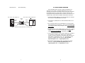
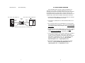
The Model 1205 has three pairs of jumpers (JP1, JP2 and JP3)
mounted on the internal PC board. See Figure 3, below. These
jumpers set clocking, carrier, and RTS/CTS delay independently for
ports A and B.
PORT B
PORT A
JP3
JP1
JP2
2
JP1
3
1
Port B
Port B
Port A
Port A
1
2
3
2
JP2
3
1
2
3
1
2
3
Port B
Port A
1
2
3
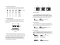
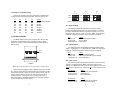
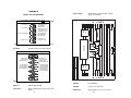
Figure 4. Detailed View of Model 1205 Jumpers Showing Factory Default Settings
JP1: RTS/CTS Delay
The setting for jumper JP1 determines the amount of delay
between the time the Model 1205 “sees” RTS and when it sends CTS.
In order to emulate either dial-up or leased line modems, you can set
this strap at either 0 msec, 7 msec or 53 msec. Note: Port A and Port
B must be configured separately. Jumper functions are identical.
JP1
Position 1&2
Position 2&3
Strap Removed
Setting
7 msec Delay (factory default)
53 msec Delay
0 msec Delay
JP2: Carrier Control
The setting for jumper JP2 determines whether the Model 1205’s
carrier is “constantly on” or “controlled by RTS”. Note: Port A and Port
B must be configured separately. Jumper functions are identical.
JP2
Position 1&2
Position 2&3
Strap Removed
Setting
Carrier “Controlled by RTS”
Carrier “Constantly ON” (factory default)
Not a Valid Setting
JP3: Clock Source
PORT B
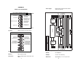
Figure 3. Model 1205 Jumper Orientation and Factory Default on Internal PC Board.
Figure 4 (following page) presents a detailed view of JP1, JP2 and
JP3, and also shows the factory default setting for each jumper. Please
observe that each pair contains one strap to configure Port A and one
strap to configure Port B. Observe also that each strap has three
possible positions: covering posts 1 & 2, covering posts 2 & 3, or
removed altogether. The detailed description for each pair of jumpers
presents all valid strap position options.
5
The setting for jumper JP3 determines whether clocking is internal,
external or received loopback. Note1: Only port A may be set for
external clock. Note2: If Port B is set for receive loopback clock, Port A
must be set for external clock. Port B may not be set for external clock.
JP3 (Port A)
Position 1 and 2
Position 2 and 3
Strap Removed
Setting
Internal Clock (factory default)
External Clock
Not a Valid Setting
JP3 (Port B)
Position 1 and 2
Position 2 and 3
Setting
Internal Clock (factory default)
Received Loopback Clock
6