1
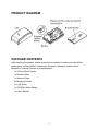
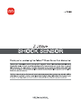
PRODUCT DIAGRAM
PACKAGE CONTENTS
After receiving the product, please inventory the contents to ensure you have all the
proper parts, as listed below. If anything is missing or damaged, please contact
Monoprice Customer Service for a replacement.
1x Z-Wave Shock Sensor
1x Bracket Holder
1x Adhesive Tape
2x Mounting Screws
1x Lock Screw
1x CR123A Lithium Battery
1x User's Manual
2
SPECIFICATIONS
Protocol: Z-Wave
Operating Frequency: 908.42 MHz
Operating Range: up to 100 feet line of sight
Operating Temperature: +5 ~ +140°F (-15 ~ +60°C)
Battery: 1x CR123A
INSTALLATION
Note: If you are installing a complete Z-Wave system for the first time, please refer to
the installation guide of your Z-Wave Interface Controller before installing this Shock
Sensor.
1. Press the locking tab on the top of the sensor cover and gently remove the cover.
2. Insert a battery into the battery holder, as shown in the diagram on the previous
page. Ensure that the polarity markings on the battery align with the polarity
markings on the battery holder.
3. Once the battery is installed, the LED will start flashing slowly. This indicates that
the sensor has not yet been "included" into a Z-Wave network.
4. Using the included adhesive tape or screws, mount the Bracket Holder in the
location you want to mount this sensor.
5. Slide the sensor over the bracket holder and fix it in place using the included lock
screw.
6. Proceed to the "Inclusion" section below.
3
INCLUSION
Now that the sensor is in its final location, it can be "included" into the network. Bring
your Z-Wave Interface Controller to the sensor's location. The distance between the
controller and the sensor should be less than 1 meter during the "inclusion" process.
1. If the cover is not already removed, press the locking tab on the top of the sensor
cover and gently remove it.
2. Following the instructions that came with your Z-Wave Controller, put the
controller into "include" mode.
3. When prompted, press and hold the Program/Tamper switch on the sensor for
about 1 second.
4. If the "inclusion" process is successful, the LED on the sensor will cease flashing
and glow steadily. If it does not, repeat steps 2-3.
5. Temporarily replace the cover.
6. Test the functionality of the sensor by creating a shock on the surface to which it
is attached. The sensor should send an Alarm Report (Type: 01, level 1) to the
Z-Wave Interface controller and the LED will flash once.
7. If you need to adjust the sensitivity, gently remove the cover again and proceed to
step 8. Otherwise, the installation and inclusion is complete and the cover can be
replaced for normal operation.
8. Adjust the sensitivity of the sensor using the sensitivity adjustment. Turn the
adjustment clockwise to increase sensitivity and counter-clockwise to decrease
sensitivity.
9. Repeat steps 5-7 until you are satisfied with the sensitivity setting.
EXCLUSION
If you wish to remove the sensor from your network, you will need to "exclude" it.
1. Press the locking tab on the top of the sensor cover and gently remove it.
2. Following the instructions that came with your Z-Wave Controller, put it into
"exclude" mode.
3. When prompted, press and hold the Program/Tamper switch on the sensor for
about 1 second to complete the "exclusion" process.
4. Replace the sensor cover.
ASSOCIATION
This sensor can be part of a single Association Group of up to 5 nodes. Following the
instructions that came with your Z-Wave Controller, associate it with another device.
4
SLEEP/AWAKE MODE
Under normal operation, the sensor is in "sleep" mode. While asleep, the sensor is still
detecting shocks, but is not in active communications with the network until it detects a
shock and sends an alarm signal.
When the cover is removed from the sensor, it is in "awake" mode, which allows it to
receive and reply to commands from the Z-Wave Controller.
OPERATION
When triggered, the sensor will send an ON status report (Basic Set, value: 0xFF) and
an Alarm Report (Type: 07, level 0xFF) to the controller and all associated Z-Wave
devices.
If the sensor has not been triggered for approximately 10 seconds, it will send an OFF
status report (Basic Set, value: 0x00) and an Alarm Report (Type: 07, level: 0x00) to
the controller and all associated Z-Wave devices.
EXTERNAL SWITCH
You can enhance the shock sensor by adding an external switch, such as a
door/window sensor. The sensor has two normally closed contact terminals, which can
be used for external switch wired contacts. When triggered, the external switch will send
an Alarm Report.
TAMPERING
When the cover is removed the tamper switch will trigger, causing the sensor to send an
Alarm Report to the controller and turning the LED on. Refer to your controller's device
log for alarm report details.
TECHNICAL SUPPORT
Monoprice is pleased to provide free, live, online technical support to assist you with
any questions you may have about installation, setup, troubleshooting, or product
recommendations. If you ever need assistance with your new product, please come
online to talk to one of our friendly and knowledgeable Tech Support Associates.
Technical support is available through the online chat button on our website
(www.monoprice.com) during regular business hours, 7 days a week. You can also
get assistance through email by sending a message to [email protected]
5
FCC STATEMENT
This equipment has been tested and found to comply with the limits for a Class B digital
device, pursuant to Part 15 of the FCC Rules. These limits are designed to provide
reasonable protection against harmful interference in a residential installation. This
equipment generates, uses and can radiate radio frequency energy and, if not installed
and used in accordance with the instruction, may cause harmful interference to radio
communications. However, there is no guarantee that interference will not occur in a
particular installation. If this equipment does cause harmful interference to radio or
television reception, which can be determined by turning the equipment off and on, the
user is encouraged to try and correct the interference by one of the following measures:
Reorient or relocate the receiving antenna.
Increase the separation between the equipment and receiver. Connect the equipment
into and outlet on a circuit different from that to which the receiver is connected.
Consult the dealer or an experienced radio/TV technician for help. This device complies
with Part 15 of the FCC Rules. Operation is subject to the following two conditions: (1)
this device may not cause harmful interference, and (2) this device must accept any
interference received, including interference that may cause undesired operation.
FCC Caution: Any changes or modifications not expressly approved by the party
responsible for compliance could void the user’s authority to operate this equipment.
6