1
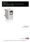
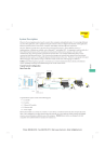
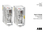
DriveIT Low Voltage AC Drives
User’s Manual
Pulse Encoder Interface Module
OTAC-01
Phone: 800.894.0412 - Fax: 888.723.4773 - Web: www.clrwtr.com - Email: [email protected]
2
Safety
WARNING! All electrical installation and maintenance work on the drive
should be carried out by qualified electricians only.
WARNING! The drive and adjoining equipment must be properly
grounded.
WARNING! Do not attempt any work on a powered drive. After
switching off the mains, always allow the intermediate circuit capacitors
5 minutes to discharge before working on the drive, the motor or the
motor cable. It is good practice to check (with a voltage indicating
instrument) that the drive is in fact discharged before beginning work.
WARNING! The motor cable terminals of the drive are at a dangerously
high voltage when mains power is applied, regardless of motor
operation.
WARNING! There can be dangerous voltages inside the drive from
external control circuits even when the drive mains power is shut off.
Exercise appropriate care when working on the unit. Neglecting these
instructions can cause physical injury or death.
Use of Warnings and Notes
There are two types of safety instructions throughout this manual:
•
Notes draw attention to a particular condition or fact, or give
information on a subject.
•
Warnings caution you about conditions which can result in serious
injury or death and/or damage to the equipment. They also tell you
how to avoid the danger. The warning symbols are used as follows:
Dangerous voltage warning warns of high voltage which can cause
physical injury and/or damage to the equipment.
Safety
Phone: 800.894.0412 - Fax: 888.723.4773 - Web: www.clrwtr.com - Email: [email protected]
3
Table of Contents
Safety . . . . . . . . . . . . . . . . . . . . . . . . . . . . . . . . . . . . . . . . . . . . . . . . . . . . . . . . . . . . 2
Use of Warnings and Notes . . . . . . . . . . . . . . . . . . . . . . . . . . . . . . . . . . . . . . . . . 2
Table of Contents . . . . . . . . . . . . . . . . . . . . . . . . . . . . . . . . . . . . . . . . . . . . . . . . . . 3
Installation . . . . . . . . . . . . . . . . . . . . . . . . . . . . . . . . . . . . . . . . . . . . . . . . . . . . . . . . 4
Preparing for Installation . . . . . . . . . . . . . . . . . . . . . . . . . . . . . . . . . . . . . . . . . . . 4
Installing the Module . . . . . . . . . . . . . . . . . . . . . . . . . . . . . . . . . . . . . . . . . . . . . . 5
Start-Up . . . . . . . . . . . . . . . . . . . . . . . . . . . . . . . . . . . . . . . . . . . . . . . . . . . . . . . . . 13
Configuration . . . . . . . . . . . . . . . . . . . . . . . . . . . . . . . . . . . . . . . . . . . . . . . . . . . 13
Diagnostics . . . . . . . . . . . . . . . . . . . . . . . . . . . . . . . . . . . . . . . . . . . . . . . . . . . . . . 16
Diagnostic LED . . . . . . . . . . . . . . . . . . . . . . . . . . . . . . . . . . . . . . . . . . . . . . . . . 16
Fault/Warning . . . . . . . . . . . . . . . . . . . . . . . . . . . . . . . . . . . . . . . . . . . . . . . . . . 16
Technical Data . . . . . . . . . . . . . . . . . . . . . . . . . . . . . . . . . . . . . . . . . . . . . . . . . . . . 18
Phone: 800.894.0412 - Fax: 888.723.4773 - Web: www.clrwtr.com - Email: [email protected]
4
Installation
Preparing for Installation
The OTAC-01 Module
The OTAC-01 Pulse Encoder Interface module is an interface for
connecting a digital pulse encoder to an ACS550 drive. A pulse
encoder should be used if accurate speed or position (angle) feedback
from the motor shaft is required.
Module Layout
Warning Sticker
Green LED
A
B
Z
Pass
Through
SCR
X0061
Compatibility
The OTAC-01 module is compatible with all ACS550 drives. To confirm
compatibility with a particular pulse encoder, compare the pulse
encoders requirements to the “Specifications” on page 19.
Installation
Phone: 800.894.0412 - Fax: 888.723.4773 - Web: www.clrwtr.com - Email: [email protected]
5
Installing the Module
Delivery Check
The OTAC-01 module package contains:
• OTAC-01 module
• Warning stickers in several languages
• This manual
Mounting
WARNING! Follow the safety instructions given in this guide and in the
ACS550 User’s Manual.
To mount the OTAC-01 module:
1. If not already off, remove mains power from the drive.
2. Remove the drive cover. (See instructions in the drive User’s Manual.)
3. Insert the OTAC-01 module’s
plastic hooks into the front of
the drive at SLOT 1.
4. Carefully fit the connector at
the other end of the module
into the drive connector.
5. Press until the retaining clip
locks the module into position.
7
5
4
NOTE! Signal and power
connections to the drive are
automatically made through a
6-pin connector.
6. Connect the ground lead to
the chassis screw terminal on the drive.
6
3
X0062
Installation
Phone: 800.894.0412 - Fax: 888.723.4773 - Web: www.clrwtr.com - Email: [email protected]
6
NOTE! Correct installation of the ground lead is essential for fulfilling
the EMC requirements and for proper operation of the module.
7. Non-English speaking locations: Add a warning sticker in the
appropriate language over the existing warning on the top of the
module.
Wiring – General
The pulse encoder should be connected to the OTAC-01 module with
cables as specified below.
Cable construction
4 × (2+1) Twisted pair cable with individual
and overall shields.
Conductor cross-sectional area 0.5 to 1.5 mm2
20 to 16 AWG
Terminal Designations
Use the following table for reference when wiring terminals.
Identification
OTAC
Encoder
Description
A
1
A
A
1
A
B
2
B
A+ • Max. signal frequency: 200 kHz
A- • Signal levels:
Logic “1”: 7.5 to 26 V
Logic “0”: < 0.8 V
B+
B
2
B
B-
Z
3
Z
Z
3
Z
Z+ • When the drive runs in the Forward direction,
channel A should lead channel B by 90° (electrical)
Z• Channel Z: One pulse per revolution (used in positioning
applications only)
(PWR) Vcc / PWR
(GND) 0 V / GND
SCR
• Input channels isolated from the logic, and ground
OTAC-01 does not provide a power supply. These
terminals are used for daisy chaining between the power
supply and the encoder.
SCR / Shield Used for grounding of the encoder cable shields.
Connected internally to the drive frame.
Installation
Phone: 800.894.0412 - Fax: 888.723.4773 - Web: www.clrwtr.com - Email: [email protected]
7
Wiring – The Encoder Power
The OTAC-01 module does not supply power for the encoder. An
external power supply (as diagrammed below) is recommended. The
drive’s 24 VDC supply from terminals X1:10 and X1:11 can be used if
the total draw on the supply does not exceed 250 mA. Use the following
table to determine if the drive’s supply can be used.
Loads Using the Drive’s 24 VDC Supply
Number of digital inputs used (DI1…DI6)
mA
x 15 mA each =
Encoder current requirement =
Total requirements for any other user connection(s) to drive’s 24 VDC =
Total (must be less than 250 mA) =
1. Connect as follows:
Encoder
0V
Vcc
OTAC-01
Module
External
Power Supply
(PWR)
Vcc
(GND)
0V
SCR
Wiring – The Encoder
1. Determine the encoder wiring configuration:
• Refer to “Phasing” on page 8 to determine if the encoder has normal
pulse order – encoder channel A/1 pulse leads channel B/2 pulse.
• Refer to “Encoder Output Types” on page 9 to determine the
encoder’s output type.
• For push-pull types, refer to the manufacturer’s recommendation for
connection – either single-ended or differential can be used.
2. Refer to “Wiring Diagrams” on page 10, select the appropriate diagram,
and wire the encoder.
Installation
Phone: 800.894.0412 - Fax: 888.723.4773 - Web: www.clrwtr.com - Email: [email protected]
8
Note: Normally, ground the cable shield only at the drive end. However,
if the encoder is isolated from the motor, and from ground, then connect
the cable shields to both the OTAC module and the encoder housing.
Note: Do not route the encoder cables parallel to power (e.g. motor)
cables.
3. Verify correct encoder phasing. See options below.
Phasing
When the encoder is connected correctly, running the drive in the
Forward (positive speed reference) direction should produce a positive
encoder speed feedback.
Option A: Oscilloscope Test. On incremental encoders, the two
output channels, usually marked A and B or 1 and 2, are 90° (electrical)
apart from each other. When rotated clockwise, most encoders – but
not all – have channel A/1 leading channel B/2 as illustrated below.
Determine the leading channel by referring to the encoder
documentation or by measuring with an oscilloscope.
90°
A or 1
A or 1
Diagrams show normal phasing:
Pulse A/1 leads (i.e. rises earlier than)
pulse B/2.
B or 2
B or 2
Z or 0
Z or 0
Connect the zero reference output
channel (usually marked 0, N or Z)
only if parameter 5010 Z PLS ENABLE =
1 (ENABLE).
The encoder output channel that leads when the drive runs Forward
should be connected to OTAC terminal A. The output channel that trails
should be connected to OTAC terminal B.
Option B: Functional Test. For this test:
• Temporarily, switch the drive to scalar mode (parameter 9904 = 3), if
not already there.
Installation
Phone: 800.894.0412 - Fax: 888.723.4773 - Web: www.clrwtr.com - Email: [email protected]
9
• Run the drive in the forward direction.
• Verify that parameter 0147 MECH REVS is increasing in the positive
direction.
• If not, switch the A/A (or 1/1) connections.
Encoder Output Types
The following diagrams identify the typical encoder output types.
Push-pull
Open collector (Sinking) Open emitter (Sourcing)
VCC
VCC
VCC
OUT
OUT
OUT
VCC = Encoder input power supply voltage
Installation
Phone: 800.894.0412 - Fax: 888.723.4773 - Web: www.clrwtr.com - Email: [email protected]
10
Wiring Diagrams
Push-Pull Type Encoder Output
Diagram assumes normal pulse order in Forward rotation: Pulse A/1 leads as
diagrammed below
A/1
B/2
For encoders with pulse 2 leading, change diagram for these connections:
• Encoder A/1 and B/2 should be wired to OTAC terminals B and A respectively.
• Encoder A/1 and B/2 (if present) should be wired to OTAC terminals B and A
respectively.
Differential connection
OTAC-01
Module
Encoder
SCR 0V VCC
1
A
1
A
2
B
2
0
0
B
Z
Z
(PWR)
(GND)
Note 1
Encoder
Power
Supply
SCR
Single-ended connection
OTAC-01
Module
Encoder
1
A
A
2
B
B
0
SCR 0V
VCC
Z
Z
(PWR)
(GND)
Encoder
Power
Supply
Note 1
SCR
Note 1: Connect the cable shield at the encoder housing, if, and only if, the
encoder is isolated from the motor, and from ground.
Installation
Phone: 800.894.0412 - Fax: 888.723.4773 - Web: www.clrwtr.com - Email: [email protected]
11
Open Collector (Sinking) Encoder Output
Diagram assumes normal pulse order in Forward rotation: Pulse 1 leads as
diagrammed below
A/1
B/2
For encoders with pulse B/2 leading, change diagram for these connections:
Encoder A/1 and B/2 should be wired to OTAC terminals B and A respectively.
OTAC-01
Module
Encoder
A
1
A
B
2
B
Z
0
Z
SCR 0V VCC
(PWR)
(GND)
Note 1
Encoder
Power
Supply
SCR
Note 1: Connect the cable shield at the encoder housing, if, and only if, the
encoder is isolated from the motor, and from ground.
Installation
Phone: 800.894.0412 - Fax: 888.723.4773 - Web: www.clrwtr.com - Email: [email protected]
12
Open Emitter (Sourcing) Encoder Output
Diagram assumes normal pulse order in Forward rotation: Pulse 1 leads as
diagramed below
A/1
B/2
For encoders with pulse B/2 leading, change diagram for these connections:
Encoder A/1 and B/2 should be wired to OTAC terminals B and A respectively.
OTAC-01
Module
Encoder
1
A
A
2
B
B
0
SCR 0V
VCC
Z
Z
(PWR)
(GND)
Note 1
Encoder
Power
Supply
SCR
Note 1: Connect the cable shield at the encoder housing, if, and only if, the
encoder is isolated from the motor, and from ground.
Replace Drive Cover
1. Refer to the drive’s User’s manual and replace the drive’s cover.
Apply Power
1. Turn on the mains power to the drive.
Note! When power is applied to the drive, the LED on the OTAC
module should light.
2. Continue with the next section, Start-Up.
Installation
Phone: 800.894.0412 - Fax: 888.723.4773 - Web: www.clrwtr.com - Email: [email protected]
13
Start-Up
Configuration
To configure the operation of the OTAC-01 module:
1. Power up the drive.
2. Use the control panel on the drive and set the parameters described
below.
Operating Data
The following parameters provide feedback from the encoder. The drive
sets the parameter values based on measurements or calculations. You
cannot set these values directly, but you can use Group 50 parameters
to control mechanical angle and revolution data.
Code Description
0146 MECH ANGLE
Group 01: Operating Data
Range
Resolution
0…32767
1 (≅ 0.01°)
Default
0
Defines the motor shaft’s angular position to about 0.01° (32,768 divisions for 360°). The
position is defined as 0 at power up.
During operation the zero position can be set by:
• A Z-pulse input, if parameter 5010 Z PLS ENABLE = 1 (ENABLE)
• Parameter 5011 POSITION RESET, if parameter 5010 Z PLS ENABLE = 2 (DISABLE)
• Any status change of parameter 5002 ENCODER ENABLE
0147 MECH REVS
-32767…32767
1
0
A signed integer that counts full revolutions of the motor shaft. The value:
• Increments when parameter 0146 MECH ANGLE changes from 32767 to 0
• Decrements when parameter 0146 MECH ANGLE changes from 0 to 32767
0148 Z PLS DETECTED
0, 1
1
0
When a Z-pulse defines the zero position, the shaft must pass through the zero position to
trigger a Z-pulse. Until then, the shaft position is unknown (the drive uses the shaft position at
power up as zero). This parameter signals when parameter 0146 MECH ANGLE is valid. This
parameter starts at zero on power-up and changes to 1 only if:
• Parameter 5010 Z PLS ENABLE = ENABLE and
• An encoder Z-pulse has been detected.
Start-Up
Phone: 800.894.0412 - Fax: 888.723.4773 - Web: www.clrwtr.com - Email: [email protected]
14
Encoder
This group defines the setup for encoder use:
• Set the number of encoder pulses per shaft revolution.
• Enable the encoder operation.
• Defines how mechanical angle and revolution data is reset.
Note! a check under the heading “S” indicates that the parameter can
only be modified when the drive is stopped.
Code Description
5001 PULSE NR
Group 50: Encoder
Range
Resolution
0…16384 ppr
1
Default
1024
S
9
Sets the number of pulses provided by an optional encoder for each full motor shaft revolution.
5002 ENCODER ENABLE
0, 1
1
0
9
Enables/disables optional external encoder.
0 = DISABLE – Drive uses speed feedback derived from the internal motor model (applies for
any setting of parameter 9904 MOTOR CTRL MODE).
1 = ENABLE – Drive uses feedback from an optional encoder. This function requires the Pulse
Encoder Interface Module (OTAC-01) and an encoder. Operation depends on the setting of
parameter 9904 MOTOR CTRL MODE:
• 9904 = 1 (VECTOR: SPEED), the encoder provides improved speed feedback and improved
low speed torque accuracy.
• 9904 = 2 (VECTOR: TORQ), the encoder provides improved speed feedback and improved
low speed torque accuracy.
• 9904 = 3 (SCALAR: SPEED), the encoder provides speed feedback. (This is not closed loop
speed regulation. However, using parameter 2608 SLIP COMP RATIO and an encoder
improves steady state speed accuracy.)
5003 ENCODER FAULT
1, 2
1
1
9
Defines the drive response if the encoder signal is lost.
1 = FAULT – A fault is generated, and the motor coasts to a stop.
2 = WARNING – An alarm is generated and the ACS550 operates as is if parameter 5002
ENCODER ENABLE = 0 (DISABLE), that is, speed feedback is derived from the internal motor
model.
5010 Z PLS ENABLE
0, 1
1
0
9
Enables/disables the use of an encoder’s Z-pulse to define the motor shaft’s zero position.
When enabled, a Z-pulse input resets parameter 0146 MECH ANGLE to zero to define the shaft’s
zero position. This function requires an encoder that provides Z-pulse signals.
0 = DISABLE – Z-pulse input is not present or ignored if present.
1 = ENABLE – A Z-pulse input resets parameter 0146 MECH ANGLE to zero.
Start-Up
Phone: 800.894.0412 - Fax: 888.723.4773 - Web: www.clrwtr.com - Email: [email protected]
15
Code Description
5011 POSITION RESET
Group 50: Encoder
Range
Resolution
0, 1
1
Default
0
S
Resets the encoder’s position feedback. This parameter is self-clearing.
0 = DISABLE – Inactive.
1 = ENABLE – Resets the encoder position feedback. Parameters reset depends on the state of
parameter 5010 Z PLS ENABLE:
• 5010 = ENABLE – Reset applies only to parameter 0147 MECH REVS.
• 5010 = DISABLE – Reset applies to parameters 0147 MECH REVS and 0146 MECH ANGLE.
Start-Up
Phone: 800.894.0412 - Fax: 888.723.4773 - Web: www.clrwtr.com - Email: [email protected]
16
Diagnostics
Diagnostic LED
There is one diagnostic LED on the OTAC-01 module. If the OTAC-01
is properly installed, the green LED lights when the drive is powered up.
If the LED does not light after power-up:
Step down this column.
If an item is TRUE, look to
the RIGHT for suggestions.
The configuration may have
failed.
The module connection may
be damaged
Corrective Action
Cycle the power supply of the drive.
Warning! Dangerous voltages are present
on the connector. Power down before
attempting to repair connector pins.
• Power down.
• Remove the module and check the condition of
the pins in the 6-pin connector.
• Reconnect and retest.
The module may have failed. Replace the module.
Fault/Warning
If the ACS550 detects that the encoder signal is lost, the drive
operation and the diagnostic message are both controlled by parameter
5003 ENCODER FAULT:
• 5003 = 1 (FAULT) – The drive generates a fault (23 ENCODER ERR),
and the motor coasts to a stop.
• 5003 = 2 (WARNING) – The drive generates an alarm (2024 ENCODER
ERROR) and operates as is if parameter 5002 ENCODER ENABLE = 0
(DISABLE), that is, speed feedback is derived from the internal motor
model.
Diagnostics
Phone: 800.894.0412 - Fax: 888.723.4773 - Web: www.clrwtr.com - Email: [email protected]
17
In case of a fault or alarm signal, check for and correct:
Code
23
Name In
Panel
ENCODER
ERR
Description and Recommended Corrective Action
The drive is not detecting a valid encoder signal. Check for
and correct:
• Encoder presence and proper connection (reverse wired,
loose connection, or short circuit).
• Voltage logic levels are outside of the specified range.
2024
• Pulse Encoder Interface Module, OTAC-01, presence and
proper connection to the ACS550.
ENCODER
ERROR
• Wrong value entered in parameter 5001 PULSE NR. A
wrong value will only be detected if the error is such that
the calculated slip is greater than 4 times the rated slip of
the motor.
• Encoder is not being used, but parameter 5002 ENCODER
ENABLE = 1 (ENABLED)
Note: The validity of the encoder signal is also checked during the
ID-run. See parameter 9910 MOTOR ID RUN. If the drive detects an
encoder problem during the ID-run, the drive provides an alarm.
Parameter 5003 FAULT ENABLE controls the drive’s fault/alarm response
to encoder errors only after the ID-run is completed.
Diagnostics
Phone: 800.894.0412 - Fax: 888.723.4773 - Web: www.clrwtr.com - Email: [email protected]
18
Technical Data
Dimensions
Module dimensions are:
Ref.
mm
in
H
14.5
0.57
L
77.8
3.06
W
58.8
2.31
X0063
Enclosure Degree of Protection
The module is mounted inside the drive enclosure. Refer to the drive’s
rating.
Ambient Conditions
The module is mounted inside the drive enclosure. Refer to the drive’s
requirements.
Connectors
Connectors on the module:
• 6-pin connector
• Three, 3-pin, screw-type, non-detachable terminal blocks that accept
wire connectors up to 1.5 mm2 (16 AWG).
• Ground lead
Technical Data
Phone: 800.894.0412 - Fax: 888.723.4773 - Web: www.clrwtr.com - Email: [email protected]
19
Specifications
Module Specifications
The OTAC-01 module:
• Supports three channels: CH A, CH B, CH Z.
• Includes pass-through terminals to connect an external power supply
(required) to the pulse encoder.
• All materials are UL-approved.
Channel Specifications
Channel specifications:
• Differential or single-ended
• Maximum input frequency: 200 kHz
• Input voltage range: 7.5 to 26 V (measured at the OTAC module)
• Nominal input impedance: 660 ohm (at 24 VDC)
• Isolated from logic and ground
Technical Data
Phone: 800.894.0412 - Fax: 888.723.4773 - Web: www.clrwtr.com - Email: [email protected]