1
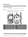
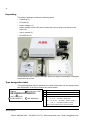
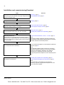
ABB Drives
User’s Manual
FlashDrop
MFDT-01
Phone: 800.894.0412 - Fax: 888.723.4773 - Web: www.clrwtr.com - Email: [email protected]
FlashDrop
MFDT-01
User’s Manual
3AFE68591074 Rev B
EN
EFFECTIVE: 5.3.2007
© 2007 ABB Oy. All Rights Reserved.
Phone: 800.894.0412 - Fax: 888.723.4773 - Web: www.clrwtr.com - Email: [email protected]
5
Table of contents
About the manual . . . . . . . . . . . . . . . . . . . . . . . . . . . . . . . . . . . . . . . . . . . . . . . . . . . . . . . . . . . . . . 9
What this chapter contains . . . . . . . . . . . . . . . . . . . . . . . . . . . . . . . . . . . . . . . . . . . . . . . . . . . . . . . .
Intended audience . . . . . . . . . . . . . . . . . . . . . . . . . . . . . . . . . . . . . . . . . . . . . . . . . . . . . . . . . . . . . . .
Additional information for users . . . . . . . . . . . . . . . . . . . . . . . . . . . . . . . . . . . . . . . . . . . . . . . . . . . . .
Product training . . . . . . . . . . . . . . . . . . . . . . . . . . . . . . . . . . . . . . . . . . . . . . . . . . . . . . . . . . . . . . . . .
Product and service inquiries . . . . . . . . . . . . . . . . . . . . . . . . . . . . . . . . . . . . . . . . . . . . . . . . . . . . . .
Providing feedback on ABB Drives manuals . . . . . . . . . . . . . . . . . . . . . . . . . . . . . . . . . . . . . . . . . . .
9
9
9
9
9
9
Getting started . . . . . . . . . . . . . . . . . . . . . . . . . . . . . . . . . . . . . . . . . . . . . . . . . . . . . . . . . . . . . . . . 11
What this chapter contains . . . . . . . . . . . . . . . . . . . . . . . . . . . . . . . . . . . . . . . . . . . . . . . . . . . . . . .
Overview . . . . . . . . . . . . . . . . . . . . . . . . . . . . . . . . . . . . . . . . . . . . . . . . . . . . . . . . . . . . . . . . . . . . .
Unpacking . . . . . . . . . . . . . . . . . . . . . . . . . . . . . . . . . . . . . . . . . . . . . . . . . . . . . . . . . . . . . . . . . . . .
Type designation label . . . . . . . . . . . . . . . . . . . . . . . . . . . . . . . . . . . . . . . . . . . . . . . . . . . . . . . . . .
Compatibility . . . . . . . . . . . . . . . . . . . . . . . . . . . . . . . . . . . . . . . . . . . . . . . . . . . . . . . . . . . . . . . . . .
Safety instructions . . . . . . . . . . . . . . . . . . . . . . . . . . . . . . . . . . . . . . . . . . . . . . . . . . . . . . . . . . . . . .
Installation and commissioning flowchart . . . . . . . . . . . . . . . . . . . . . . . . . . . . . . . . . . . . . . . . . . . .
Providing the programming tip with a safety line . . . . . . . . . . . . . . . . . . . . . . . . . . . . . . . . . . . . . . .
Charging . . . . . . . . . . . . . . . . . . . . . . . . . . . . . . . . . . . . . . . . . . . . . . . . . . . . . . . . . . . . . . . . . . . . .
Connecting . . . . . . . . . . . . . . . . . . . . . . . . . . . . . . . . . . . . . . . . . . . . . . . . . . . . . . . . . . . . . . . . . . .
Mains electricity supply (AC power source) – charger – base unit . . . . . . . . . . . . . . . . . . . . . . .
FlashDrop Control Panel – base unit . . . . . . . . . . . . . . . . . . . . . . . . . . . . . . . . . . . . . . . . . . . . .
PC – base unit . . . . . . . . . . . . . . . . . . . . . . . . . . . . . . . . . . . . . . . . . . . . . . . . . . . . . . . . . . . . . .
FlashDrop – drive . . . . . . . . . . . . . . . . . . . . . . . . . . . . . . . . . . . . . . . . . . . . . . . . . . . . . . . . . . . .
How to install DrivePM tool, version 1.1 or later . . . . . . . . . . . . . . . . . . . . . . . . . . . . . . . . . . . . . . .
How to download parameter templates to the FlashDrop . . . . . . . . . . . . . . . . . . . . . . . . . . . . . . . .
Storing . . . . . . . . . . . . . . . . . . . . . . . . . . . . . . . . . . . . . . . . . . . . . . . . . . . . . . . . . . . . . . . . . . . . . . .
11
11
12
12
13
13
14
15
15
15
15
15
15
16
16
17
17
Operation . . . . . . . . . . . . . . . . . . . . . . . . . . . . . . . . . . . . . . . . . . . . . . . . . . . . . . . . . . . . . . . . . . . . 19
What this chapter contains . . . . . . . . . . . . . . . . . . . . . . . . . . . . . . . . . . . . . . . . . . . . . . . . . . . . . . .
Using the FlashDrop for parametrization of drives . . . . . . . . . . . . . . . . . . . . . . . . . . . . . . . . . . . . .
FlashDrop parametrization flowchart . . . . . . . . . . . . . . . . . . . . . . . . . . . . . . . . . . . . . . . . . . . . .
FlashDrop Control Panel and its operation . . . . . . . . . . . . . . . . . . . . . . . . . . . . . . . . . . . . . . . . . . .
Control panel overview . . . . . . . . . . . . . . . . . . . . . . . . . . . . . . . . . . . . . . . . . . . . . . . . . . . . . . . .
Status line . . . . . . . . . . . . . . . . . . . . . . . . . . . . . . . . . . . . . . . . . . . . . . . . . . . . . . . . . . . . . . .
Operation principles . . . . . . . . . . . . . . . . . . . . . . . . . . . . . . . . . . . . . . . . . . . . . . . . . . . . . . . . . .
How to do common tasks . . . . . . . . . . . . . . . . . . . . . . . . . . . . . . . . . . . . . . . . . . . . . . . . . . . .
Checking the properties and compatibility . . . . . . . . . . . . . . . . . . . . . . . . . . . . . . . . . . . . . . . . .
Time & Date mode . . . . . . . . . . . . . . . . . . . . . . . . . . . . . . . . . . . . . . . . . . . . . . . . . . . . . . . . . . .
How to set the date and time . . . . . . . . . . . . . . . . . . . . . . . . . . . . . . . . . . . . . . . . . . . . . . . . .
How to adjust the display contrast . . . . . . . . . . . . . . . . . . . . . . . . . . . . . . . . . . . . . . . . . . . . .
How to view information about the drive connected to the FlashDrop . . . . . . . . . . . . . . . . . .
Phone: 800.894.0412 - Fax: 888.723.4773 - Web: www.clrwtr.com - Email: [email protected]
19
19
21
22
22
23
23
24
24
25
25
26
27
6
How to download templates from the Internet . . . . . . . . . . . . . . . . . . . . . . . . . . . . . . . . . . . .
Parameters mode . . . . . . . . . . . . . . . . . . . . . . . . . . . . . . . . . . . . . . . . . . . . . . . . . . . . . . . . . . .
How to initialize (create) a parameter set . . . . . . . . . . . . . . . . . . . . . . . . . . . . . . . . . . . . . . .
How to upload a parameter set from the drive . . . . . . . . . . . . . . . . . . . . . . . . . . . . . . . . . . .
How to view the parameter set information . . . . . . . . . . . . . . . . . . . . . . . . . . . . . . . . . . . . . .
How to edit a parameter set . . . . . . . . . . . . . . . . . . . . . . . . . . . . . . . . . . . . . . . . . . . . . . . . .
How to edit the value of a parameter in a set . . . . . . . . . . . . . . . . . . . . . . . . . . . . . . . . . . . .
How to view and edit the values of changed parameters in a set . . . . . . . . . . . . . . . . . . . . .
How to edit the visibility of a parameter in a set . . . . . . . . . . . . . . . . . . . . . . . . . . . . . . . . . .
How to edit the visibility of a parameter group in a set . . . . . . . . . . . . . . . . . . . . . . . . . . . . .
How to delete a parameter set . . . . . . . . . . . . . . . . . . . . . . . . . . . . . . . . . . . . . . . . . . . . . . .
How to download a parameter set to a drive . . . . . . . . . . . . . . . . . . . . . . . . . . . . . . . . . . . . .
How to view information about the FlashDrop . . . . . . . . . . . . . . . . . . . . . . . . . . . . . . . . . . .
How to find out the control panel version . . . . . . . . . . . . . . . . . . . . . . . . . . . . . . . . . . . . . . .
28
29
30
32
34
35
36
38
40
41
42
43
44
44
Fault tracing . . . . . . . . . . . . . . . . . . . . . . . . . . . . . . . . . . . . . . . . . . . . . . . . . . . . . . . . . . . . . . . . . 45
What this chapter contains . . . . . . . . . . . . . . . . . . . . . . . . . . . . . . . . . . . . . . . . . . . . . . . . . . . . . . . 45
Error messages . . . . . . . . . . . . . . . . . . . . . . . . . . . . . . . . . . . . . . . . . . . . . . . . . . . . . . . . . . . . . . . 45
Maintenance and hardware diagnostics . . . . . . . . . . . . . . . . . . . . . . . . . . . . . . . . . . . . . . . . . . 47
What this chapter contains . . . . . . . . . . . . . . . . . . . . . . . . . . . . . . . . . . . . . . . . . . . . . . . . . . . . . . .
Safety . . . . . . . . . . . . . . . . . . . . . . . . . . . . . . . . . . . . . . . . . . . . . . . . . . . . . . . . . . . . . . . . . . . . . . .
Maintenance intervals . . . . . . . . . . . . . . . . . . . . . . . . . . . . . . . . . . . . . . . . . . . . . . . . . . . . . . . . . .
Software . . . . . . . . . . . . . . . . . . . . . . . . . . . . . . . . . . . . . . . . . . . . . . . . . . . . . . . . . . . . . . . . . . . . .
Base unit . . . . . . . . . . . . . . . . . . . . . . . . . . . . . . . . . . . . . . . . . . . . . . . . . . . . . . . . . . . . . . . . . . . .
Battery replacement . . . . . . . . . . . . . . . . . . . . . . . . . . . . . . . . . . . . . . . . . . . . . . . . . . . . . . . . . .
Control panel . . . . . . . . . . . . . . . . . . . . . . . . . . . . . . . . . . . . . . . . . . . . . . . . . . . . . . . . . . . . . . . . .
Cleaning . . . . . . . . . . . . . . . . . . . . . . . . . . . . . . . . . . . . . . . . . . . . . . . . . . . . . . . . . . . . . . . . . . .
Battery . . . . . . . . . . . . . . . . . . . . . . . . . . . . . . . . . . . . . . . . . . . . . . . . . . . . . . . . . . . . . . . . . . . .
LEDs . . . . . . . . . . . . . . . . . . . . . . . . . . . . . . . . . . . . . . . . . . . . . . . . . . . . . . . . . . . . . . . . . . . . . . . .
47
47
47
47
48
48
48
48
48
49
Technical data . . . . . . . . . . . . . . . . . . . . . . . . . . . . . . . . . . . . . . . . . . . . . . . . . . . . . . . . . . . . . . . 51
What this chapter contains . . . . . . . . . . . . . . . . . . . . . . . . . . . . . . . . . . . . . . . . . . . . . . . . . . . . . . .
Weight . . . . . . . . . . . . . . . . . . . . . . . . . . . . . . . . . . . . . . . . . . . . . . . . . . . . . . . . . . . . . . . . . . . . . .
Time of use with one charge . . . . . . . . . . . . . . . . . . . . . . . . . . . . . . . . . . . . . . . . . . . . . . . . . . . . .
Charge time . . . . . . . . . . . . . . . . . . . . . . . . . . . . . . . . . . . . . . . . . . . . . . . . . . . . . . . . . . . . . . . . . .
Ambient conditions . . . . . . . . . . . . . . . . . . . . . . . . . . . . . . . . . . . . . . . . . . . . . . . . . . . . . . . . . . . . .
Materials . . . . . . . . . . . . . . . . . . . . . . . . . . . . . . . . . . . . . . . . . . . . . . . . . . . . . . . . . . . . . . . . . . . . .
Applicable standards . . . . . . . . . . . . . . . . . . . . . . . . . . . . . . . . . . . . . . . . . . . . . . . . . . . . . . . . . . .
CE marking . . . . . . . . . . . . . . . . . . . . . . . . . . . . . . . . . . . . . . . . . . . . . . . . . . . . . . . . . . . . . . . . . . .
Dimensions . . . . . . . . . . . . . . . . . . . . . . . . . . . . . . . . . . . . . . . . . . . . . . . . . . . . . . . . . . . . . . . . . . .
51
51
51
51
51
51
51
51
52
Phone: 800.894.0412 - Fax: 888.723.4773 - Web: www.clrwtr.com - Email: [email protected]
7
Glossary . . . . . . . . . . . . . . . . . . . . . . . . . . . . . . . . . . . . . . . . . . . . . . . . . . . . . . . . . . . . . . . . . . . . . 53
Additional information . . . . . . . . . . . . . . . . . . . . . . . . . . . . . . . . . . . . . . . . . . . . . . . . . . . . . . . . . 55
State diagram of the panel user interface . . . . . . . . . . . . . . . . . . . . . . . . . . . . . . . . . . . . . . . . . . . . 55
Drive ratings table . . . . . . . . . . . . . . . . . . . . . . . . . . . . . . . . . . . . . . . . . . . . . . . . . . . . . . . . . . . . . . 57
Phone: 800.894.0412 - Fax: 888.723.4773 - Web: www.clrwtr.com - Email: [email protected]
9
About the manual
What this chapter contains
This chapter contains information about intended audience of this manual and where
the user can get additional information, product and service inquiries, product
training and provide feedback on this manual.
Intended audience
The manual is intended for persons using the FlashDrop. Read it before use.
The manual is written for readers worldwide. Both SI and imperial units are shown.
Additional information for users
Please visit at FlashDrop product page for more information about FlashDrop.
• Go to the site ABB website with your Internet browser
• Select Our offerings: ABB Product Guide
• -> Motors, Drives and Power Electronics: Drives
• -> Low Voltage AC Drives: either Component drives or General Machinery drives
or Standard drives
• Select FlashDrop under the Links title
There you will also find links to FlashDrop product training.
Product training
For information on ABB product training, navigate to ABB website and select
Drives – Training courses on the right pane.
Product and service inquiries
Address any inquiries about the product to your local ABB representative, quoting
the type code and serial number of the unit in question. A listing of ABB sales,
support and service contacts can be found by navigating to ABB website and
selecting Drives – World wide service contacts on the right pane.
Providing feedback on ABB Drives manuals
Your comments on our manuals are welcome. Go to ABB website, then
select successively Drives – Document Library – Manuals feedback form on the right
pane.
About the manual
Phone: 800.894.0412 - Fax: 888.723.4773 - Web: www.clrwtr.com - Email: [email protected]
11
Getting started
What this chapter contains
The chapter describes the construction and installation of the FlashDrop.
Overview
The FlashDrop is a device used to edit parameter values and visibility and for
copying parameters fast to unpowered drives.
8
8
10
1
9
1
11
7
2
12
6
13
3
5
3
14
4
1 Base unit
8 Programming tip cable
2 FlashDrop Control Panel
9 Clip for the programming tip cable
3 Programming tip
10 Battery charger connection
4 Programming tip cap
11 Battery charge level indicators (four LEDs)
5 Programming tip safety line (not provided)
12 Power switch
6 Programming tip clip
13 FlashDrop Control Panel and PC connection
7 Programming tip holder
14 Power OK and Fault LEDs (see LEDs on page 49)
Getting started
Phone: 800.894.0412 - Fax: 888.723.4773 - Web: www.clrwtr.com - Email: [email protected]
12
Unpacking
The delivery package contains the following items:
• FlashDrop (1)
• PC cable (2)
• battery charger (3)
• battery charger mains (AC power) cable with a set of plugs (not shown in the
figure) (4)
• user´s manual (5)
• DrivePM CD (6).
3
2
4
6
1
5
Check that there are no signs of damage. Notify the shipper immediately if damaged
components are found.
Type designation label
The type designation label is attached to the back of the base unit. An example label
and explanation of the label contents are shown below.
2
ABB Oy
SW version: 1.04E
lllllllllllllllllllllllllllllllllllllllllllllll
3
TYPE: MFDT-01
2 Firmware version
3 ABB MRP code
4 Serial number of format YWWRXXXX, where
MRP code: 68566380
1
1 Type code
4
S/N: 648C0001
Type designation label
Y:
5…9, A, … for 2005…2009, 2010, …
WW:
01, 02, 03, … for week 1, week 2, week 3, …
R:
A, B, C … for product revision number
XXXX: Integer starting every week from 0001
Getting started
Phone: 800.894.0412 - Fax: 888.723.4773 - Web: www.clrwtr.com - Email: [email protected]
13
Compatibility
The FlashDrop base unit is compatible with:
• ACS150, drive firmware version 1.31b or later
• ACS350, drive firmware version 2.41a or later
• ACS550-01 and ACH550-01, drive firmware version 3.10b or later. There
needs to be a FlashDrop connector in the drive under the control panel.
• DrivePM version 1.1 or later
FlashDrop is non-compatible with older drive firmware versions. The use with older
firmware is not allowed.
To find out the firmware version of your drive, see page 27, or check the value of
parameter 3301 FW VERSION in the drive.
To find out the firmware and hardware versions of your FlashDrop, see page 44.
To create and edit FlashDrop parameter sets with the DrivePM PC tool or FlashDrop,
correct templates are needed. Both DrivePM and FlashDrop templates can be
downloaded from the ABB Internet site.
Safety instructions
Follow these safety instructions when using the FlashDrop.
WARNING! Ignoring the following instructions can cause physical injury or death, or
damage to the equipment.
• Use the FlashDrop only with an unpowered drive.
• Do not use the FlashDrop if the cable is broken.
Getting started
Phone: 800.894.0412 - Fax: 888.723.4773 - Web: www.clrwtr.com - Email: [email protected]
14
Installation and commissioning flowchart
Task
Unpack and check the units.
See/note
Unpacking, page 12
Check the type code indicated on the type designation label Type designation label, page 12
against the original order.
Charge the FlashDrop base unit.
Charging, page 15
Specify clock settings for the FlashDrop.
How to set the date and time, page 25
Adjust the display contrast, if necessary.
How to adjust the display contrast, page 26
Check the compatibility.
Safety instructions, page 13
Check parameter table version and other properties.
Checking the properties and compatibility, page 24
Install the DrivePM tool.
How to install DrivePM tool, version 1.1 or later, page 16
Confirm that your computer meets the minimum system
requirements to install DrivePM tool. See DrivePM CD-ROM
cover for requirements or readme.txt file in the root directory
of the CD-ROM.
Note:
Download the FlashDrop base unit parameter templates
from the DrivePM to the FlashDrop.
How to download templates from the DrivePM to FlashDrop
base unit, page 28.
Parameter templates supplied by DrivePM CD-ROM are
also installed in dedicated DrivePM subfolders for ACS150,
ACS350, ACS550 and ACH550 products.
Note:
The delivered FlashDrop base unit does not include any
parameter templates as default. The necessary templates
need to be downloaded to FlashDrop. The editing of
parameter set in FlashDrop base unit requires that
appropriate parameter template is saved in FlashDrop base
unit.
If necessary, download templates from the Internet and
download to the FlashDrop.
Checking the properties and compatibility, page 24
How to download templates from the Internet, page 28.
Note:
The downloading of templates from the Internet is
necessary only when an appropriate template cannot be
found in DrivePM subfolder.
Getting started
Phone: 800.894.0412 - Fax: 888.723.4773 - Web: www.clrwtr.com - Email: [email protected]
15
Providing the programming tip with a safety line
To avoid losing the cap of the programming tip, you can attach a thin line (not
provided) to the eyelets of the programming tip.
Charging
Charge the FlashDrop.
Note: The light refers to the LED on the charger. The LEDs on the FlashDrop base
unit are always all lit when the charger is connected and FlashDrop base unit is
switched on.
When charging the FlashDrop battery, the charger operation is the following:
1. Initialization (orange light)
2. Charging (red light)
3. Finalizing the charge (blinking green light)
4. Battery is charged (green light).
Note: To charge the battery again, the charger must be removed from the FlashDrop
so that the initialization (orange light) is activated in the charger. This is a safety
procedure. If the FlashDrop is switched on and charged once, it can not be charged
again before it is removed from the charger. You can use the FlashDrop while
charging. Please see the charger user’s manual for more information.
Connecting
Mains electricity supply (AC power source) – charger – base unit
Charge the base unit with the provided charger only.
FlashDrop Control Panel – base unit
The control panel is connected to the base unit with the provided RJ-45 connector.
PC – base unit
To load parameter sets between the DrivePM PC tool and the FlashDrop, connect
your PC to the base unit with the PC cable. Use the provided cable only. The
FlashDrop panel has to be removed for PC connection.
Getting started
Phone: 800.894.0412 - Fax: 888.723.4773 - Web: www.clrwtr.com - Email: [email protected]
16
FlashDrop – drive
The FlashDrop is connected to the drive with the programming tip. The drive can be
installed or remain in the package.
Note: The drive must be disconnected from the mains (AC power source) when the
FlashDrop is connected.
Main power
OFF ON
How to install DrivePM tool, version 1.1 or later
DrivePM (Drive Parameter Manager) is a PC tool for
1) creating and editing parameter sets of ACS150, ACS350, ACS550 and ACH550
to be suitable for FlashDrop unit,
2) transferring these sets between PC and FlashDrop,
3) transferring template files to FlashDrop and
4) updating FlashDrop firmware.
DrivePM is designed to run under the Microsoft Windows 2000 or Windows XP
operating systems on IBM -compatible PCs.
You should quit all applications before starting the installation. Uninstall any previous
version of DrivePM before installing. You must have Administrator privileges to be
able to do the installing. Before continuing, kindly remove all files that Windows was
not able to remove from DrivePM directory and it's subdirectories.
1. Run the SETUP.EXE from the root directory of this CD.
2. Follow the instructions given by the Installation Wizard.
DrivePM contains online help which can started by pressing 'F1' key or from the
'Help' Menu. Online Help requires MS InternetExplorer 3.0 or later installed in the
computer.
Getting started
Phone: 800.894.0412 - Fax: 888.723.4773 - Web: www.clrwtr.com - Email: [email protected]
17
You can register your DrivePM/FlashDrop product by filling in and returning the
registration form (registration.pdf in the root directory of the DrivePM CD-ROM).
How to download parameter templates to the FlashDrop
The delivered FlashDrop base unit does not include any parameter templates as
default. The necessary templates need to be downloaded to FlashDrop. Parameter
templates supplied by DrivePM CD-ROM are installed in dedicated DrivePM
subfolders for ACS150, ACS350, ACS550 and ACH550 products. To update the
templates to the latest version, see How to download templates from the Internet,
page 28. You can have eight parameter templates in total in your FlashDrop
simultaneously.
Storing
When the FlashDrop is not used, keep the capped programming tip in its holder.
Wind the cable round the base unit twice, starting from the back of the base unit, and
then twist it round the clip on top of the base unit as shown on the figure below.
Getting started
Phone: 800.894.0412 - Fax: 888.723.4773 - Web: www.clrwtr.com - Email: [email protected]
19
Operation
What this chapter contains
The chapter gives a general view of using the FlashDrop with the DrivePM PC tool to
parameterize drives. It describes in detail the FlashDrop Control Panel keys and
display fields and how to use the FlashDrop for the drive parametrization. The state
diagram of the panel user interface is included in Additional information, page 55.
See also Glossary, page 53.
Using the FlashDrop for parametrization of drives
With the FlashDrop, parameters can be fast copied to unpowered drives, before
delivery from the warehouse or during the mechanical installation at the site.
Because the FlashDrop is used with an unpowered drive, the drive can remain in the
package during the parametrization. The FlashDrop also allows you to hide selected
parameters to protect the drive and connected machinery and show only information
relevant to the application.
DrivePM PC tool
Template
DriveWindowLight 2
parameter file (.dwp)
FlashDrop set
FlashDrop set
FlashDrop set
Edit values
& visibility
FlashDrop set
FlashDrop set
FlashDrop set
Edit values
& visibility
FlashDrop
Template
Drive
FlashDrop set
- values
- visibility
Active
parameters
Note: The primary way to create and edit parameter sets is by using the DrivePM
PC tool. For instructions on using the DrivePM, see the DrivePM help and How to
install DrivePM tool, version 1.1 or later, page 16.
Operation
Phone: 800.894.0412 - Fax: 888.723.4773 - Web: www.clrwtr.com - Email: [email protected]
20
Using the FlashDrop to download parameters to drives consists of four phases.
1. Create a FlashDrop parameter set with the DrivePM from a template or
a DriveWindowLight parameter file. The name and author in the header
information can be edited. See the DrivePM help.
or
Create a FlashDrop parameter set with the FlashDrop Control Panel from a
template. The header information of the set contains data about the set, including
ID, name, author and creation time. The information is generated automatically.
See How to initialize (create) a parameter set on page 30.
or
Upload a parameter set from the drive to the FlashDrop. The header information
is generated automatically. See How to upload a parameter set from the drive on
page 32.
2. Edit the set with the FlashDrop Control Panel by giving values to parameters and
setting visibilities of parameters and parameter groups. See How to edit a
parameter set on page 35.
or
Edit the set with the DrivePM by giving values to parameters and setting
visibilities of parameters and parameter groups. Then download the set to the
FlashDrop (FlashDrop menu -> Download To FD). You can continue editing with
the FlashDrop Control Panel if necessary. See the DrivePM help.
3. Download the set from the FlashDrop to one or more unpowered drives. Ensure
that the drive is disconnected from the mains (AC power source). See How to
download a parameter set to a drive on page 43.
4. Power up the drive to activate the downloaded parameter values and visibilities.
See also the flowchart of the drive parametrization with the FlashDrop on page 21.
Note: Also parameters 9902 APPLIC MACRO and 1611 PARAMETER VIEW can be
made invisible in a FlashDrop parameter set. After the set has been downloaded to a
drive and activated, to be able to change these parameters in the drive, e.g. to use a
macro, you have to first make them visible with the FlashDrop. Upload the set from
the drive to the FlashDrop, make parameters 9902 APPLIC MACRO and
1611 PARAMETER VIEW visible, and then download the set again to the drive. You
can switch the drive to use other parameter sets (macros) with parameter
9902 APPLIC MACRO. To reactivate the parameter values defined by the
downloaded FlashDrop parameter set, set parameter 9902 to value
31 (FD PAR SET). You can switch the drive to use the default visibilities of the
parameters and parameter groups by setting parameter 1611 PARAMETER VIEW to
value 0 (DEFAULT). To reactivate the visibilities defined by the downloaded
FlashDrop parameter set, set parameter 1611 to value 1 (FLASHDROP).
Operation
Phone: 800.894.0412 - Fax: 888.723.4773 - Web: www.clrwtr.com - Email: [email protected]
21
FlashDrop parametrization flowchart
Task in ...
DrivePM (PC)
Create a set from a
template or a
DriveWindowLight
parameter file.
Convert the parameter set
the same as in the target
drive.
FlashDrop
Upload a set from a drive.
See How to upload a
parameter set from the
drive on page 32.
No
Yes
Create a set from a
template. See How to
initialize (create) a
parameter set on page
30.
Is the parameter table
version the same as in
target drive? See How to
view information about the
drive connected to the
FlashDrop on page 27.
Edit the name and author
in the set header
information.
Edit parameter values &
parameter and
parameter group
visibilities.
Download the set to the
FlashDrop. FlashDrop
menu -> Download To
FD… See DrivePM
Help.
Edit parameter values & parameter and parameter
group visibilities. See How to edit a parameter set
on page 35.
Download the set to an unpowered drive. See How to
download a parameter set to a drive on page 43.
Power up the drive.
Operation
Phone: 800.894.0412 - Fax: 888.723.4773 - Web: www.clrwtr.com - Email: [email protected]
22
FlashDrop Control Panel and its operation
The FlashDrop Control Panel is the user interface for using the FlashDrop.
Note: It is not possible to use the FlashDrop Control Panel as the control panel for
the drive.
Control panel overview
The following table summarizes the key functions and displays in the FlashDrop
Control Panel.
No. Use
1
2a NC
MAIN MENU
PARAMETERS
2b TIME & DATE
DRIVE INFO
2c
00:00
3
5
7
6
9
1
Status LED – See LEDs on page 49.
2
LCD display – Divided into three main areas:
a. Status line – variable, depending on the mode of operation, see Status line
on page 23.
b. Center – variable; in general, shows parameter values, menus or lists.
c. Bottom line – shows current functions of the two soft keys and, if enabled,
the clock display.
1
SELECT
3
Soft key 1 – Function depends on the context. The text in the lower left corner
of the LCD display indicates the function.
4
Soft key 2 – Function depends on the context. The text in the lower right
corner of the LCD display indicates the function.
5
Up –
• Scrolls up through a menu or list displayed in the center of the LCD display.
• Increments a value if a parameter is selected.
Holding the key down changes the value faster.
6
Down –
• Scrolls down through a menu or list displayed in the center of the LCD
display.
• Decrements a value if a parameter is selected.
Holding the key down changes the value faster.
7
LOC/REM – Not used.
8
Help – Displays context sensitive information when the key is pressed in the
parameter menu. The information displayed describes the parameter currently
highlighted in the center of the display.
9
STOP – Not used.
4
8
10
10 START – Downloads the selected set when you are in the set selection
display (SET SELECT shown on the status line) or in the Set action menu
(SET ACTIONS shown on the status line), see How to download a parameter
set to a drive on page 43.
Operation
Phone: 800.894.0412 - Fax: 888.723.4773 - Web: www.clrwtr.com - Email: [email protected]
23
Status line
The top line of the LCD display shows the basic status information of the FlashDrop.
NC
1
No. Field
Alternatives
1
Drive connection NC
2
Panel operation
mode
DRV
MAIN MENU
2
1
3
Significance
Not connected to a drive.
Connected to a drive.
• Name of the current mode
• Name of the list or menu shown
• Name of the operation state, e.g. PAR EDIT.
3
Number of the
selected item
Number of the highlighted item, e.g mode or
parameter group.
Operation principles
You operate the control panel with the help of menus and keys. The keys include two
context-sensitive soft keys, whose current function is indicated by the text shown in
the display above each key.
You select an option, e.g. operation mode or parameter, by scrolling the
and
arrow keys until the option is highlighted (in reverse video) and then pressing
the relevant soft key. With the right soft key you usually enter a mode, accept an
option or save the changes. The left soft key is used to cancel the made changes
and return to the previous operation level.
The control panel has the following panel modes: Parameters, Time & Date and Info.
The operation in the different modes is described in this chapter.
Initially, the control panel is in the Main menu, where you select the appropriate
mode for your task. The status line (see section Status line on page 23) shows the
name of the current menu, mode, item or state.
When an error occurs, the control panel shows the error message. Press
reset. For more information, see chapter Fault tracing.
OK
to
Operation
Phone: 800.894.0412 - Fax: 888.723.4773 - Web: www.clrwtr.com - Email: [email protected]
24
How to do common tasks
The table below lists common tasks, the mode in which you can perform them and
the page number where the steps to do the task are described in detail.
Task
Mode
Page
How to set the date and time in the FlashDrop
Time & Date
25
How to adjust the display contrast
Main menu
26
How to check the parameter table versions and other properties of
the drive, FlashDrop parameter sets and templates
Info and Parameters
24
How to view information about the drive connected to the FlashDrop Info
27
How to download templates from the Internet
DrivePM (PC)
28
How to initialize (create) a parameter set
Parameters
30
How to upload a parameter set from the drive
Parameters
32
How to view the parameter set information
Parameters
34
How to edit a parameter set
Parameters
35
How to edit the value of a parameter
Parameters
36
How to view and edit the values of changed parameters
Parameters
38
How to edit the visibility of a parameter
Parameters
40
How to edit the visibility of a parameter group
Parameters
41
How to clear (delete) a parameter set
Parameters
42
How to download a parameter set to a drive
Parameters
43
How to view information about the FlashDrop
Info
44
How to find out the control panel version
At power up
44
Checking the properties and compatibility
To be able to download a parameter set to a drive, the parameter table version and
other properties – drive type and, if specified, rating – of the set must be the same as
for the drive.
• To find out the properties of the drive, view the drive information. See How to view
information about the drive connected to the FlashDrop on page 27.
• To find out the properties of a parameter set (other than “[ empty ]”) in the
FlashDrop, view its header information. See How to view the parameter set
information on page 34.
• To find out whether a template for particular properties exists in the FlashDrop,
start initializing an empty set and check whether any of the shown templates has
these properties. See How to initialize (create) a parameter set on page 30.
• If a suitable template does not exist in the FlashDrop, download it from your PC
with DrivePM or download the latest version from the internet. See How to
download templates from the Internet on page 28.
Operation
Phone: 800.894.0412 - Fax: 888.723.4773 - Web: www.clrwtr.com - Email: [email protected]
25
Time & Date mode
In the Time & Date mode, you can specify clock settings for the FlashDrop.
The control panel contains a battery to ensure the function of the clock when the
control panel is not powered by the base unit.
How to set the date and time
Step
1.
Action
If you are not in the Main menu, press
Display
EXIT
repeatedly until you get there.
NC
MAIN MENU
1
PARAMETERS
TIME & DATE
DRIVE INFO
00:00
SELECT
2.
Go to the Time & Date mode by selecting TIME & DATE on the menu with keys
SELECT
and
, and pressing
.
NC
TIME & DATE
1
CLOCK VISIBILITY
TIME FORMAT
DATE FORMAT
SET TIME
SET DATE
EXIT
00:00 SELECT
3.
• To set the visibility of the clock on the bottom line of the LCD display, select
SELECT
CLOCK VISIBILITY on the menu and press
. Select the preferred setting
SELECT
with keys
and
, and press
.
NC
CLOCK VISIB
Show clock
Hide clock
CANCEL 00:00
• To set the time format of the clock, select TIME FORMAT on the menu and
SELECT
press
. Select the preferred setting with keys
and
, and
SELECT
press
.
SELECT
NC
TIME FORMAT
24-hour
12-hour
CANCEL 00:00
• To set the format of the date, select DATE FORMAT on the menu and press
SELECT
. dd means the day, mm the month and yy or yyyy the year. Select the
OK
preferred setting with keys
and
, and press
.
SELECT
NC
TIME FORMAT
dd.mm.yy
mm/dd/yy
dd.mm.yyyy
mm/dd/yyyy
CANCEL 00:00
SELECT
• To set the time, select SET TIME on the menu and press
. Specify the
OK
hours with keys
and
, and press
.Then specify the minutes.
OK
CANCEL
Press
to save or
to cancel your changes.
NC
OK
SET TIME
15:41
CANCEL 00:00
SELECT
• To set the date, select SET DATE on the menu and press
. Specify the
first part of the date (day or month depending on the date format) with keys
OK
and
, and press
. Repeat for the second part. After
OK
CANCEL
specifying the year, press
. To cancel your changes, press
.
NC
OK
SET DATE
19.03.06
OK
CANCEL 00:00
• To set the used daylight saving, select DAYLIGHT SAVING on the menu and
SELECT
press
. Select your area or off with keys
and
, and press
SELECT
.
NC
TIME FORMAT
Off
EU
US
Australia1:NSW,Vict..
Australia2:Tasmania..
CANCEL 00:00 SELECT
Operation
Phone: 800.894.0412 - Fax: 888.723.4773 - Web: www.clrwtr.com - Email: [email protected]
26
How to adjust the display contrast
Step
1.
Action
Display
EXIT
If you are not in the Main menu, press
repeatedly until you get there.
NC
MAIN MENU
PARAMETERS
TIME & DATE
DRIVE INFO
00:00
2.
• To increase the contrast, press keys
SELECT
• To decrease the contrast, press keys
and
SELECT
and
simultaneously.
simultaneously.
The contrast setting is not saved. The default contrast setting is resumed each
time the FlashDrop is started up.
1
NC
SELECT
MAIN MENU
1
PARAMETERS
TIME & DATE
DRIVE INFO
00:00
SELECT
Operation
Phone: 800.894.0412 - Fax: 888.723.4773 - Web: www.clrwtr.com - Email: [email protected]
27
How to view information about the drive connected to the FlashDrop
Step
1.
Action
Display
EXIT
If you are not in the Main menu, press
repeatedly until you get there.
NC
MAIN MENU
PARAMETERS
TIME & DATE
DRIVE INFO
00:00
2.
Ensure that the drive is disconnected from the mains (AC power source).
Insert the programming tip in the FlashDrop connection of the drive. Depending
on the drive type, the connection is located on the front of the drive or in the
control panel recess.
DRV
Go to the Drive Info mode by selecting DRIVE INFO on the menu with keys
SELECT
and
, and pressing
. The display shows the following
information about the drive:
DRIVE TYPE:
PARAMETER TABLE:
DRIVE RATING:
FIRMWARE:
AREA:
type of the drive
parameter table version, which must match the
version of the sets that are downloaded to the
drive.
rating of the drive. See Drive ratings table on page
57 for more information.
firmware version of the drive
EUR or US, selects appropriate defaults and units
You can scroll the information with keys
4.
Return to the Main menu by pressing
EXIT
and
.
SELECT
MAIN MENU
1
PARAMETERS
TIME & DATE
DRIVE INFO
00:00
The top left corner of the FlashDrop display shows now DRV indicating that the
FlashDrop is connected to a drive.
3.
1
SELECT
DRV
DRIVE INFO
DRIVE TYPE:
ACS350
PARAMETER TABLE:
241A hex
DRIVE RATING:
EXIT
00:00
DRV
DRIVE INFO
2A41 hex
FIRMWARE:
241A hex
AREA:
EUR
EXIT
00:00
.
DRV
MAIN MENU
1
PARAMETERS
TIME & DATE
DRIVE INFO
00:00
SELECT
Operation
Phone: 800.894.0412 - Fax: 888.723.4773 - Web: www.clrwtr.com - Email: [email protected]
28
How to download templates from the Internet
If the FlashDrop and DrivePM do not have suitable templates for the drive where you
intend to download the parameter set (see section Checking the properties and
compatibility on page 24), you have to download the correct templates from the
Internet with DrivePM.
Step
1.
Action
Go to the FlashDrop product page with your Internet
Browser:
• Go to the site ABB website with your Internet
browser
• Select Our offerings: ABB Product Guide
-> Motors, Drives and Power Electronics: Drives
-> Low Voltage AC Drives: either Component drives or
General Machinery drives or Standard drives
• Select FlashDrop under the Links title
Or select File menu -> Download Templates from
ABB… in DrivePM tool.
2.
Download the template package to the PC where you are running the DrivePM, in folder Program Files /
DriveWare / DrivePM.
3.
Extract the package.
The DrivePM templates are now visible in the DrivePM PC tool. Download next the FlashDrop base unit
templates to the FlashDrop, as instructed in steps 4. and 5.
4.
Remove the control panel from the FlashDrop. Connect the Flash Drop base unit to the PC with the provided
data cable OPCA-02 by plugging it to the control panel / PC connection in the control panel recess of the
FlashDrop base unit and to the COM port of the PC.
5.
Download the FlashDrop base unit templates from the DrivePM to the FlashDrop:
• Select the Download FlashDrop Template option from the FlashDrop menu. The FlashDrop Template
Download dialog box is displayed.
• Select a FlashDrop template by clicking Browse under Source.
• Select the destination file set of the connected FlashDrop device from the FlashDrop Template Location dropdown list under Destination.
• Click OK.
Operation
Phone: 800.894.0412 - Fax: 888.723.4773 - Web: www.clrwtr.com - Email: [email protected]
29
Parameters mode
In the Parameters mode, you can:
• download a parameter set to a drive
• initialize (create) a parameter set
• upload a parameter set from the drive
• view the header information of a parameter set
• edit a parameter set
• edit values of parameters for the active parameter set
• edit values of parameters for the user sets (user set1-3 and override set)
• view and edit values of changed parameters in the set
• edit the visibilities of parameters in the set
• edit the visibilities of whole parameter groups in the set
• clear (delete) a parameter set.
Operation
Phone: 800.894.0412 - Fax: 888.723.4773 - Web: www.clrwtr.com - Email: [email protected]
30
How to initialize (create) a parameter set
Create the parameter set by using a template compatible with the drive. See
Checking the properties and compatibility, page 24. See also How to view
information about the drive connected to the FlashDrop, page 27 and How to
download templates from the Internet, page 28.
Step
1.
Action
Display
If you are not in the Main menu, press
EXIT
repeatedly until you get there.
NC
MAIN MENU
1
PARAMETERS
TIME & DATE
DRIVE INFO
00:00
SELECT
2.
Go to the Parameters mode by selecting PARAMETERS on the menu with keys
SELECT
and
, and pressing
.
NC
SETS
1
1. Demo
2. Varying speed
3. 2 Cycles DI2
FlashDrop set 04
[ empty ]
EXIT
00:00 SELECT
3.
Select an empty set (“[ empty ]”) on the menu with keys
INIT
start its initialization by pressing
.
NC
SETS
5
2. Varying speed
3. 2 Cycles DI2
FlashDrop set 04
[ empty ]
6. Traverse Ctrl
INIT
EXIT
00:00
4.
Select “Create a new set” on the menu with keys
SELECT
continue by pressing
.
and
and
, and
, and
NC
5
Select init mode
Create a new set
Upload from drive
CANCEL 00:00
5.
Select the appropriate template with keys
each template are shown below it:
Drive type:
Area:
Param table:
Control mode:
Press
6.
and
. The properties of
type of the drive
EUR or US, selects appropriate defaults and units
parameter table version of the set.
scalar or vector mode. All parameter sets created by FlashDrop
will have the same control mode.
NC
SET INIT
Select Template
01
Drive type: ACS350
Area:
EUR
Param table: 230A
Control mode:SCALAR
CANCEL 00:00 SELECT
SELECT
.
Select the drive rating with keys
and
if the set parameters depend
SELECT
on the rating, otherwise select “Not defined”. Press
.
See Drive ratings table on page 57 for more information.
NC
SET INIT
Drive rating
2A42
CANCEL 00:00
7.
SELECT
Select the default visibility for parameters and parameter groups with keys
SELECT
and
. Press
.
NC
SELECT
SET INIT
Select visibility
Visible as default
CANCEL 00:00
SELECT
Operation
Phone: 800.894.0412 - Fax: 888.723.4773 - Web: www.clrwtr.com - Email: [email protected]
31
Step
8.
Action
Message “Saving parameter set” is shown. If the saving succeeds, the panel
LED is green for a moment and message “Set save OK” is shown briefly.
The FlashDrop assigns automatically the following header information to the
set:
Name:
FLASHDROP SET nn, where nn is the index of the set in the
FlashDrop
Time and date: current time and date
Author:
text “FLASHDROP”.
Display
NC
SET SELECT
5
2. Varying speed
3. 2 Cycles DI2
FLASHDROP SET 04
FLASHDROP SET 05
6. Traverse Ctrl
EXIT
00:00 SELECT
The panel returns to the set selection display and shows the name of the
initialized set.
Operation
Phone: 800.894.0412 - Fax: 888.723.4773 - Web: www.clrwtr.com - Email: [email protected]
32
How to upload a parameter set from the drive
You must have a template compatible with the drive you are uploading the set from.
For checking the drive information, see How to view information about the drive
connected to the FlashDrop on page 27.
If there is no template with the properties you need, you have to download the
correct template from your PC. The latest templates can be downloaded from the
Internet according to the instructions in How to download templates from the Internet
on page 28.
Step
1.
Action
If you are not in the Main menu, press
Display
EXIT
repeatedly until you get there.
NC
MAIN MENU
1
PARAMETERS
TIME & DATE
DRIVE INFO
00:00
SELECT
2.
Go to the Parameters mode by selecting PARAMETERS on the menu with keys
SELECT
and
, and pressing
.
NC
SETS
1
1. Demo
2. Varying speed
3. 2 Cycles DI2
FlashDrop set 04
[ empty ]
EXIT
00:00 SELECT
3.
Ensure that the drive is disconnected from the mains (AC power source).
DRV
SETS
1
1. Demo
2. Varying speed
3. 2 Cycles DI2
FlashDrop set 04
[ empty ]
00:00 SELECT
EXIT
Insert the programming tip in the FlashDrop connection of the drive. Depending
on the drive type, the connection is located on the front of the drive or in the
control panel recess.
The top left corner of the FlashDrop display shows now DRV indicating that the
FlashDrop is connected to a drive.
4.
Select an empty set (“[ empty ]”) on the menu with keys
INIT
start its initialization by pressing
.
5.
Select “Upload from drive” on the menu with keys
SELECT
continue by pressing
.
and
and
, and
, and
DRV
SETS
5
2. Varying speed
3. 2 Cycles DI2
FlashDrop set 04
[ empty ]
6. Traverse Ctrl
INIT
EXIT
00:00
DRV
5
Select init mode
Create a new set
Upload from drive
CANCEL 00:00
SELECT
Operation
Phone: 800.894.0412 - Fax: 888.723.4773 - Web: www.clrwtr.com - Email: [email protected]
33
Step
6.
Action
Display
Select the drive rating with keys
and
if the set parameters depend
SELECT
on the rating, otherwise select “Not defined”. Press
.
See Drive ratings table on page 57 for more information.
DRV
UPLOAD SET
Drive rating
2A42
SELECT
CANCEL 00:00
7.
Select the default visibility for parameters and parameter groups with keys
SELECT
and
. Press
.
DRV
UPLOAD SET
Select visibility
Visible
CANCEL
8.
Message “Uploading parameter set” is shown. Control modes of the user sets
will be copied from the drive. If a user set is empty the control mode of the
active set will be applied.
If the saving succeeds, the panel LED is green for a moment and message
“Upload OK” is shown briefly.
00:00
SELECT
DRV
SETS
5
2. Varying speed
3. 2 Cycles DI2
FLASHDROP SET 04
FLASHDROP SET 05
6. Traverse Ctrl
EXIT
00:00 SELECT
The FlashDrop assigns the following header information to the set:
Name:
FLASHDROP SET nn, where nn is the index of the set in the
FlashDrop
Time and date: current time and date
Author:
text “FLASHDROP”.
The panel returns to the set selection display and shows the name of the
initialized set.
Note: You can only download the uploaded set to a drive with the same parameter
table version. Otherwise the uploaded set must be converted to a correct parameter
table version using the DrivePM PC tool. See the DrivePM help for more information.
Operation
Phone: 800.894.0412 - Fax: 888.723.4773 - Web: www.clrwtr.com - Email: [email protected]
34
How to view the parameter set information
Step
1.
Action
If you are not in the Main menu, press
Display
EXIT
repeatedly until you get there.
NC
MAIN MENU
PARAMETERS
TIME & DATE
DRIVE INFO
00:00
2.
Go to the Parameters mode by selecting PARAMETERS on the menu with keys
SELECT
and
, and pressing
.
3.
Select the parameter set with keys
and
, and press
SELECT
.
4.
Select INFO with keys
and
, and press
the following information about the parameter set:
. The display shows
SET INDEX:
SET NAME
index of the set in the FlashDrop
name of the set, free text edited in the DrivePM or
created automatically when initialized in the
FlashDrop (of format “FlashDrop set nn”, where nn
is the set index)
TIME:
creation time of the set
DATE:
creation date of the set
AUTHOR:
creator of the set, free text edited in the DrivePM or
created automatically when initialized in the
FlashDrop (“FlashDrop”)
DRIVE RATING:
rating of the drive
DRIVE TYPE:
type of the drive
AREA:
EUR or US, selects appropriate defaults and units
CONTROL MODE:
scalar or vector mode
PARAMETER TABLE VER parameter table version of the set.
You can scroll the information with keys
5.
and
.
After reading the text, return to the previous display by pressing
EXIT
.
SELECT
NC
SETS
1
1. Demo
2. Varying speed
3. 2 Cycles DI2
FlashDrop set 04
[ empty ]
00:00 SELECT
EXIT
NC
SET ACTIONS
DOWNLOAD
INFO
EDIT
DELETE
EXIT
SELECT
1
00:00
1
SELECT
NC
PAR SET INFO
SET INDEX:
4
SET NAME:
FlashDrop set 04
TIME:
EXIT
00:00
NC
PAR SET INFO
12:23:50
DATE:
12.03.2006
AUTHOR:
FlashDrop
EXIT
00:00
NC
PAR SET INFO
DRIVE RATING:
2A42
DRIVE TYPE:
ACS350
AREA:
EXIT
00:00
NC
PAR SET INFO
EUR
CONTROL MODE:
SCALAR
PARAMETER TABLE VER:
230A
EXIT
00:00
NC
SET ACTIONS
DOWNLOAD
INFO
EDIT
DELETE
EXIT
00:00
2
SELECT
Operation
Phone: 800.894.0412 - Fax: 888.723.4773 - Web: www.clrwtr.com - Email: [email protected]
35
How to edit a parameter set
Step
1.
Action
Display
If you are not in the Main menu, press
EXIT
repeatedly until you get there.
NC
MAIN MENU
PARAMETERS
TIME & DATE
DRIVE INFO
00:00
2.
Go to the Parameters mode by selecting PARAMETERS on the menu with keys
SELECT
and
, and pressing
.
3.
Select the parameter set with keys
and
, and press
SELECT
.
4.
Select EDIT with keys
and
, and press
.
• To edit the values of parameters, see page 36.
• To edit the values of parameters whose values have been changed before
(using a list that shows changed parameters only), see page 38.
• To edit the visibility of parameters, see page 40.
NC
SET ACTIONS
DOWNLOAD
INFO
EDIT
DELETE
Note: The visible menu choices depends on the type of the drive to which the
set is for. See the following table for a list of the sets supported by the drives
ACS150
ACS350
ACS550
ACH550
X
X
X
X
User set 1
X
X
X
User set 2
X
X
X
User set 3
X
Override set
00:00
1
SELECT
NC
EDIT MENU
1
ACTIVE SET
PARAMETER VISIBILITY
GROUP VISIBILITY
USER SET1
USER SET2
EXIT
00:00 SELECT
NC
EDIT MENU
USER SET3
OVERRIDE SET
• To edit the visibility of parameter groups, see page 41.
Active parameters
SELECT
NC
SETS
1
1. Demo
2. Varying speed
3. 2 Cycles DI2
FlashDrop set 04
[ empty ]
00:00 SELECT
EXIT
EXIT
SELECT
1
EXIT
00:00
6
SELECT
X
Operation
Phone: 800.894.0412 - Fax: 888.723.4773 - Web: www.clrwtr.com - Email: [email protected]
36
How to edit the value of a parameter in a set
Step
Action
Display
1.
If you are not in the Edit menu, see How to edit a parameter set on page 35 for
instructions.
NC
EDIT MENU
1
ACTIVE SET
PARAMETER VISIBILITY
GROUP VISIBILITY
USER SET1
USER SET2
EXIT
00:00 SELECT
2.
Select the set (active set, user set1, user set2 …) you want to edit with keys
SELECT
and
, and press
.
NC
EDIT MENU
PARAMETERS
CHANGED PARAMETERS
CANCEL 00:00
3.
Select the PARAMETERS with keys
and
, and press
SELECT
.
NC
Show hidden?
No
Yes
CANCEL 00:00
4.
If you want to see all parameters in the FlashDrop while editing, including those
that are hidden in the set, select Yes with key
, otherwise leave No
ENTER
selected. Press
.
Note: Selecting Yes does not change the visibility of the hidden parameters.
Hidden parameters and parameter groups are indicated with an asterisk (*).
5.
Select the parameter group with keys
Press
6.
.
.
EDIT
.
ENTER
NC
GROUPS
01
01 OPERATING DATA
03*FB ACTUAL SIGNALS
04 FAULT HISTORY
10 START/STOP/DIR
11 REFERENCE SELECT
EXIT
00:00 SELECT
NC
GROUPS
12
04 FAULT HISTORY
10 START/STOP/DIR
11 REFERENCE SELECT
12 CONSTANT SPEEDS
13 ANALOGUE INPUTS
EXIT
00:00 SELECT
NC
PARAMETERS
1201 CONST SPEED SEL
DI3,4
1202 CONST SPEED 1
1203 CONST SPEED 2
1204 CONST SPEED 3
EDIT
EXIT
00:00
SELECT
Select the parameter with keys
and
selected parameter is shown below it.
Press
and
SELECT
. The current value of the
NC
PARAMETERS
1201 CONST SPEED SEL
1202 CONST SPEED 1
5.0 Hz
1203 CONST SPEED 2
1204 CONST SPEED 3
EDIT
EXIT
00:00
NC
PAR EDIT
1202 CONST SPEED 1
5.0 Hz
CANCEL 00:00
SAVE
Operation
Phone: 800.894.0412 - Fax: 888.723.4773 - Web: www.clrwtr.com - Email: [email protected]
37
Step
7.
Action
Display
Specify a new value for the parameter with keys
and
.
Pressing the key once increments or decrements the value. Holding the key
down changes the value faster. Pressing the keys simultaneously replaces the
displayed value with the default value.
8.
• To save the new value, press
SAVE
.
• To cancel the new value and keep the original, press
9.
CANCEL
.
When you exit the Edit menu of the parameter set, you are requested to confirm
your changes.
• To cancel the new values and keep the original, select No with keys
ENTER
and
, and press
.
• To save the new values, select Yes with keys
and
, and press
ENTER
. Message “Saving parameter set” is shown briefly. If the saving
succeeds, the panel LED is green for a moment and message “Set save OK”
is shown before returning the main Edit menu.
• To return to the previous menu, press
NC
PAR EDIT
1202 CONST SPEED 1
5.5 Hz
CANCEL 00:00
SAVE
NC
PARAMETERS
1201 CONST SPEED SEL
1202 CONST SPEED 1
5.5 Hz
1203 CONST SPEED 2
1204 CONST SPEED 3
EDIT
EXIT
00:00
NC
Confirm changes?
No
Yes
CANCEL 00:00
ENTER
CANCEL
.
Operation
Phone: 800.894.0412 - Fax: 888.723.4773 - Web: www.clrwtr.com - Email: [email protected]
38
How to view and edit the values of changed parameters in a set
This option is a shortcut to those parameters that have already been modified.
Step
Action
Display
1.
If you are not in the Edit menu, see How to edit a parameter set on page 35 for
instructions.
NC
EDIT MENU
1
ACTIVE SET
PARAMETER VISIBILITY
GROUP VISIBILITY
USER SET1
USER SET2
EXIT
00:00 SELECT
2.
Select the set (active set, user set1, user set2 …) you want to edit with keys
SELECT
and
, and press
.
NC
EDIT MENU
PARAMETER
CHANGED PARAMETERS
CANCEL 00:00
3.
Select CHANGED PARAMETERS with keys
.
and
, and press
NC
CHANGED PARS
1201 CONST SPEED SEL
DI3,4
1202 CONST SPEED 1
1301 MINIMUM AI1
1302 MAXIMUM AI1
EDIT
EXIT
00:00
. The current value of the
NC
CHANGED PARS
1201 CONST SPEED SEL
1202 CONST SPEED 1
5.5 Hz
1301 MINIMUM AI1
1302 MAXIMUM AI1
EDIT
EXIT
00:00
SELECT
4.
Select the parameter with keys
and
selected parameter is shown below it.
Press
EDIT
SELECT
NC
.
PAR EDIT
1202 CONST SPEED 1
5.5 Hz
CANCEL 00:00
5.
Specify a new value for the parameter with keys
and
.
Pressing the key once increments or decrements the value. Holding the key
down changes the value faster. Pressing the keys simultaneously replaces the
displayed value with the default value.
6.
• To save the new value, press
SAVE
.
• To cancel the new value and keep the original, press
CANCEL
.
NC
SAVE
PAR EDIT
1202 CONST SPEED 1
5.8 Hz
CANCEL 00:00
SAVE
NC
CHANGED PARS
1202 CONST SPEED 1
5.8 Hz
1301 MINIMUM AI1
1302 MAXIMUM AI1
1401 RELAY OUTPUT
EDIT
EXIT
00:00
Operation
Phone: 800.894.0412 - Fax: 888.723.4773 - Web: www.clrwtr.com - Email: [email protected]
39
Step
7.
Action
Display
When you exit the Edit menu of the parameter set, you are requested to confirm
your changes.
• To cancel the new values and keep the original, select No with keys
ENTER
and
, and press
.
• To save the new values, select Yes with keys
and
, and press
ENTER
. Message “Saving parameter set” is shown briefly. If the saving
succeeds, the panel LED is green for a moment and message “Set save OK”
is shown before returning to the main Edit menu.
• To return to the previous menu, press
NC
Confirm changes?
No
Yes
CANCEL 00:00
ENTER
CANCEL
.
Operation
Phone: 800.894.0412 - Fax: 888.723.4773 - Web: www.clrwtr.com - Email: [email protected]
40
How to edit the visibility of a parameter in a set
Step
Action
Display
1.
If you are not in the Edit menu, see How to edit a parameter set on page 35 for
instructions.
2.
Select PARAMETER VISIBILITY with keys
and
Message “Opening parameter set” is shown briefly.
3.
Select the parameter group with keys
SELECT
are shown. Press
.
4.
Select the parameter with keys
and
. The current visibility
(Visible/Hidden) of the selected parameter is shown below it. Hidden
parameters are indicated with an asterisk (*).
5.
• To hide a visible parameter, press
HIDE
• To show a hidden parameter, press
6.
and
, and press
SELECT
.
. Only visible groups
.
SHOW
NC
GROUPS
01
01 OPERATING DATA
04 FAULT HISTORY
10 START/STOP/DIR
11 REFERENCE SELECT
12 CONSTANT SPEEDS
00:00 SELECT
EXIT
NC
PARAMETERS
1201 CONST SPEED SEL
Visible
1202 CONST SPEED 1
1203 CONST SPEED 2
1204*CONST SPEED 3
HIDE
EXIT
00:00
NC
PARAMETERS
1201 CONST SPEED SEL
1202 CONST SPEED 1
Visible
1203 CONST SPEED 2
1204*CONST SPEED 3
HIDE
EXIT
00:00
NC
PARAMETERS
1201 CONST SPEED SEL
1202*CONST SPEED 1
Hidden
1203 CONST SPEED 2
1204*CONST SPEED 3
SHOW
EXIT
00:00
.
When you exit the Groups menu, you are requested to confirm your changes.
• To cancel the new values and keep the original, select No with keys
ENTER
and
, and press
.
• To save the new values, select Yes with keys
and
, and press
ENTER
. Message “Saving parameter set” is shown briefly. If the saving
succeeds, the panel LED is green for a moment and message “Set save OK”
is shown before returning the main Edit menu.
• To return to the previous menu, press
NC
EDIT MENU
1
ACTIVE SET
PARAMETER VISIBILITY
GROUP VISIBILITY
USER SET1
USER SET2
EXIT
00:00 SELECT
NC
Confirm changes?
No
Yes
CANCEL 00:00
ENTER
CANCEL
.
Note: The visibility definitions are common to active parameter set and user sets.
Operation
Phone: 800.894.0412 - Fax: 888.723.4773 - Web: www.clrwtr.com - Email: [email protected]
41
How to edit the visibility of a parameter group in a set
Step
Action
Display
1.
If you are not in the Edit menu, see How to edit a parameter set on page 35 for
instructions.
2.
Select GROUP VISIBILITY with keys
and
Message “Opening parameter set” is shown briefly.
3.
Select the parameter with keys
and
. The current visibility
(Visible/Hidden) of the selected parameter group is shown below it. Hidden
parameter groups are indicated with an asterisk (*).
4.
• To hide a visible group, press
parameters hidden.
HIDE
• To show a hidden group, press
parameters visible.
5.
, and press
SELECT
.
. Hiding a group also makes all of its
SHOW
. Showing a group also makes all of its
When you exit the Groups menu, you are requested to confirm your changes.
• To cancel the new values and keep the original, select No with keys
ENTER
and
, and press
.
• To save the new values, select Yes with keys
and
, and press
ENTER
. Message “Saving parameter set” is shown briefly. If the saving
succeeds, the panel LED is green for a moment and message “Set save OK”
is shown before returning to the main Edit menu.
• To return to the previous menu, press
NC
EDIT MENU
6
ACTIVE SET
PARAMETER VISIBILITY
GROUP VISIBILITY
USER SET1
USER SET2
EXIT
00:00 SELECT
NC
GROUPS
01 OPERATION DATA
Visible
03*FB ACTUAL SIGNALS
04 FAULT HISTORY
10 START/STOP/DIR
HIDE
EXIT
00:00
NC
GROUPS
11 REFERENCE SELECT
12 CONSTANT SPEEDS
Visible
13 ANALOGUE INPUTS
14 RELAY OUTPUS
HIDE
EXIT
00:00
NC
GROUPS
11 REFERENCE SELECT
12*CONSTANT SPEEDS
Hidden
13 ANALOGUE INPUTS
14 RELAY OUTPUS
SHOW
EXIT
00:00
NC
Confirm changes?
No
Yes
CANCEL 00:00
ENTER
CANCEL
.
Operation
Phone: 800.894.0412 - Fax: 888.723.4773 - Web: www.clrwtr.com - Email: [email protected]
42
How to delete a parameter set
Step
1.
Action
Display
If you are not in the Main menu, press
EXIT
repeatedly until you get there.
NC
MAIN MENU
PARAMETERS
TIME & DATE
DRIVE INFO
00:00
2.
Go to the Parameters mode by selecting PARAMETERS on the menu with keys
SELECT
and
, and pressing
.
3.
Select the parameter set with keys
and
, and press
SELECT
.
4.
Select DELETE with keys
and
, and press
NC
SET ACTIONS
DOWNLOAD
INFO
EDIT
DELETE
.
00:00
1
SELECT
NC
Confirm delete?
Cancel
Delete
CANCEL 00:00
5.
SELECT
NC
SET SELECT
1
1. Demo
2. Varying speed
3. 2 Cycles DI2
FlashDrop set 04
[ empty ]
00:00 SELECT
EXIT
EXIT
ENTER
1
• To cancel the clearing of the set and return to the Set Actions menu, press
CANCEL
ENTER
or select Cancel with keys
and
, and press
.
ENTER
• To clear the set, select Delete with keys
and
, and press
.
Message “Deleting parameter set” is shown. If the clearing succeeds, the
panel LED is green for a moment and message “Delete set OK“ is shown
briefly. The control panel returns to the set selection display. The cleared set is
now shown as “[ empty ]”.
ENTER
NC
SET SELECT
1
[ empty ]
2. Varying speed
3. 2 Cycles DI2
FlashDrop set 04
[ empty ]
00:00 SELECT
EXIT
Operation
Phone: 800.894.0412 - Fax: 888.723.4773 - Web: www.clrwtr.com - Email: [email protected]
43
How to download a parameter set to a drive
You must have a template compatible with the drive where you intend to download
the set. For checking the drive information, see How to view information about the
drive connected to the FlashDrop on page 27.
If there is no template with the properties you need, you have to download the
correct template from the Internet according to the instructions in How to download
templates from the Internet on page 28.
Step
1.
Action
Display
If you are not in the Main menu, press
EXIT
repeatedly until you get there.
NC
MAIN MENU
1
PARAMETERS
TIME & DATE
DRIVE INFO
00:00
SELECT
2.
Go to the Parameters mode by selecting PARAMETERS on the menu with keys
SELECT
and
, and pressing
.
NC
SETS
1
1. Demo
2. Varying speed
3. 2 Cycles DI2
FlashDrop set 04
[ empty ]
00:00 SELECT
EXIT
3.
Ensure that the drive is disconnected from the mains (AC power source).
DRV
SETS
1
1. Demo
2. Varying speed
3. 2 Cycles DI2
FlashDrop set 04
[ empty ]
00:00 SELECT
EXIT
Insert the programming tip in the FlashDrop connection of the drive. Depending
on the drive type, the connection is located on the front of the drive or in the
control panel recess.
The top left corner of the FlashDrop display shows now DRV indicating that the
FlashDrop is connected to a drive.
4.
• Select the parameter set with keys
and
, and press
to start
the download. Message “Downloading parameter set” is shown briefly.
or
• Select the parameter set with keys
Then press
and
shown briefly.
and
, and press
SELECT
.
to start the download, or select DOWNLOAD with keys
SELECT
and press
. Message “Downloading parameter set” is
DRV
SET ACTIONS
DOWNLOAD
INFO
EDIT
DELETE
EXIT
00:00
1
SELECT
The amount of parameter changes compared to default settings affects the
download time.
Operation
Phone: 800.894.0412 - Fax: 888.723.4773 - Web: www.clrwtr.com - Email: [email protected]
44
Step
5.
Action
Display
If the download succeeds, the panel LED is green for a moment and message
“Download successfully completed” is shown briefly before returning to the
previous display.
DRV
MESSAGE
Download successfully
completed
OK
00:00
How to view information about the FlashDrop
Step
1.
Action
Display
If you are not in the Main menu, press
EXIT
repeatedly until you get there.
NC
MAIN MENU
PARAMETERS
TIME & DATE
DRIVE INFO
00:00
2.
Go to the FlashD Info mode by selecting FLASHD INFO on the menu with keys
SELECT
and
, and pressing
. The display shows the following
information about the FlashDrop:
FIRMWARE:
3.
firmware version of the base unit
Return to the Main menu by pressing
EXIT
.
1
SELECT
NC
FLASHD INFO
FIRMWARE
101A
EXIT
NC
00:00
MAIN MENU
TIME & DATE
DRIVE INFO
FLASHD INFO
00:00
1
SELECT
How to find out the control panel version
Step
Action
1.
If the power is switched on, switch it off.
2.
Keep key ? pressed down while you switch on the power and read the
information. The display shows the following control panel information:
Panel SW: panel firmware version
Rom CRC: panel ROM check sum
Flash Rev: flash content version
Flash content comment.
Display
PANEL VERSION INFO
Panel SW:
x.xxx
Rom CRC:
xxxxxxxxxx
Flash Rev:
x.xx
xxxxxxxxxxxxxxxxxxxxx
When you release the ? key, the control panel goes to the Main menu.
Operation
Phone: 800.894.0412 - Fax: 888.723.4773 - Web: www.clrwtr.com - Email: [email protected]
45
Fault tracing
What this chapter contains
The chapter lists error messages and corrective actions.
Error messages
An error message shown on the panel display indicates abnormal FlashDrop status.
Reset the FlashDrop by pressing OK .
Using the information given in the table below, most error causes can be identified
and corrected. If not, contact an ABB representative.
ERROR
CAUSE
WHAT TO DO
Download/Upload error 16
1) The programming tip is not inserted in
the FlashDrop connection of the drive or
the connection is loose.
1) Check that the programming tip is firmly
inserted in the FlashDrop connection of
the drive, see page 43.
2) The drive is not compatible with the
FlashDrop.
2) Check that the drive is compatible with
the FlashDrop, see page 13.
1) The programming tip is not inserted in
the FlashDrop connection of the drive or
the connection is loose.
1) Check that the programming tip is firmly
inserted in the FlashDrop connection of
the drive, see page 32.
2) The drive is not compatible with the
FlashDrop.
2) Check that the drive is compatible with
the FlashDrop, see page 13.
The drive type of the set is not the same
as the type of the drive where you are
downloading the set.
The drive rating of the set is not the same
as the rating of the drive where you are
downloading the set.
Download a compatible set. If it does not
exist, create a new set using the correct
template, see page 30. If the FlashDrop or
DrivePM does not have the appropriate
template, download it from the Internet,
see page 28.
The parameter table version of the set is
not the same as that of the drive where
you are downloading the set.
For checking the set and drive
information, see pages 34 and 27,
respectively.
No drive connected
Upload error 51
Drive not connected or the
drive is not compatible with
the FlashDrop.
Download error 64
Incompatible drive type
Download error 65
Incompatible drive rating
Download error 68
Incompatible drive
parameter table version
Download error 99
Incompatible drive
localization
Set Open/Edit/Download/
Upload error 35
No compatible template
found
File open failed
File save failed
The localisation of the set is not the same
as that of the drive where you are
downloading the set.
The set has been created using a
template that does not currently exist in
the FlashDrop.
Download the missing template from the
DrivePM. If the DrivePM does not have a
suitable template, download it from the
Internet, see page 28. For finding out the
properties of the template used in the set,
check the drive type, area, control mode,
parameter table version and drive rating in
the set information, see page 34.
File system error
Try again. If the operation still fails,
contact your local ABB representative.
File clear failed
CRC error
Fault tracing
Phone: 800.894.0412 - Fax: 888.723.4773 - Web: www.clrwtr.com - Email: [email protected]
47
Maintenance and hardware diagnostics
What this chapter contains
The chapter contains preventive maintenance instructions and LED indicator
descriptions.
Safety
WARNING! Read the instructions in section Safety instructions on page 13 before
performing any maintenance on the equipment. Ignoring the safety instructions can
cause injury or death.
Maintenance intervals
The FlashDrop requires very little maintenance. The table lists the routine
maintenance intervals recommended by ABB.
Maintenance
Interval
Instruction
Base unit battery charging
Approximately every four hours
See Charging on page 15.
Base unit battery replacement
As needed
See Battery replacement on
page 48.
Control panel battery
replacement
Every ten years
See Battery on page 48.
Software
It is possible to update the FlashDrop software using the DrivePM program. See the
DrivePM help for more information.
Maintenance and hardware diagnostics
Phone: 800.894.0412 - Fax: 888.723.4773 - Web: www.clrwtr.com - Email: [email protected]
48
Base unit
Battery replacement
Replace the batteries when the FlashDrop needs frequent recharging.
1. Switch off the base unit and disconnect the charger if in use.
2. Unscrew the screws in the bottom plate of the base unit and remove the plate.
3. Tip the base unit slightly to get out the battery holder.
4. Replace all the four batteries with rechargeable 1.2 V AA NiMH batteries. Use
only batteries standing 1.3 amperes charging current (specified in the charger).
5. Put the battery holder back in place and attach the bottom plate.
6. Switch on the base unit.
3
2
4
3
4
4 rechargeable 1.2 V AA NiMH batteries
Control panel
Cleaning
Use a soft damp cloth to clean the control panel. Avoid harsh cleaners which could
scratch the display window.
Battery
The control panel uses a battery to keep the real time clock operating in memory
during power interruptions.
The expected life for the battery is greater than ten years. To remove the battery, use
a coin to rotate the battery holder on the back of the control panel. Replace the
battery with type CR2032.
Note: The battery is NOT required for any control panel functions, except the clock.
Maintenance and hardware diagnostics
Phone: 800.894.0412 - Fax: 888.723.4773 - Web: www.clrwtr.com - Email: [email protected]
49
LEDs
The base unit indicates the battery charge level with four LEDs on the top right
corner (1 in the figure). In addition, the base unit has a green and a red LED on the
front (behind the control panel) to indicate the status of the FlashDrop (2). The
control panel has one LED (3). The table below describes the LED indications.
Where
LED off
LED lit and steady
On the top right corner
of the base unit (1)
All LEDs off - no charge Green
left
LED blinking
Number of LEDs lit
indicates the charge
level, during charging all
LEDs are lit.
On the front of the base No power
unit (2).
If the control panel is
attached to the base
unit, remove it to be able
to see the LEDs.
Green
Ready
Green
-
Red
Operation failed. Press
OK to reset.
Red
-
At the top left corner of
the control panel (3)
Green
Set download, saving or Green
clearing has succeeded.
-
Red
-
Operation failed. Press
OK to reset.
Ready
Red
1
3
2
Maintenance and hardware diagnostics
Phone: 800.894.0412 - Fax: 888.723.4773 - Web: www.clrwtr.com - Email: [email protected]
51
Technical data
What this chapter contains
The chapter contains the technical specifications of the FlashDrop: weight, time of
use with one charge, charge time, ambient conditions, materials, applicable
standards and markings.
Weight
Approximately 0.4 kg (0.88 lb).
Time of use with one charge
Approximately four hours with typical use.
Charge time
Approximately 1.5 hours.
Ambient conditions
Temperature -10 to +40°C (14 to 104°F). No frost allowed.
Materials
Base unit and programming PC/ABS 1.5…2.0 mm and PA66+25%GF 1.0 mm, all in colour NCS 1502-Y (RAL 9002 /
tip enclosure
PMS 420 C)
Panel
PC/ABS 1.5…2.0 mm, colour NCS 1502-Y (RAL 9002 / PMS 420 C) and PC 1.2 mm,
clear
Package
Corrugated cardboard.
Disposal
The FlashDrop contains raw materials that should be recycled to preserve energy and
natural resources. The package materials are environmentally compatible and recyclable.
All metal parts can be recycled. The plastic parts can either be recycled or burned under
controlled circumstances, according to local regulations. Most recyclable parts are marked
with recycling marks.
If recycling is not feasible, all parts excluding electrolytic capacitors and printed circuit
boards can be landfilled. The DC capacitors contain electrolyte and the printed circuit
boards contain lead, both of which are classified as hazardous waste within the EU. They,
as well as batteries, must be removed and handled according to local regulations.
For further information on environmental aspects and more detailed recycling instructions,
please contact your local ABB distributor.
Applicable standards
• IEC/EN 61800-3 (2004)
The FlashDrop complies with the following standard:
Adjustable speed electrical power drive systems. Part 3: EMC requirements and specific
test methods
CE marking
The FlashDrop carries the CE marking.
Technical data
Phone: 800.894.0412 - Fax: 888.723.4773 - Web: www.clrwtr.com - Email: [email protected]
52
Dimensions
EMC
VAR
FlashDrop dimensions
The dimensional drawing of the FlashDrop is shown below. The dimensions are
given in millimetres and [inches].
Technical data
Phone: 800.894.0412 - Fax: 888.723.4773 - Web: www.clrwtr.com - Email: [email protected]
53
Glossary
Parameter table
The parameter table is the feature of drive's firmware. The parameter table provides
the parameters needed to define the user interface to a drive. The drive's
parameters and their indexes, types, descriptive names, options, value ranges and
selections, default values, dependencies on each other and action flags are defined
in the drive firmware. All this data together is called as parameter table.
Parameter table version
The parameter table has version number (P3305) which has the same format as the
drive firmware version (P3301). Whenever there is added new parameter in the
parameter table or there are made other changes in attributes of the parameter
table, the parameter table version is changed. Typically the parameter table version
is changed when new drive firmware version is released.
Parameter template
The idea of parameter template is the same as with Power Point templates that are
turned into presentations by adding more information to them. The template is the
description of drive's parameter table for offline data processing purposes. For
instance, the template makes it possible to edit the values of parameters in offline
mode which is always the case when operating with FlashDrop base unit or DrivePM
tool. The templates define all required parameter table attributes (e.g. descriptive
names, value ranges and default values of parameters) in a form which is supported
by both FlashDrop base unit and DrivePM tool.
The templates are parameter table version specific binary and ASCII files. When
installing the DrivePM tool, the templates supplied by DrivePM CD-ROM are
installed automatically in dedicated DrivePM subfolders. The template file name
includes the parameter table version number. The templates supported by DrivePM
tool have the file extension .par and the templates supported by FlashDrop base unit
have the file extension .fdt. For example, the template file
251A_EUR_400V_Scalar_Industrial_En.par describes the parameter table of
European version of 400V ACS350 drive when used in scalar control mode in a form
that is supported by DrivePM tool and the file ACS350_251A_Eur_Scalar.fdt
describes the same content in a form that is supported by FlashDrop base unit.
To ensure that FlashDrop parameter sets are always 100% compatible with the drive
firmware, it is required that the target drive and the parameter set have exactly the
same parameter table version. The parameter template is the base for the parameter
set. Without template the creating and editing of a parameter set is not possible.
Parameter set
The parameter set stores the parameter values and visibility information together
with header and template related information (e.g. set's name, author, creation date
and time, drive type and rating, localization and control mode). Based on the use of
selected template the FlashDrop parameter set is created with FlashDrop base unit
or with DrivePM PC tool (and then downloaded to the base unit). The parameter set
Glossary
Phone: 800.894.0412 - Fax: 888.723.4773 - Web: www.clrwtr.com - Email: [email protected]
54
can be downloaded from the FlashDrop base unit to a drive. During the next power
up of a drive, the downloaded parameter set comes over to active parameter set,
customizes drive’s control panel view and updates the content of user sets and
override set.
Size dependent / Size independent
The drive size dependent parameter set is compatible only with drives which size
(rating) complies with the size of the set in question. The drive size independent
parameter set can be downloaded in a drive without rating limitation.
Glossary
Phone: 800.894.0412 - Fax: 888.723.4773 - Web: www.clrwtr.com - Email: [email protected]
55
Additional information
State diagram of the panel user interface
Start
Main menu
Enter
Parameters
Exit
01: OEM A
Download
View
Parameter set
info screen
Download
Exit
Drive info
screen
Exit
Sel
Sel
02: OEM B
View
Drive info
Parameter set
actions
Parameter set
selection
Exit
Info
Sel
03: FD 03
Open set
View
FlashDrop info
FlashDrop
info screen
Exit
Edit
Exit
04: John 3
Time & date
Delete
05: [ empty ]
Sel
Exit
Enter
Cancel
Cancel
Clock menu
Init
Clear
Confirm delete
dialog
Set time
Create type
selection
Set date
Upload
Clock visibility
Time format
Date format
Daylight saving
New set
Attribute selection
Attribute selection
Drive rating
selection
Template
selection
Default visibility
selection
Drive rating
selection
Default visibility
selection
Saving...
Continues to the next page.
Additional information
Phone: 800.894.0412 - Fax: 888.723.4773 - Web: www.clrwtr.com - Email: [email protected]
56
Parameter groups
Parameter list
0102 Speed
01 Operating data
Sel
03 ...
0103 ...
Exit
04 ...
0104 ...
Edit
Save
Cancel
Parameter
edit
Yes
0105 ...
10 ...
Show hidden?
No
99 ...
Parameter value
is shown
Exit
Sel
Changed Par list
Edit menu
Edit values
Active set
Exit
User set1
Sel
Sel
Save
5101 ...
Cancel
Parameter
edit
Exit
User set3
Exit
Cancel
Override set
No
Saving...
Edit parameter
visibility
Confirm
changes
Yes
Edit group
visibility
Exit Sel
Sel
Group visibility list
Edit
1004 ...
9905 ...
Changed
parameters
User set2
Exit
1003 Direction
Parameter groups
Show/
Hide
01 Operating data
03 ...
02 ...
04 ...
03 ...
10 ...
04 ...
99 ...
Visibility setting of the
selected item is shown.
Toggle setting with
soft key 2.
Parameter visibility
list
01 Operating data
Sel
0102 Speed
Exit
0103 ...
Show/Hide
0104 ...
0105 ...
Current setting
is shown
Continued from the previous page.
Additional information
Phone: 800.894.0412 - Fax: 888.723.4773 - Web: www.clrwtr.com - Email: [email protected]
57
Drive ratings table
200V,
1phase
200V,
3phase
400V,
3phase
ACS150
ACS350
short size code
ACS150-01x-02A4-2
ACS350-01x-02A4-2
2A41
ACS150-01x-04A7-2
ACS350-01x-04A7-2
4A71
ACS150-01x-06A7-2
ACS350-01x-06A7-2
6A71
ACS150-01x-07A5-2
ACS350-01x-07A5-2
7A51
ACS150-01x-09A8-2
ACS350-01x-09A8-2
9A81
ACS150-03x-02A4-2
ACS350-03x-02A4-2
2A42
ACS150-03x-03A5-2
ACS350-03x-03A5-2
3A52
ACS150-03x-04A7-2
ACS350-03x-04A7-2
4A72
ACS150-03x-06A7-2
ACS350-03x-06A7-2
6A72
ACS150-03x-07A5-2
ACS350-03x-07A5-2
7A52
ACS150-03x-09A8-2
ACS350-03x-09A8-2
9A82
ACS350-03x-13A3-2
0132
ACS350-03x-17A6-2
0172
ACS150-03x-01A2-4
ACS350-03x-01A2-4
1A24
ACS150-03x-01A9-4
ACS350-03x-01A9-4
1A94
ACS150-03x-02A4-4
ACS350-03x-02A4-4
2A44
ACS150-03x-03A3-4
ACS350-03x-03A3-4
3A34
ACS150-03x-04A1-4
ACS350-03x-04A1-4
4A14
ACS150-03x-05A6-4
ACS350-03x-05A6-4
5A64
ACS150-03x-07A3-4
ACS350-03x-07A3-4
7A34
ACS150-03x-08A8-4
ACS350-03x-08A8-4
8A84
ACS350-03x-12A5-4
0124
ACS350-03x-15A6-4
0154
ACS350-03x-23A1-4
0234
Additional information
Phone: 800.894.0412 - Fax: 888.723.4773 - Web: www.clrwtr.com - Email: [email protected]
58
200V,
3phase
ACS&ACH550
short size code
ACx550-xx-04A6-2
4A62
ACx550-xx-06A6-2
6A62
ACx550-xx-07A5-2
7A52
ACx550-xx-012A-2
0122
ACx550-xx-017A-2
0172
ACx550-xx-024A-2
0242
ACx550-xx-031A-2
0312
ACx550-xx-046A-2
0462
ACx550-xx-059A-2
0592
ACx550-xx-075A-2
0752
ACx550-xx-088A-2
0882
ACx550-xx-114A-2
1142
ACx550-xx-143A-2
1432
ACx550-xx-178A-2
1782
ACx550-xx-221A-2
2212
ACx550-xx-248A-2
2482
Additional information
Phone: 800.894.0412 - Fax: 888.723.4773 - Web: www.clrwtr.com - Email: [email protected]
59
400V,
3phase
400V,
3phase
ACS&ACH550
short size code
ACH550-01-02A4-4
2A44
ACx550-xx-03A3-4
3A34
ACx550-xx-04A1-4
4A14
ACx550-xx-05A4-4
5A44
ACx550-xx-06A9-4
6A94
ACx550-xx-08A8-4
8A84
ACx550-xx-012A-4
0124
ACx550-xx-015A-4
0154
ACx550-xx-023A-4
0234
ACx550-xx-031A-4
0314
ACx550-xx-038A-4
0384
ACx550-xx-044A-4
0444
ACx550-xx-045A-4
0454
ACx550-xx-059A-4
0594
ACx550-xx-072A-4
0724
ACx550-xx-077A-4
0774
ACx550-xx-078A-4
0784
ACx550-xx-087A-4
0874
ACx550-xx-096A-4
0964
ACx550-xx-097A-4
0974
ACx550-xx-124A-4
1244
ACx550-xx-125A-4
1254
ACx550-xx-157A-4
1574
ACx550-xx-180A-4
1804
ACx550-xx-195A-4
1954
ACx550-xx-246A-4
2464
ACx550-xx-02A7-6
2A76
ACx550-xx-03A9-6
3A96
ACx550-xx-06A1-6
6A16
ACx550-xx-09A0-6
9A06
ACx550-xx-011A-6
0116
ACx550-xx-017A-6
0176
ACx550-xx-022A-6
0226
ACx550-xx-027A-6
0276
ACx550-xx-032A-6
0326
ACx550-xx-041A-6
0416
ACx550-xx-052A-6
0526
ACx550-xx-062A-6
0626
ACx550-xx-077A-6
0776
ACx550-xx-099A-6
0996
ACx550-xx-125A-6
1256
ACx550-xx-144A-6
1446
Additional information
Phone: 800.894.0412 - Fax: 888.723.4773 - Web: www.clrwtr.com - Email: [email protected]