1
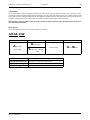
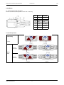
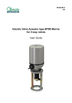
99.65.13-A
GB
Pneumatic actuators type AD and AS
Instruction
Pneumatic actuators type AD and AS
Instruction
GB
1. Summary
The actuator allows to conveniently open and close the valve fast in any places wherever the pneumatic pressure are connected and available. The Valve is designed to thoroughly assure the safety and convenience of users, however, please make
sure to operate after reading and digesting the User Manual completely. Please check the web site of Clorius Controls A/S
or inquire authorized agents for those items and subjects not described in the Instruction manual.
Data contained in the User Manual may be subject to change without advance notice for improvement of performance and safety of Product.
Model System
This is the A integrated user manual and the model is as follows.
A D 65 -HW
1
2
3
4
1
Adjust angle
(scotch-yoke)
2
3
4
Model number
Hand Wheel
Double acting
Spring return + double
acting
Drive method
Scotch-yoke
Angle adjustment direction
open/close - Simultaneous adjustment
Angle adjustment range
+5° / 90° / -10°
Temperature range
-20°C~80°C (option -40°C~200°C)
Clorius Controls A/S
2
Pneumatic actuators type AD and AS
Instruction
GB
2. Products
2.1. Internal Construction of Product
Internal construction of the product is illustrated as following:
No.
2-2. Product Operation
Double acting
Action A
Action A
(Fail open)
Spring
return
Action B
(Fail close)
Clorius Controls A/S
3
Part
Material
1
Body
Aluminum
2
Shaft
Steel alloy
3
Roller
Plastic
4
Crank
Steel alloy
5
Piston
Aluminum
6
Cover
Aluminum
Pneumatic actuators type AD and AS
Instruction
GB
3. Installation
User should execute the product installation after thoroughly digesting the following content.
3.1. Attachable Valve
The product can be applied to all Clorius Rotary type valve executing opening and closing actions rotating 90˚.
3.2. Selection of Actuator
Check the following items in advance when selecting the model of Actuator:
a. Required torque to open and close the Valve
b. Air pressure flowing into the Actuator
c. Operating Condition (Extremely Low Temperature, Extremely High Temperature)
User may attach the following Valve accessories as required:
a. solenoid valve
b. valve positioner (positioner indicator)
c. limit switch box
3.3. Caution during Installation
a. When installing the Product, execute the installation after either removing the potentially hazardous elements or
mounting the safety devices considering the accidents and danger that may be happen during the installation works.
b. The product can be used in any indoor and outdoor places except with the explosive environments.
c.
d.
CAUTION ! As for the Products weighing over 20 kg, the Label of below shown flowing may be attached, either
lifting by two persons or utilizing the appropriate device to move the product.
WARNING ! Do not inject air until the Product is completely mounted on the Valve during the installation process.
e. Do not inject air until the Product is completely mounted on the Valve. Free movement of installation tools is
required when installing the Product.
f. When attaching the Accessories, install after checking the Jointing Method and Joint Section.
g. Do never either use the hazardous substances or operate or store under the condition using hazardous substances.
Definition of hazardous substances are those potentially harmful materials, e.g. that may cause explosion or fire,
flammable materials, toxic materials, corrosive materials and etc.
Clorius Controls A/S
4
Pneumatic actuators type AD and AS
Instruction
GB
4. Operation
User of Product should operate upon fully recognizing the potential danger caused by the inappropriate management.
4-1. Operation
Operating medium: Compressed dry air
•
CAUTION ! If the ambient temperature is or may become lower than 5°C, filters for dehumidification should be
installed separately. The moisture inside the products is a direct cause of corrosion and failure.
• It is recommended that you should use purified air after eliminating dust and foreign substances in order to prolong
the life of the product.
• Do not use anything except the designated medium.
Pressure range: 4~6 kg/cm2
• The pressure should not exceed a maximum of 10kg/cm2 for the safety of users and for the life of the product.
4-2. Angle adjustment
There is an adjusting bolt which adjusts the open/close angle at the back of the products.
1
Headless wrench bolt
2
O-ring
3
Washer
4
Nut
Angle adjustment method (In case of standard-fail close)
• When you want to adjust the open position, put air in the left port or, if air is not available, rotate the shaft counterclockwise with a spanner to make it open. (When you want to adjust the close position, do it the other way round)
⇒ If you omit this process, you can not adjust a correct angle and therefore it cannot be assembled correctly, thus
causing a breakdown as the headless wrench bolt becomes bent.
• The left bolt is used to adjust the open position and the right bolt is used to adjust the close position. (When it is in
the fail-open position, do it the other way round.)
• Using a spanner or monkey wrench, unfasten the (4) nut slightly which you want to adjust.
• If you want to open or close it less, use a wrench to fasten the (1) bolt clockwise as required while checking the position of the valve.
• If you want to open or close it more, use a wrench to unfasten the (1) bolt slightly counterclockwise and check the
angle while turning the shaft with a spanner from time to time. ⇒ Even in case you want to make this product closed
completely to the maximum, it is safe to insert the bolt 1~2 threads more when the bolt touches the stopper. (Do
not pull the bolt out completely.)
• If you get the angle you want, fasten the (4) nut tightly by turning it clockwise.
• Put air in the left port and check if air leaks by pouring soapy water at the washer part before using it.
4-3. Caution during Operation
a. The product is designed to open and closed the Valve. Do not use the Product on the purposes other than specified
applications.
b. Ensure not to have the unskilled labors user the Product at own discretion.
c. Ensure to approach after completely securing the safety when the access to the Product under operation is desired.
d. When not using the Product over the long period of time, conceal the Air Injection Inlet in order to prevent the infiltration of moisture.
Clorius Controls A/S
5
Pneumatic actuators type AD and AS
Instruction
GB
5. Maintenance and Repair
5-1. Self Diagnosis
The actuator going through the high pressure test from the development stage, are to be individually and fully tested
prior to the shipment from factory. However, in the event the Product oftentimes does not operate with normal condition, execute the Self Diagnosis referring the below table. Nevertheless, if the trouble occurred is not still resolved,
contact Clorius Controls A/S or authorized Agents for customer service support.
Valve Not Working At All
Check
Remove
Actuator and
inject air.
Result
Working
Not working
Cause of Trouble
Troubleshooting
Torque of Valve is higher than that of
Actuator.
Install higher capacity model Actuator.
Injection air pressure too low.
Increase the Injection air pressure.
Check Actuator
1. Paste the soapy water with brush on
the shadowy area of the following,
and check the presence of air leakage to outside.
If the air is leaked or bubble is generated, contact the Customer Service
Center of Clorius Controls A/S to replace
the O-Ring or receive the Post Order
Service.
2. Paste the soapy water on Section B
of flowing injecting air into Inlet A,
and check the presence of bubble.
Clorius Controls A/S
Check the Air Injecting Pipe; Possibility
of clogging with foreign substances or
leaks.
Remove the foreign substances or
contact the Customer Service Center of
corresponding manufacturer for service.
Check the Solenoid Valve or electrical
devices; Possibility of disconnect or
unsuitable voltage.
Contact the Customer Service Center of
corresponding manufacturer for service.
6
Pneumatic actuators type AD and AS
Instruction
GB
When Valve is Closed Stopping the Opening Process
Check Item
Check the Actuator.
Check Other Connecting Sections.
Clorius Controls A/S
Cause of Trouble
Troubleshooting
Angle Adjusting Bolt turned inside
too excessively.
Use by properly adjusting the Bolt per
User’s need.
Injecting Air Pressure too low.
Increase the Injecting Air Pressure.
Torque of Valve is higher than that of
Actuator.
Install higher capacity model Actuator.
Force of Spring too weak for Spring
Return Model.
Contact the Customer Service Center
of Clorius Controls A/S or authorized
Agents.
Actuator Check. Refer to page 10.
In case of Air Leakage or presence of
bubble, contact the Customer Service
Center of Clorius Controls A/S to
receive the Post Order Service.
Check the Air Injecting Pipe.
Possibility of clogging with foreign
substances or leaks.
Remove the foreign substances or
contact the Customer Service Center
of corresponding manufacturer for
service.
Check the Solenoid Valve or electrical
devices. Possibility of disconnect or
unsuitable voltage.
Contact the Customer Service Center
of corresponding manufacturer for
service.
7
Clorius Controls A/S
Tempovej 27 · DK-2750 Ballerup · Denmark
Tel.: +45 77 32 31 30 · Fax: +45 77 32 31 31
E-mail: [email protected]
Web: www.cloriuscontrols.com