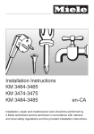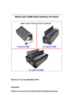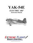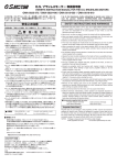
1
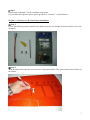
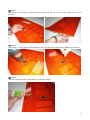
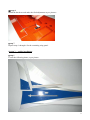
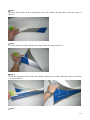
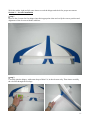
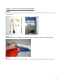
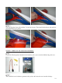
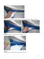
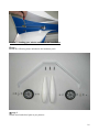
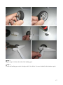
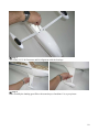
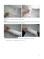
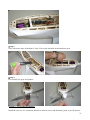
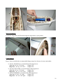
SebArt professional line SharkS 30E ARF ASSEMBLY MANUAL The Total Trainer SharkS 30E ARF, was designed by Italian Champion Sebastiano Silvestri. With this design SebArt reinvented the idea of the Trainer. This professional ARF kit is the result of more than 25 years in model airplane design experience. This innovative design combined with the extremely lightweight structure, all wood airframe, give the SharkS 30E an impressive precision and smoothness at any airspeed and flight condition. It is unbelievable how the SharkS 30E can do it all! It can fly very stable and easy at any airspeed: a dream for every beginner. In expert hands it can perform very easy reverse flight, hover, positive harrier, low speed knife edge, and almost anything else you can dream up are waiting you, and that for a Trainer is revolutionary! .....your SharkS is waiting you! Specifications Wing Span:..……….……........157 cm (61,8 in.) Length:……........….……….. 138 cm (54,33 in.) Wing Area:…….................. 44 dm2 (68,2 sq.in.) Weight:…...1.400 g. RTF less battery (49,26 oz) Radio:…..…...……4-Channel with 4 mini servo Recommended power set up: Motor:............................ Hacker A30-14L ESC:……………………. X40 SBec-Pro Battery: ….Flight Power 2500-3S or more Propeller: …….…...………. APC 14x7E Table of contents Table of contents...............................................................................................................……….. 2 Required radio, motor and battery.............................................................................................…. 3 Additional required items, tools and adhesives.............................................................................. 3 Warning.......................................................................................................................................... 3 Before starting assembly ...........................................................................................................… 3 Using the manual........................................................................................................................... 4 Warranty information…................................................................................................................. 4 Section 1 – ailerons installation...................................................................................................... 5 Section 2 – aileron servo & control horn installation…............................................................…. 7 Section 3 – rudder installation…………………………………..................................................... 9 Section 4 – elevator installation ………..…................................................................................... 11 Section 5 – elevator servo & control horn installation................................................................... 13 Section 6 – rudder servo & control horn installation…………………………………………….. 14 Section 7 – landing gear, wheels and “shark fin” installation…………………………………….16 Section 8 – electric motor installation …..…..…………................................................................19 Section 9 – final radio installation …………..................................................................................21 Wings installation............................................................................................................................ 21 Control throws................................................................................................................................ 21 Recommended CG......................................................................................................................….22 Range test your radio..................................................................................................................…. 22 2 Required radio, motor and battery Radio equipment: • Minimum 4-channel radio system • 4 digital mini servo, recommended JR PROPO DS385 or DS381 • 2 servo extension 600mm, for elevator and rudder servo • 2 servo extension 200mm, for aileron servo Recommended electric motor for best performance: • Hacker A30-14L + X40 SBec-Pro controller + APC 14x7 E Recommended Li-Po battery pack for best performance: • Flight Power EVO 2500-3S.…..or more for longer duration Additional required item, tools and adhesives Tools: • • • • • Drill Drill bits: 1,5mm, 2mm, 3mm Phillips screwdriver Hobby knife Soldering iron Adhesives: • thin CA • medium CA Warning This RC aircraft is not a toy! If misused, it can cause serius bodily harm and damage to property. Fly only in open areas, preferably in official flying sites, following all instructions included with your radio and motor. This plane is a compromise between Aerobatics and 3D flying, and not a pylon racer. It is built with a very light structure and for this reason we hardly recommend: → Do NOT fly your airplane at high speed, because this may cause structural failures. Before starting assembly Before starting the assembly, remove each part from its bag and protection for a prior inspection. Closely inspect the fuselage, wing panels, rudder, and stabilizer for damage. If you find any damage or missing parts, contact the place of purchase. If you find any wrinkles in the covering, use a heat gun or covering iron to remove them. Use caution while working around areas where the covering material overlap to prevent separating the covers. 3 Using the manual This manual is divided into sections to help make assembly easier to understand and to provide breaks between each major section. In addition, check boxes () have been placed next to each step to keep track of each step completed. Steps with two boxes indicate that the step will require repeating, such as for a right or left wing panel, two servos, etc. Rember to take your time and follow the directions. Warranty information SebArt garantees this kit to be free from defects in both material and workmanship at the date of purchase. This warranty does not cover any parts damage by use or modification, and in no case shall SebArt’s liability exceed the original cost of the purchased kit. Further, SebArt reserve the right to change or modify this warranty without notice. In that SebArt has no control over the final assembly or material used for the final assembly, no liability shall be assumed or accepted for any damage of the final user-assembled product. By the act of using the product, the user accepts all resulting liability. If the buyer is not prepared to accept the liability associated with the use of this product, the buyer is advised to return this kit immediately in new and unused condition to the place of purchase. SebArt di Sebastiano Silvestri Via Trento 69/3 38017 Mezzolombardo (TN) – Italy www.sebart.it 4 Section 1 – ailerons installation step 1 Trial fit the three aileron hinges, included in the hardware pack, in their place and verify the correct position and alignment of the aileron with the wing panel. step 2 Carefully glue, with some drops of thin CA, each of the three hinges in the aileron. step 3 Locate the aileron and carefully glue, with some drops of thin CA, the hinges into the wing panel. 5 step 4 Work the aileron up and down some times to work the hinges and check for proper movement. step 5 Locate the anti-stall/lift generator, and with an hobby knife open the four small slots on top of the wing panel, as per picture. step 6 Install and glue with some drop of thin CA the anti-stall/lift generator on the wing panel, as per picture. step 7 ( BEGINNER OPTION ) Secure the aileron with a piece of transparent tape, as per picture. 6 step 8 Repeat steps 1 through 7 for the remaining wing panel. ( If you chose the beginner option, please go direct to “Section 3” of this manual ) Section 2 – aileron servo & control horn installation step 1 Locate the following items included in the hardware pack, one 200mm extension and the servo (not included). step 2 With an hobby knife open the servo bay into wing panel and the fibre glass control horn location in the aileron. 7 step 3 Install the servo hardware (gommets and eyelets) and put the servo into the wing panel, as per pictures. step 4 Drill using a 1,5mm drill bit, and install the servo into the wing panel using a Phillips screwdriver. step 5 Glue the fibreglass horn with medium CA into the aileron. 8 step 6 Install the hardware and make the final adjustment as per pictures. step 7 Repeat steps 1 through 6 for the remaining wing panel. Section 3 – rudder installation step 1 Locate the following items, as per picture. 9 step 2 Insert the three hinges in their appropriate slots of the rudder, and glue them with some drops of thin CA. step 3 Carefully locate the rudder and glue the hinges with some drops of thin CA. step 4 Check the alignment of the rudder and fuselage, than glue the rudder with some drops of medium CA, as per pictures. step 5 10 Work the rudder right and left some times to work the hinges and check for proper movement. Section 4 – elevator installation step 1 Insert in the elevator the four hinges into their appropriate slots and verify the correct position and alignment of the elevator with the stabilizer. step 2 Carefully glue the hinges, with some drops of thin CA, in the elevator only. Than insert carefully the elevator through the fuselage. 11 step 3 Insert carefully the stabiliser into fuselage space and check the alignment with the rudder. step 4 Locate the elevator hinges into the stabiliser. Glue carefully the hinges in the stabiliser with some drops of thin CA. step 5 Once satisfied with the alignment, glue carefully with thin CA the stabilizer at the fuselage. 12 Section 5 – elevator servo & control horn installation step 1 Locate the following items included in the hardware pack, servo extension 600mm long and servo (not included). step 2 Than install the servo hardware (gommets and eyelets) and locate the servo into the fuselage. step 3 Drill using a 1,5mm drill bit, and install the servo into the fuselage using a Phillips screwdriver. 13 step 4 Glue the fibreglass horn with medium CA into the elevator. Than install the hardware and make the final adjustment as per picture. Section 6 – rudder servo & control horn installation step 1 Locate the following items included in the hardware pack, servo extension 400mm long and servo. step 2 Than install the servo hardware (gommets and eyelets) and locate the servo into the fuselage. 14 step 3 Drill using a 1,5mm drill bit, and install the servo into the fuselage using a Phillips screwdriver. step 4 Glue the fibreglass horn with medium CA into the elevator. step 5 Install the hardware and make the final adjustment as per picture. 15 Section 7 – landing gear, wheels and “shark fin” installation step 1 Locate the following items included in the hardware pack. step 2 Install wheel and wheel pant as per pictures. 16 step 3 Repeat steps 2 for the other side of the landing gear. step 4 Locate the landing gear on the fuselage and fix it with the 3 screws included in the hardware pack. 17 step 5 Test fit the L.G. Lift Generator and his alignment with the fuselage. step 6 Glue carefully the landing gear fillet with some drops of medium CA, as per picture. 18 step 7 Repeat step 5 and 6 for the other side of the landing gear. step 8 With an hobby knife open the three slots in the cover on top of the fuselage. Than glue carefully the “shark fin” with some drops of medium CA, as per picture. Section 8 – electric motor installation We recommend to use HACKER motor, you need the following items (not included): • Hacker A30-14L + X40 controller + APC 14 x 7 E 19 step 1 Locate the motor and fix it with the four screws included in the motor hardware pack. step 2 Locate and fix the ESC and his switch as per picture. 20 step 3 Glue with some drops of medium CA the Velcro strip included in the hardware pack. step 4 Fix carefully the prop and spinner. Section 9 – final radio installation Install the receiver, two extension 200mm for aileron servos and the battery pack as per the picture. 21 Wings installation Locate the wing panels and fix them using the wing retainer, as per picture. Control throws Please, follow carefully the recommended linkage setups for ailerons, elevators and rudder. ¾ For the AILERON we recommend the following throws: Low rate: 20° up / 20° down Expo: 20% High rate: 40° up / 40° down Expo: 60% ¾ For the ELEVATOR we recommend the following throws: Low rate: 20° up / 20° down Expo: 20% High rate: 40 ° up / 40° down Expo: 60% ¾ For the RUDDER we recommend the following throws: Low rate: 30° left / 30° right Expo: 20% High rate: 40° left / 40° right Expo: 60% 22 Note: the Expo is (+) for JR systems, and (–) for Futaba systems Use the recommended expos to soften the feel of the model, expecially on high rates. The goal is to get the model to feel the same around neutral as it does on low rates. Recommended CG The recommended Center of Gravity location is 110mm behind the leading edge of the wing against the fuselage. Use the Flight Power battery pack, moving it forward or backward, to achieve the correct balance. Range test your radio • Before fly, be sure to range check your radio as manufacturer’s instruction manual of you radio-system recommand. • Double-check all controls (aileron,elevator, rudder and throttle) move in the correct direction. • Be sure that your Flight Power batteries are fully charged, as per the instructions and that your radio is fully charged as per its instructions. Finally... have a nice flight! SebArt di Sebastiano Silvestri Via Trento 69/3 38017 Mezzolombardo (TN) – Italy www.sebart.it 23