1
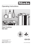
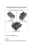
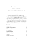
Installation Instructions
KM 3464-3465
KM 3474-3475
KM 3484-3485
en-CA
Installation, repair and maintenance work should be performed by
a Miele authorized service technician in accordance with national
and local safety regulations and the provided installation instructions.
IMPORTANT SAFETY INSTRUCTIONS
Installation
The minimum distances given in
these Installation instructions are to
combustible surfaces, and must be
observed to ensure safe operation.
Failure to do so increases the risk of
fire.
The cabinetry and venting hood
should be installed first to prevent
damage to the cooktop.
recommended
Gas appliances should only be
installed in a well ventilated area.
The countertop must be bonded
with heat resistant (212 °F/100 °C)
adhesive to prevent distortion or
dissolving.
The cooktop should only be
installed as shown in the
illustrations while maintaining the
required safety distances shown. Do
not install the cooktop between two tall
cabinets, this is a fire hazard.
not recommended
a = indicates cooktop cut-out
b = minimum distance between
cut-out and a tall cabinet:
12" (305 mm)
This appliance has not been
designed for maritime use or for
use in mobile installations such as
recreational vehicles or aircraft.
However, under certain conditions it
may be possible for installation in these
applications. Please contact the Miele
Technical Service Department with
specific requirements.
22
not allowed
IMPORTANT SAFETY INSTRUCTIONS
The cooktop must not be installed
over a dishwasher, washer, dryer,
refrigerator or freezer. Heat radiated by
the cooktop may damage the
appliances.
Safety distances above the
appliance
Deep fat fryers must not be
installed next to gas cooktops. Gas
flames can ignite splattering oil. A
distance of at least 12" (305 mm)
should be maintained between these
two appliances. The minimum distance
between two cooktops must be 4"
(100 mm).
Install the appliance so that the
power cord or gas piping does not
come into contact with any portion of
the cooktop which may become hot
during use.
This appliance must be installed
with its own shut off valve and the
included gas pressure regulator.
Both the valve and the regulator
must be easily accessible to the
consumer after the appliance is
installed.
This appliance must be
disconnected from the gas supply
during any pressure testing of the
system performed in excess of
1
/2 psi (3.5 kPa). This appliance
must be isolated at test pressures
equal to or less than 1/2 psi
(3.5 kPa).
There must be a safety distance of at
least 30" (760 mm), c between the
appliance and any objects above it.
The overhead cabinet depth, d, if
unprotected, must not exceed 13"
(330 mm). The minimum distance of
combustible surfaces located above
and to the sides of the cooktop, e, is
18" (457 mm).
If the cabinet manufacturer
recommends a greater distance, follow
that manufacturers recommendation.
When installing the cooktop under a
venting hood, always observe the
minimum distance recommended by
the hood manufacturer.
Keep this instruction book in a safe
place for reference and pass it on to
any future user.
Any pipe connections must be made
using a thread sealant approved for
gas connections. Failure to correctly
install these items could lead to a
gas leak and subsequent explosion.
23
Appliance dimensions
KM 3464 / KM 3465
b
30
21 5/16" + 1/1
- 6"
(542 +
- 1mm)
"
/16
-1
+
(762
+ 1mm)
"
3/8
mm
9
-
2 5/16"
(58m
m)
6"
/1
ß3
)
mm
(
0 2 3/4
"
)
(0 7
0mm
4
ßR
6"
+1/1
"
/8
m)
(51
8 + 1 "- 1/16" 8 3 +-1m
0
m
- m)
2 (72
20 3/8 +
0 1 7/8 a
"
(0 4
7mm
)
0 2
5"
6
(0
35m
m)
a
6"
1
3/
c
4"
1/
3
m)
3m
(8
d
0 1 mm)
(0
8 7/16"
(215
mm)
6"
)
m
9m
/1
20
2
11
(6
6"
3 m)
m
(78
1/1
a Front
b Built-in depth
c Gas connection R ½" NPT
d Mains connection box
24
2"
)
1/
m
7 190m
(
Appliance dimensions
KM 3474 / KM 3475
21 5/16" +1/1
- 6"
(542 + 1
- mm)
"
+ 1/16
36 -
+1 mm)
(914
25/16"
(58m
m)
"
3/8 )
m
(9m
"
/16 )
3
ß 4mm
R
(ß
b
0 2 3/4
(0 7
"
0mm
20 3/8" +
-1/16"
8 +- 1
mm
)
(51
(0
2
635 5"
mm
5-
3
9-
(88
b
3 3/8"
(86mm)
a
"
/16 )
0
m)
+1 m
0 17/8
"
(0 4
)
3
01
"
16
+1/
)
7mm
)
a
"
7/8
m)
6m
2
2
(
8
d
6"
1/1 )
3 mm
(78
c
m
m
20
7 5/16
5mm "
)
"
16
)
9/
5 42mm
(1
(18
6" )
/1 m
1170m
6 (1
/8"
31 mm)
(80
a Front
b Built-in depth
c Gas connection R ½" NPT
d Mains connection box
25
Appliance dimensions
KM 3484 / KM 3485
21 5/16" +- 1/1
6"
(542 +-1
mm)
"
+1/16
1/2"
+ 1mm)
42
9(107
2 5/16"
(58m
m)
)
mm
(9
"
/16 )
3
ß mm
4
(ß R
b
0 2 3/
4"
07
0m
m
/2"
1
20 3/8
"+
- 1/16"
8 +- 1
mm
)
02
( 06
41
m)
+1 m
54-
(10
5"
a
0 17/
8"
( 04
7mm
)
35m
m)
b
"
/16
a
)
3
0 1 0mm
(0
"
16
+ 1/
(51
d
9"
m)
8m
(22
c
3 3/8"
8 11/16
)
"
/16
31 mm)
(78
a Front
b Built-in depth
c Gas connection R ½" NPT
"
1/8
"
0mm
d Mains connection box
"
1/4 )
mm
(83
3
(86mm)
2
(22
26
"
3/8
6"
7/1 )
3 mm
7
(8
12
)
(3
m
5m
,
07
Installation
^ Prepare the work top cut-out as
shown in the diagram.
Rember to maintain the minimum
safety distances to combustible
surfaces:
- 2 3/4" (70 mm) between the cut-out
and the back wall and
- 12" (305 mm) between the cut-out
and a side wall or tall unit to the right
or left of the cut-out.
(See "Important Safety instructions").
^ Seal the cut surfaces with a suitable
heat-resistant sealant to avoid
swelling caused by moisture.
If during installation, the corners of
the frame are not flush with the work
top surface, the corner radius (max.
3
/16" [4 mm]) can be carefully filed to
fit.
27
Installation
Setting the cooktop into place
Securing the cooktop
^ Secure the cooktop with the included
fixing bracket.
Countertop 13/16" (20 mm)
d
c
^ After removing the protective
backing, d, stick the supplied seal,
c, under the edge of the cooktop.
^ Screw the gas regulator onto the
nipple underneath the cooktop. (See
“Gas Connection - Gas pressure
regulator”.)
^ Feed the power cord through the
cut-out to the power outlet.
^ Set the cooktop in the cut-out and
center it.
Install the appliance so that the
power cord and gas piping does not
come in contact with any portion of
the cooktop which may become hot
during use.
28
Countertop 1 9/16" (40 mm)
Installation
Sealing
The cooktop must not be permanently
sealed into the countertop when
installed. The sealing strip under the
edge of the cooktop provides a
sufficient enough seal.
If the cooktop is sealed into position,
the countertop or the appliance may
be damaged if the cooktop needs to
be removed for maintenance or
service.
29
Electrical connection
This appliance must be grounded
according to local or national codes.
All electrical work should be
performed by a qualified electrician
in accordance with local codes and
with the:
-
National Electrical Code
ANSI / NFPA No. 70
for the USA
or
- Canadian Electrical Code Part I
for Canada
(CSA Standard C 22.1).
,WARNING
Disconnect the appliance from the
main power supply before
installation or service. To reduce the
risk of electric shock, make sure that
the appliance is properly grounded
after installation.
This appliance is equipped with a
three-prong grounding plug to
prevent shock hazards. It should be
plugged directly into a properly
grounded outlet. Do not cut or
remove the grounding prong from
the plug. If the plug does not fit the
outlet, have the proper outlet
installed by a licensed electrician.
To guarantee the electrical safety of
this appliance, continuity must exist
between the appliance and an
effective grounding system. It is
imperative that this basic safety
requirement be met. If there is any
doubt, have the electrical system of
the house checked by a qualified
electrician.
The manufacturer cannot be held
responsible for damages caused by
the lack, or inadequacy, of an
effective grounding system.
Power supply
The automatic ignition requires that the
cooktop be connected to a 120 VAC,
60 Hz power supply. The supply line
should be protected by a 15 A fuse.
Actual power consumption (during
ignition only) is 25 W.
This appliance is equipped with a 4 ft.
(1.2 m) long power cord that is ready
for connection to the appropriate outlet.
Place the power outlet so that it is
accessible after the appliance has
been installed in the countertop.
30
Note to the installer
Please leave these instructions with the
consumer or the appliance.
Electrical connection
Wiring diagram
,Caution: Label all wires prior to disconnection when servicing controls.
Wiring errors can cause improper and dangerous operation.
Verify proper operation after servicing.
31
Gas connection
Installation and service must be
performed by a qualified installer,
service agency or gas supplier.
The gas connection must be made
in accordance with local codes or, in
the absence of local codes, with
In Massachusetts a licensed
plumber / gas fitter is required.
-
This appliance must be installed
with its own shut off valve and the
included gas pressure regulator.
Both the valve and the regulator
must be easily accessible to the
consumer to turn on or shut off the
gas supply after the appliance is
installed.
or
- the current Can / CGA B 149.1
and .2 Installation Codes for gas
burning appliances for Canada.
This appliance and its individual
shut off valve must be disconnected
from the gas supply during any
pressure testing of that system
performed in excess of ½ psi
(3.5 kPa). The appliance must be
isolated from the gas supply line by
closing its individual manual shut off
valve at test pressures equal to or
less than ½ psi (3.5 kPa).
Any pipe connections must be made
using a thread sealant approved for
gas connections. Failure to correctly
install these items could lead to a
gas leak and subsequent explosion.
32
the National Fuel Gas Code,
ANSI Z 21.1 / NFPA 54
for the USA
Make sure that the maximum gas
supply pressure before the gas
pressure regulator is never more than ½
psi for both natural gas or LP gas.
The minimum required gas pressure to
get the required gas input is
4" w.c. for natural gas
10" w.c. for LP gas.
Gas connection
Gas pressure regulator
A pressure regulator that is convertible
from natural to LP gas (Propane) or vice
versa is included with the appliance.
The included regulator corresponds
with the gas type of the cooktop. Verify
before installing.
The adjusted pressure is:
natural gas - 4" w.c.
LP gas - 10" w.c.
For convenience, an AGA or CGA
approved flexible stainless steel gas
hose (accordion type) may be used
between the gas connection and the
regulator. This will allow the appliance
to be lifted out of the countertop for
cleaning or servicing. Make sure that
any drawers, cabinet doors, etc., do not
rub on this gas hose.
Do not use any regulator unless it
has been supplied by Miele. Doing
so may cause a gas leak.
If there is any doubt concerning
installation contact the Miele Technical
Service Department:
U 1-800-999-1360
[email protected]
V 1-800-565-6435
[email protected]
a Cooktop
b ½" NPT
c Regulator
As shown in the above diagram, the
included regulator must be used when
connecting the Miele cooktop to your
gas supply. This item has been
customized by Miele to meet all
applicable safety requirements. Make
sure the regulator is easily accessible
for adjustment after the appliance has
been installed.
After connecting the appliance check
all fittings for gas leaks e.g. with
soapy water.
When installed properly, the flame will
be steady and quiet. It will also have a
sharp, blue inner core that will vary in
length proportional to the burner size.
Flame adjustment will not be necessary.
33
Gas connection
Nominal Rating Table
KM 3464 / KM 3465 KM 3474 / KM 3475 KM 3484 / KM 3485
NG / LP-Gas
Normal burner
NG / LP-Gas
NG / LP-Gas
BTU/hr
kW
BTU/hr
kW
BTU/hr
kW
Max. output
9,000
2.6
9,000
2.6
9,000
2.6
Min. output
1,700
0.50
1,700
0.50
1,700
0.5
Max. output
12,000
3.5
12,000
3.5
12,000
3.5
Min. output
2,500
0.73
2,500
0.73
2,500
0.73
Max. output
15,300
4.5
15,300
4.5
15,300
4.5
Min. output
620
0.18
620
0.18
620
0.18
Max. output
-
-
15,300
4.5
16,500
4.8
Min. output
-
-
620
0.18
620
0.18
45,300
13.2
60,600
17.7
73,800
21.6
Fast burner
Wok burner left
Wok burner
right
All burners
Max. output
34
Converting to another type of gas
The cooktop should have been ordered
for connection to either natural or LP
gas.
If the cooktop is not configured for the
proper type of gas connection please
contact your Miele Dealer.
35
Alterations rights reserved / 0107
M.-Nr. 06 818 490 / 04
en - USA