1
SPECIFICATIONS
- Battery: NiCd 7V 0,75Ah
BEGHELLI LOGICA® CONTROL UNIT
- Power supply voltage: 230V~50Hz
- Max. input from mains: 10Va
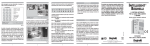
Control unit for centralised management and control of
lighting and emergency lighting appliances
W ARNINGS / W ARRANTIES
- Before connecting this appliance, check that the rating plate data correspond to the mains data.
- This appliance must be used solely for the purpose for which it was built.
Any other use is to be considered as improper, and may cause damage. The
manufacturer will not be liable for any damage to human beings, animals
or properties caused by improper, wrong or unreasonable use.
- Before any cleaning or maintenance operation, disconnect the appliance
from the mains.
- The product cannot be disposed as unsorted municipal waste. It must be
collected separately to prevent negative environmental impacts. In accordance with the procedures of Directive 2002/96 and relevant national laws
and regulations adopted pursuant to this Directive on the disposal of waste
at the end of the life cycle of the product, any violation is sanctioned by law.
- Beghelli products are covered by laws on intellectual property.
- Should any repairs be necessary, contact an authorised service centre
and always request the use of original spare parts. Failure to comply with
the above may undermine the safety of the appliance.
334.900.395 A
- For repairs/replacements under guarantee contact an Authorised Dealer.
www.beghelli.com
BEGHELLI S.p.A. - Via Mozzeghine 13, 15 - 40050 MONTEVEGLIO (BO)
Tel. 051 9660411 - Fax 051 9660444
INSTRUCTIONS
FOR USE AND INSTALLATION
WHAT IS THE BEGHELLI LOGICA CONTROL UNIT
INDEX
The Logica control unit has been designed to dialogue with different communication protocols. It enables the simultaneous management of both lighting and emergency lighting appliances. As well as the various functions
dedicated to testing and controlling emergency lighting, the Logica control
unit can command individual appliances or groups of lamps using the DALI
protocol (the international protocol that complies with IEC standard 60929).
The control unit also allows the creation of customised "scenes" for controlling
the type of lighting according to the varying lighting requirements at different
times of the day. It is also possible to adjust the brightness using a dimmer
for single appliances or groups, even when fitted with a timer or connected
to light sensors, which makes it possible to light rooms or areas in the most
similar way to natural sunlight (biodynamic lighting).
• WHAT IS THE BEGHELLI LOGICA CONTROL UNIT
page
3
• APPLIANCE FUNCTION
page
3
Wiring diagram
page
4
Groups and scenes
page
5
Menu
page
5
Password
page
6
Initial menu
page
6
page
6
page
7
page
10
manual test 3-1
page
10
emergency function and management 3-2
page
11
error status 3-3
page
12
management test 3-4
page
13
management lamp 3-5
page
14
management group 3-6
page
15
control unit management 3-7
page
17
configuration management 3-8
page
19
APPLIANCE FUNCTION
page
19
• SPECIFICATIONS
page
20
The control unit manages and controls the status of the programmed appliances, controls routine tests according to the modes set by the user and can
perform a vast series of manual operations that can be selected from a series
of menus accessible from the keyboard.
• WARNINGS / WARRANTIES
page
20
“Activate scene” menu 1
“Light” menu 2
“Maintenance” menu 3
“status MSG” menu 4
2
The control unit is composed of a keyboard+display for all user operations,
four programmable switches for light activation, an RS485 input for remote
connection and the DALI-compatible bus input for managing the system.
The control unit houses the bus' built-in feeder and can autonomously manage a complete system comprising 128 appliances without requiring further
equipment.
If the local switches are used the normally open buttons must be employed.
3
GROUPS AND SCENES
WIRING DIAGRAM
+UX -UX COM BUS 485
P
N
D
A
NOT POLARIZED
COM
-UX
+UX
MAINS
P
N SUPPLY
A scene is a preset coordinated lighting combination that involves several
appliances.
GND
RS485
SWITCHES
4 3 2 1
A
DALI
All the appliances programmed can be associated to 16 groups; each device may pertain to one or more groups or none at all. These groups can enable specific operations on subsets of the system.
D
MAX 128 LOGICA
MAX 128 UNITS
SWITCH
MAX 64 DALI
By giving the system the order to go to scene "xx" (from 1 to 16), each lighting appliance goes to a particular internally stored brightness condition.
Given that this value is independent for each lighting appliance, preset lighting situations can be created and performed simultaneously, thus combining
in a single command many lighting settings for different appliances.
For each scene it is possible to decide that the appliance will switch on,
switch off, go to a given brightness percentage, or do nothing at all, ignoring
the order and remaining in the current state of brightness.
MAX 255
CONTROL UNIT
MENU
D
COM
-UX
+UX
MAINS
P
N SUPPLY
NOT POLARIZED
The user can decide to protect the settings programmed activating a
password.
RS485
GND
A
All control unit functions can be accessed from menus: a first level enables
a general overview of the system, activates lights or preset lighting scenes;
in a second level it is possible to set, program and modify the setting of the
plant.
SWITCHES
4 3 2 1
A
DALI
D
D
C
The menus can be scrolled "vertically" using the arrows
and
; by pressing B one selects the item currently displayed; by pressing A one moves
up a level. The display back-light is activated when any key is pressed.
To generate a manual test proceed as follows:
• select the "manual test" menu;
• select the appliance or group of appliances or even the entire system on
which the operation is to be performed;
• select the operation to be performed, for instance "functional test";
• press B; the operation will now be performed and the control unit is
ready to receive new commands.
SWITCH
4
5
PASSWORD
“Lights 2” Menu
In order to avoid a not intentional reset of the plant and to protect settings
and the parameters of that one, a password can be activated.
This menu enables switching on, switching off or dimming individual lighting
appliances, groups of appliances or the entire system.
When one enters the third level of the menu it is possible to modify brightness
directly, in real time, by using the
and
buttons:
• a brief pressing of the
key switches on the appliances at maximum brightness;
• a brief pressing of the
key switches the appliances off;
• a prolonged pressing of the
or
keys causes a slow variation of
brightness in the chosen direction. Finally, by releasing the key, the luminaires maintain the brightness achieved, between the 14 pre-set possible
intensities.
If the User tries to enter in a menu the password is requested and will then
be allowed access for 4 minutes. Should operations last longer than 4 minutes, the User will be required to enter the password again.
C
INITIAL MENU
The "Initial menu" enables the User to use previously entered settings,
manage lights, check the overall state of the system.
There are four possible options:
- ACTIVE SCENE 1 - makes it possible to select and activate one of the 16 preset scenes.
- L I G H T S 2 - makes it possible to activate any appliance and to switch it on,
switch it off and dimmer it.
- M A I N T E N A N C E 3 - enables access, protected by a password, to all the setting and programming functions reserved for system fitters.
- S T A T U S M S G 4 - displays all the control unit status messages currently
active.
“Active scene 1” Menu
This menu enables the activating of the preset lighting scenes.
ACTIVE SCENE 1
B ACTIVE SCENE 01
C ACTIVE SCENE 02
1-1
1-1
Choose the scene to be activated from 01 to 16 and press B to confirm.
SCENE ACTIVATE
Use the "lights menu" to programme the "scenes".
D
D
C
D
LIGHTS 2
B ALL 2-1
B ALL
C SWITCH OFF
B SET IN SCENE 01
D DEL IN SCENE 16
C
2-1-1
2-1-1
2-1-1-1
2-1-1-2
choose scene from 01 to 16 and press B to confirm.
SCENE STORED
SCENE DELETED
D SWITCH ON (MAX)
B SET IN SCENE 01
D DEL IN SCENE 16
SCENE STORED
SCENE DELETED
pressed
D
or
2-1-1
2-1-1-1
2-1-1-2
C
STEP DIMMER 8
B SET IN SCENE 01
D DEL IN SCENE 16
choose scene from 01 to 16 with
2-1-1
C
2-1-1-1
2-1-1-2
or
SCENE STORED
SCENE DELETED
6
7
D and press B to confirm.
B
LOGICA
2-2
B LOG ----
choose the lamp with
C SWITCH
C
SCENE STORED
SCENE DELETED
2-2-1
or
D SWITCH
D and press B to confirm.
OFF
2-2-1
B SET IN SCENE 01 2-2-1-1
D DEL IN SCENE 16 2-2-1-2
choose scene from 01 to 16 with
C
or
ON (MAX)
B SET IN SCENE 01
D DEL IN SCENE 16
choose scene from 01 to 16 with
D and press B to confirm.
SCENE STORED
SCENE DELETED
C
or
D and press B to confirm.
SCENE STORED
SCENE DELETED
pressed
D
or
STEP DIMMER 8 2-2-1
B SET IN SCENE 01 2-2-1-1
D DEL IN SCENE 16 2-2-1-2
choose scene from 01 to 16 with
C
or
D and press B to confirm.
SCENE STORED
SCENE DELETED
B
DALI -2-3
B DALI --
choose the lamp with
C SWITCH
C
2-3-1
C
2-3-1-1
2-3-1-2
or
D and press B to confirm.
GROUP 01
B GROUP 01
2-4
2-4-1
Choose the group from 01 to 16 with
C SWITCH
C
OFF
2-4-1
B SET IN SCENE 01
D DEL IN SCENE 16
C
or
or
D and press B to confirm.
2-4-1-1
2-4-1-2
D and press B to confirm.
SCENE STORED
SCENE DELETED
D and press B to confirm.
OFF
2-3-1
B SET IN SCENE 01 2-3-1-1
D DEL IN SCENE 16 2-3-1-2
choose scene from 01 to 16 with
D and press B to confirm.
SCENE STORED
SCENE DELETED
choose scene from 01 to 16 with
2-3-1
or
choose scene from 01 to 16 with
B
C
or
D oC
STEP DIMMER 8
B SET IN SCENE 01
D DEL IN SCENE 16
D SWITCH
choose scene from 01 to 16 with
C
2-3-1-1
2-3-1-2
SCENE STORED
SCENE DELETED
pressed
ON (MAX) 2-2-1
B SET IN SCENE 01 2-2-1-1
D DEL IN SCENE 16 2-2-1-2
2-3-1
C
or
8
D and press B to confirm.
D SWITCH
ON (MAX)
B SET IN SCENE 01
D DEL IN SCENE 16
choose scene from 01 to 16 with
2-4-1
C
2-4-1-1
2-4-1-2
or
SCENE STORED
SCENE DELETED
9
D and press B to confirm.
pressed
D
or
C
choose the time with
STEP DIMMER 8
B SET IN SCENE 01
D DEL IN SCENE 16
choose scene from 01 to 16 with
2-4-1
C
D and press B to confirm.
SCENE STORED
SCENE DELETED
“Maintenance 3” menu
All "Maintenance" menus are password-protected.
In the "maintenance menu - manual test 3-1" it is possible to perform and
interrupt manual tests on individual appliances, groups or the entire system.
One can give different test commands on different appliances, without waiting
for the first to finish before starting the subsequent ones; the lamp that receives
a test start (see “Functional” 3-1-1-2) autonomously proceeds for the necessary time (30 sec), without requiring the control unit, thus giving the opportunity
to control other tests on other lamps.
MAINTENANCE
3
3-1
B MANUAL TEST
B ALL
B STOP TEST
C FUNCTIONAL
C SWITCH ON INC.
C 00 h 0 0 m i n 0 0 s e c
choose the time with
C
or
3-1-3
3-1-3-1
3-1-3-2
3-1-3-3
3-1-3-4
C FUNCTIONAL
C SWITCH ON INC.
C 00 h 0 0 m i n 0 0 s e c
choose the time with
C
or
D and press B to confirm.
COMMAND EXECUTED
The unconditioned on function entails the switching on of the emergency
lamps powered by battery even in the presence of mains power, without preset duration, in which the charge level of the battery is not under examination; it is interrupted when the battery is completely run down or by sending
a "stop test" command. The autonomy test is associated to the duration that
it must have. This duration is at the User's discretion and can be selected by
scrolling the menu downwards. This manual test does not in any way modify
the timing and the durations set for the automatic tests.
3-1-2-1
3-1-2-2
3-1-2-3
3-1-2-4
MAINTENANCE
3
3-2
B EMERGENCY
3-2-1
B ALL
3-2-1-1
B EMERG. ENABLED
E
M
E
R
G
.
U
N
E
N
A
B
L
E
3-2-1-2
C
3-2-1-3
C SWITCH OFF
B COMMAND EXECUTED
3-1-2
10
B GROUP 01
B STOP TEST
3-1-1-1
3-1-1-2
3-1-1-3
3-1-1-4
D and press B to confirm.
C FUNCTIONAL
C SWITCH ON INC.
C 00 h 0 0 m i n 0 0 s e c
D and press B to confirm.
In the "Maintenance menu - Emergency (Management) 3-2" it is possible to inhibit or enable the emergency condition for individual LOGICA
appliances, groups or the entire system.
It is not possible to permanently inhibit the emergency function or to programme inhibition for the next blackout: each appliance can be inhibited or
enabled only if already in blackout conditions, otherwise the command will
be rejected.
3-1-1
COMMAND EXECUTED
B LOGICA ---B STOP TEST
or
COMMAND EXECUTED
2-4-1-1
2-4-1-2
or
C
11
B
LOGICA ---3-2-2
3-2-2-1
B EMERG. ENABLED
E
M
E
R
G
.
U
N
E
N
A
B
L
E
3-2-2-2
C
3-2-2-3
C SWITCH OFF
B COMMAND EXECUTED
B
GROUP 01
3-2-3
3-2-3-1
B EMERG. ENABLED
E
M
E
R
G
.
U
N
E
N
A
B
L
E
3-2-3-2
C
3-2-3-3
C SWITCH OFF
B COMMAND EXECUTED
In the "Maintenance menu - Management Test 3-4" it is possible to set
the timings and the frequency of the automatic tests of the emergency
part of the system: it is possible to select when to perform the next functional/autonomy test and every how many days to perform the subsequent
ones (periodicity of tests); furthermore it is possible to break the system
down into odd and even lights in order to make them perform autonomy tests
seven days apart (odd before, even 7 days later).
The tests cannot be inhibited.
MAINTENANCE
3
B TEST MANAGEMENT
B
B
NEXT FUNCTIONAL TEST 3-4-1
--- DAYS
Whereas the enable/disable functions are reversible, the off function is irreversible, unless the mains power comes back on: it is useful to maintain the
charge of the light accumulators and, if referred to the entire system, it is used
to disable it in the event of particularly lengthy maintenance operations.
When the operations have been completed, the control unit switches off and
in order to change status again the mains supply must come back on.
choose with
In the "Maintenance menu - Error status 3-3" it is possible to see whether
there are error conditions present on the Logica and DALI appliances, obtain
information about the error conditions and any components that require
replacing, and to cancel any error condition indicated.
choose with
MAINTENANCE
3
B ERROR STATUS
B NONE ERRORS
D and C
B
choose with
D and C
D and C
B
3-3-1
For each appliance, only the errors currently in the memory will appear, as well
as the possibility to cancel them.
In the event of the selection of groups of appliances or the entire system,
the possibility of cancelling errors only is given without further details.
In order to display the details concerning certain errors of Logica luminaires
only, press B; you will receive further information on type of battery or tube
which has an eventual failure.
12
choose with
D
B
choose with
B
3-4-2
3-4-2-1
then press B to confirm.
-- HOURS
and
C
3-4-2-1
then press B to confirm.
-- MINUTES
D and C
D and C
3-4-1-1
3-4-1-1
then press B to confirm.
3-4-2-1
then press B to confirm.
FUNC.TEST PERIOD
--- DAYS
B
choose with
B
then press B to confirm.
NEXT AUT. TEST
--- DAYS
B
choose with
3-3
3-4-1-1
3-4-1-1
XXX DAYS XX HOURS
-- MINUTES
D and C
3-4-1-1
then press B to confirm.
XXX DAYS
-- HOURS
B
B
3-4
3-4-3
3-4-3-1
then press B to confirm.
AUT.TEST PERIOD
B --- DAYS
3-4-4
3-4-4-1
13
choose with
B
D and C
then press B to confirm.
B
EVEN ODD TEST
3-4-5
C
O
N
T
E
M
P
O
R
A
R
Y
3-4-5-1
C
3-4-5-2
C 7 DAYS DEFERRED
choose with
D and C
B
then press B to confirm.
COMMAND EXECUTED
In the “Maintenance menu – Management Lamps 3-5” it is possible to evaluate the current status of each Logica luminaire (or group) and modify the
settings (e.g. autonomy 1h or 3h the even or odd status…).
The information on the luminaire relate to the Software version, the programming conditions, Autonomy 1 or 3 hours, even and odd status, the presence of main supply, emergency operation inhibition/enabling, the test
in progress or postponed condition, the presence of errors and the settings
for SA (maintained) luminaires.
B
LOGICA XXXX SA
B ID SW XXX . X
C PROGRAMMED
C AUTONOMY 3H
C ODD FITTING
C MAIN ON
C EMERG. ENABLED
C NO TEST ON
C NO TEST SUSPEN.
C NONE ERRORS
C CENTRALDIMMER
C FUNCTION PS
3-5-2
GROUP 01
3-5-3
choose with
MAINTENANCE
3
F
I
T
T
I
N
G
M
A
N
AGEM.
3-5
B
B ALL
B ID SW ---.C NOT PROG/PROG
C 1H/3H
C EVEN/ODD
C -----------C EM. ENAB/UNEN
C STOP TEST
C DEL TEST SUSP.
C DEL ERRORS
C SELF DIMMER
C FUNCT. SA/PS
D
B
3-5-1
(?)
(?)
(?)
(?)
(?)
(?)
(?)
(?)
(?)
14
3-5-1-1
3-5-1-2
3-5-1-3
3-5-1-4
3-5-1-5
3-5-1-6
3-5-1-7
3-5-1-8
3-5-1-9
3-5-1-10
3-5-1-11
and
C
3-5-2-1
3-5-2-2
3-5-2-3
3-5-2-4
3-5-2-5
3-5-2-6
3-5-2-7
3-5-2-8
3-5-2-9
3-5-2-10
3-5-2-11
then press B to confirm.
ID SW ---.C NOT PROG/PROG
C 1H/3H
C EVEN/ODD
C -----------C EM. ENAB/UNEN
C STOP TEST
C DEL TEST SUSP.
C DEL ERRORS
C SELF DIMMER
C FUNCT. SA/PS
(?)
(?)
(?)
(?)
(?)
(?)
(?)
(?)
(?)
3-5-3-1
3-5-3-2
3-5-3-3
3-5-3-4
3-5-3-5
3-5-3-6
3-5-3-7
3-5-3-8
3-5-3-9
3-5-3-10
3-5-3-11
In the "Maintenance menu - Management groups 3-6" it is possible to assign each appliance or switch (local) to one or more groups or to none at all,
in a totally free and unrestrictive way. There are 16 groups available, there is
no obligation to start from the lowest numbers.
15
At the last level of this menu 16 figures will be displayed (0 or 1): by going
towards the right you can select the "x" group (numbered from 1 to 16 from left
to right) and with the keys
and
you can pass from the figure "0" to "1"
and vice versa. The figure "1" identifies the belonging to the selected group.
D
C
An appliance can therefore also have all "1" (belongs to all groups), just some
or none, so as to be completely independent from the other appliances.
The local switches (four) are managed in the same way: they are assigned
to one or more groups; when a button is pressed the action (on/off/dimmer)
addresses all the lamps that belong to the groups that the pressed button
belongs to. This management concerns the entire lighting and emergency
lighting system, and therefore both the DALI and Logica appliances.
MAINTENANCE
3
B G R O U P M A N A G E M E N T 3-6
3-6-1
B ALL
1
0
0
1
0
0
0
1
0
0
1
1
1
0
1
1
B
choose 1 with the
B
B
D key and 0 with the C
DALI -3-6-3
1
0
0
1
0
0
0
1
0
0
1
1
1
0
1
1
B
choose 1 with the
B
D
key and 0 with the
SWITCH 1
choose 1÷4 with the keys
B
3-6-3-1
C
key.
3-6-4-1
D key and 0 with the C
choose 1÷16 with the keys
key.
3-6-5
D and C.
1111111111111111
3-6-5-1
16
CHANGE DATE - HOUR
B 2005-07-01 11:30
choose with
B
D and C
B
3-7-2-1
then press B to confirm.
3-7-3
-------
CHANGE ADDRESS
B ADDRESS 000
3-7-4
choose numbers with
B
3-7-2
CHANGE PASSWORD
B OLD PASSWORD
B NEW PASSWORD
choose numbers with
B
D and C.
GROUP 01
B
key.
3-6-4
1111111111111111
choose 1 with the
B
key.
key.
MAINTENANCE
3
3-7
B C.U MANAGEMENT
3-7-1
B PASSWORD ON/OFF
P
A
S
S
W
O
R
D
O
N
/
P
A
S
S
W
ORD OFF 3-7-1-1
B
3-6-1-1
D key and 0 with the C
D key and 0 with the C
In the “Maintenance menu-Control unit management 3-7” it is possible
to set current Date/Time, enable or modify the password, set the remote
address of the Control Unit (in the case of multiple systems), order printouts (in the case of local printers) set and configure the type of Inputs (4 local
switches).
B
LOGICA ---3-6-2
1
0
0
1
0
0
0
1
0
0
1
1
1
0
1
1
3-6-2-1
B
choose 1 with the
choose 1 with the
D and C
D and C
keys then press B to confirm.
3-7-4-1
keys then press B to confirm.
LOCAL PRINTER
3-7-5
B NOT PRESENT/PRESENT
PRINT 3-7-6
B NONE PRINT*
3-7-5-1
3-7-6-1
*default setting
C CONFIGURATION
C PROGRAMMATION
C ERRORS
3-7-6-2
3-7-6-3
3-7-6-4
17
In the “Menu Config Switches” it is possible to assign to every input one of
the following options: I/O, Sen, Scn, Sct.
I/O it is a manual input that allow, through a button, to switch ON/OFF and
to dimmer one or more groups of lamps (to associate the groups to the switches see the paragraph “Maintenance menu – Management groups 3-6”)
The other 3 typologies of input (Sen, Scn, Sct) work making the commutation
between 2 scenes in automatic or manual way.
In order to associate to every input the relative scenes see the following table:
In1
scene 1
scene 2
In2
scene 3
scene 4
In3
scene 5
scene 6
In4
scene 7
scene 8
For the programming of the scenes see the paragraph “Lights 2” menu.
Sen is an automatic input (like motion sensor) or manual (like stairs lighting)
which allow to change between 2 fixed scenes through a timer.
Scn is a manual input that allow to change between 2 fixed scenes.
ScT is an automatic input that allow to change between 2 fixed scenes,
making the set of beginning time and end time (like external night lighting).
You also have the possibility of a manual intervention.
B
B
CONFIG. SWITCHES
IN1 IN2 IN3 IN4
D I/O --- --- ---
TIMER SENSOR
B IN1 IN2 IN3 IN4
--- --- --- ---
B
TIMER SCENES
B START STOP
SCT1 00:00 00:00
3-7-8
18
3-7-9
In the "Maintenance Menu - Configuration 3-8" it is possible to configure the system, that is make the control unit search for all the appliances present (see “NEW” 3-8-1), only DALI appliances or only LOGICA appliances.
MAINTENANCE
3
C
O
N
F
I
G
U
R
A
T
ION
B
B NEW
C NEW DALI
C NEW LOGICA
3-8
3-8-1
3-8-2
3-8-3
Configuration does not change the settings that each appliance had previously, but it merely acquires its address and current status.
“Status MSG 4” menu
3-7-7
The setting Timer Sensors is necessary only in case one input at least is set
like “Sen”.
B
The setting Timer Scenes is necessary only in case one input at least is set
like “ScT”.
STATUS MSG
4
B OOO LOGICA LAMP
C OO DALI LAMP
C TOT: OOO FITTING
C OO1 ERR. LOGICA
C OO ERR.DALI
C TOT: OOO ERRORS
C ID SW 219.0 V.1.99
4-1
4-2
4-3
4-4
4-5
4-6
4-7
19