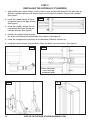
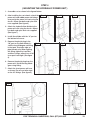
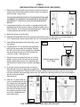
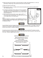
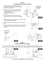
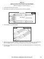
1
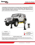
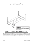
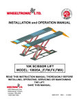
INSTRUCTION MANUAL MAX JAX SERIES Revision C 2-2012 pn# 199823 PLEASE READ THE ENTIRE CONTENTS OF THIS MANUAL PRIOR TO INSTALLATION AND OPERATION. BY PROCEEDING, YOU AGREE THAT YOU FULLY UNDERSTAND AND COMPREHEND THE FULL CONTENTS OF THIS MANUAL. DELIVER THIS MANUAL TO THE OWNER / USER / EMPLOYER WITH ALL OTHER INSTRUCTIONAL MATERIAL SUPPLIED WITH THE LIFT. FAILURE TO OPERATE THIS EQUIPMENT AS DIRECTED MAY CAUSE INJURY OR DEATH. IMPORTANT! CAUTION Reference ANSI/ALI ALIOM, safety requirements for installation and service of automotive lifts before installing lift. The safe operating temperature range for this product is 41º F. - 104º F. SHIPPING DAMAGE CLAIMS When this equipment is shipped, title passes to the purchaser upon receipt from the carrier. Consequently, claims for the material damaged in shipment must be made by the purchaser against the transportation company at the time shipment is received. PO BOX 178, MOORPARK, CA 93021 | 877-432-6627 | WWW.DANNMAR.COM TABLE OF CONTENTS IMPORTANT NOTICE...................................................................................................3 DEFINITIONS OF HAZARD LEVELS ........................................................................3 IMPORTANT SAFETY INSTRUCTIONS........................................................................4 OWNER / EMPLOYER RESPONSIBILITIES ..............................................................6 PARTS INVENTORY ...................................................................................................8 MAX JAX PARTS LIST ..........................................................................................9 MAX JAX ASSEMBLY DIAGRAM...............................................................................10 INSTALLATION INSTRUCTIONS ...............................................................................11 SELECTING SITE .................................................................................................11 FLOOR REQUIREMENTS ........................................................................................11 INSTALLING THE HYDRAULIC CYLINDERS............................................................12 MOUNTING THE HYDRAULIC POWER UNIT ...................................................13 SITE LAYOUT ...........................................................................................................14 INSTALLATION OF POWER DROP ANCHORS CONNECTING HYDRAULIC LINES INSTALLING THE LIFT ARMS ...................................................15 ......................................................................17 ...............................................................................17 HYDRAULIC POWER UNIT SET UP ......................................................................18 LIFT START UP / FINAL ADJUSTMENTS ............................................................18 BLEEDING....................................................................................................................19 POST INSTALLATION CHECK OFF OPERATION ......................................................................19 ...........................................................................................................20 SAFE LIFT OPERATION ........................................................................................22 INSTALLATION OF MOTORCYCLE ADAPTERS* ...................................................25 TROUBLESHOOTING GUIDE ...............................................................................26 WARRANTY INFORMATION ...............................................................................29 MAINTENANCE RECORDS...................................................................................30-31 *Optional equipment 2 VISIT US ON THE WEB AT WWW.DANNMAR.COM IMPORTANT NOTICE 1. Read this manual thoroughly before installing, operating, or maintaining this lift. 2. This lift is designed for indoor use only, and should not be installed in a pit or depression. 3. The floor on which the lift is to be installed must be 4-¼” inch minimum thickness concrete, with a minimum compressive strength of 3000 psi, and reinforced with steel bar. 4. The lifts have specific electrical requirements as described in the Installation Instructions section of this manual. 5. This lift has a minimum ceiling height requirement as described in the Installation Instructions section of this manual. 6. Failure by the owner to provide the recommended shelter, mounting surface, electrical supply, and ceiling height could result in unsatisfactory lift performance, property damage, or personal injury. 7. Do not attempt to install this lift if you have never been trained on basic automotive lift installation procedures. Reference ANSI/ALI ALIOM Safety requirements for Installation and Service of Automotive Lifts. 8. Never attempt to lift components without proper lifting tools such as forklift or cranes. Stay clear of any moving parts that can fall and cause injury. These instructions must be followed to insure proper installation and operation of your lift. Failure to comply with these instructions can result in serious bodily harm and void product warranty. 9. Dannmar Equipment will assume no liability for loss or damage of any kind, expressed or implied resulting from improper installation or use of this product. DEFINITIONS OF HAZARD LEVELS Identify the hazard levels used in this manual with the following definitions and signal words: Watch for this symbol: It Means: Immediate hazards which will result in severe personal injury or death. DANGER Watch for this symbol: It Means: Hazards or unsafe practices which could result in severe personal injury or death. WARNING Watch for this symbol: It Means: Hazards or unsafe practices which may result in minor personal injury, product or property damage. CAUTION Lubricate all cable sheaves, bearings, and shafts with grease prior to operating the lift. Lubricate all on an annual basis. Motors and all electrical components are not sealed against the weather and moisture. Install this lift in a protected indoor location. Failure by the owner to provide the recommended shelter could result in unsatisfactory lift performance, property damage, or personal injury. FOR TECHNICAL QUESTIONS, CALL (877)432-6627 3 IMPORTANT SAFETY INSTRUCTIONS READ THESE SAFETY INSTRUCTIONS ENTIRELY! IMPORTANT NOTICE ! Do not attempt to install this lift if you have never been trained on basic automotive lift installation procedures. Never attempt to lift components without proper lifting tools such as forklift or cranes stay clear of any moving parts that can fall and cause injury. 1. READ ALL INSTRUCTIONS. 2. READ AND UNDERSTAND all safety warning procedures before operating lift. 3. KEEP AREA WELL LIGHTED 4. WARNING! RISK OF EXPLOSION. This equipment has internal arcing or sparking parts which should not be exposed to flammable vapors. This machine should not be located in a recessed area or below floor level. 5. KEEP CONTROL HANDLES AND / OR BUTTONS dry, clean and free from grease and oil. 6. CARE MUST BE TAKEN as burns can occur from touching hot parts. 7. DO NOT operate equipment with a damaged power cord or if the equipment has been dropped or damaged until it has been examined by a qualified service person. 8. DO NOT let the power cord come in contact with hot manifolds or moving fan blades. 9. IF AN EXTENSION CORD IS NECESSARY, a cord with a current rating equal to or more than that of the equipment should be used. Cords rated for less current than the equipment may overheat. Care should be taken to arrange the cord so that it will not be tripped over or pulled. 10.ALWAYS UNPLUG EQUIPMENT FROM ELECTRICAL OUTLET WHEN NOT IN USE. Never use the power cord to pull the power plug from the outlet. Grasp the plug and pull to disconnect. 11.LET EQUIPMENT COOL COMPLETELY BEFORE PUTTING AWAY. Loop power cord loosely around equipment when storing. 12.TO REDUCE THE RISK OF FIRE, do not operate equipment in the vicinity of open containers of flammable liquids (i.e., gasoline). 13.ADEQUATE VENTILATION SHOULD BE PROVIDED when working on operating internal combustion engines. 14.KEEP HAIR, LOOSE CLOTHING, FINGERS, AND ALL PARTS OF THE BODY AWAY FROM MOVING PARTS. 15.TO REDUCE THE RISK OF ELECTRIC SHOCK, do not use on wet surfaces or expose to rain. 16.USE ONLY AS DESCRIBED IN THIS MANUAL. Use only manufacturer’s recommended attachments. 17.DO NOT raise vehicle on the lift until installation is completed as instructed in this manual. 18.KEEP HANDS AND FEET CLEAR. Remove hands and feet from any moving parts. Keep feet clear of lift when lowering. Avoid pinch points. 19.KEEP WORK AREA CLEAN. Cluttered work areas invite injuries. 20.CONSIDER WORK AREA ENVIRONMENT. Do not expose equipment to rain. DO NOT use in damp or wet locations. Keep area well lighted. 4 VISIT US ON THE WEB AT WWW.DANNMAR.COM 1. ONLY TRAINED OPERATORS should operate this lift. All non trained personnel should be kept away from work area. Never let non trained personnel come in contact with, or operate lift. 2. USE LIFT CORRECTLY. Use lift in the proper manner. Never use lifting adapters other than what is approved by the manufacturer. 3. DO NOT override self closing lift controls. 4. REMAIN CLEAR of lift when raising or lowering vehicle. 5. CLEAR AREA if vehicle is on danger of falling. 6. ALWAYS ENSURE that the safeties are engaged before any attempt is made to work on or near vehicle. 7. DRESS PROPERLY. Non skid steel toe footwear is recommended when operating lift. 8. GUARD AGAINST ELECTRIC SHOCK. This lift must be grounded while in use to protect the operator from electric shock. Never connect the green power cord wire to a live terminal. This is for ground only. 9. DANGER ! The power unit used on this lift contains high voltage. Disconnect power at the receptacle before performing any electrical repairs. Secure plug so that it cannot be accidentally plugged in during service. 10.ALWAYS WEAR SAFETY GLASSES. Everyday eyeglasses only have impact resistant lenses. They are not safey glasses. 11.MAINTAIN WITH CARE. Keep lift clean for better and safe performance. Follow manual for proper lubrication and maintenance instructions. Keep control handles and / or buttons dry, clean and free from grease and oil. 12.STAY ALERT. Watch what you are doing. Use common sense. Be aware ! 13.CHECK FOR DAMAGED PARTS. Check for alignment of moving parts, breakage of parts or any condition that may affect its operation. Do not use lift if any component is broken or damaged. 14.NEVER remove safety related components from the lift. Do not use lift if safety related components are damaged or missing. 15.NOTE: If attachments, accessories, or configuration modifying components that are located in the load path, affect operation of the lift, affect the lift electrical listing or affect intended vehicle accommodation are used on this lift and, if they are not certified for use on this lift, then the certification of this lift shall become null and void. Contact Dannmar Equipment for information pertaining to certified attachments, accessories, or configuration modifying components. FOR TECHNICAL QUESTIONS, CALL (877)432-6627 5 SAVE THESE INSTRUCTIONS OWNER / EMPLOYER RESPONSIBILITIES • Shall ensure that lift operators are qualified and that they are trained in the safe use and operation of the lift using the manufacturer’s operating instructions; ALI/SM01-1, ALI Lifting it Right safety manual; ALI/ST-90 ALI Safety Tips card; ANSI/ALI ALOIM-2000, American National Standard for Automotive Lifts Safety Requirements for Operation, Inspection and Maintenance; ALI/WL Series, ALI Uniform Warning Label Decals/Placards; and in the case of frame engaging lifts, ALI/LP-GUIDE, Vehicle Lifting Points/ Quick Reference Guide for Frame Engaging Lifts. • Shall establish procedures to periodically inspect the lift in accordance with the lift manufacturer’s instructions or ANSI/ALI ALOIM-2000, American National Standard for Automotive Lifts Safety Requirements for Operation, Inspection and Maintenance; and The Employer Shall ensure that lift inspectors are qualified and that they are adequately trained in the inspection of the lift. • Shall establish procedures to periodically maintain the lift in accordance with the lift manufacturer’s instructions or ANSI/ALI ALOIM-2000, American National Standard for Automotive Lifts Safety Requirements for Operation, Inspection and Maintenance; and The Employer Shall ensure that lift maintenance personnel are qualified and that they are adequately trained in the maintenance of the lift. • Shall maintain the periodic inspection and maintenance records recommended by the manufacturer or ANSI/ALI ALOIM-2000, American National Standard for Automotive Lifts Safety Requirements for Operation, Inspection and Maintenance. • Shall display the lift manufacturer’s operating instructions; ALI/SM 93-1, ALI Lifting it Right safety manual; ALI/ST-90 ALI Safety Tips card; ANSI/ALI ALOIM-2000, American National Standard for Automotive Lifts Safety Requirements for Operation, Inspection and Maintenance; and in the case of frame engaging lifts, ALI/LP-GUIDE, Vehicle Lifting Points/Quick Reference Guide for Frame Engaging Lifts; in a conspicuous location in the lift area convenient to the operator. • Shall not modify the lift in any manner without the prior written consent of the manufacturer. • Shall provide necessary lockout / tagout means for energy sources per ANSI Z244.1-1982 (R1993), safety requirements for the lockout / tagout of energy sources, before beginning any lift repairs. INSTALLER / OPERATOR PLEASE READ AND FULLY UNDERSTAND. BY PROCEEDING YOU AGREE TO THE FOLLOWING. • I have visually inspected the site where the lift is to be installed and verified the concrete to be in good condition and free of cracks or other defects. I understand that installing a lift on cracked or defective concrete could cause lift failure resulting in personal injury or death. • I understand that a level floor is required for proper installation and level lifting. • I understand that I am responsible if my floor is of questionable slope and that I will be responsible for all charges related to pouring a new level concrete slab if required and any charges. • I understand that Dannmar lifts are supplied with concrete fasteners meeting the criteria of the American National Standard “Automotive Lifts Safety Requirements for Construction, Testing, and Validation” ANSI/ALI • ALCTV-2006, and that I will be responsible for all charges related to any special regional structural and/or seismic anchoring requirements specified by any other agencies and / or codes such as the Uniform Building Code (UBC) and / or International Building Code (IBC). 6 VISIT US ON THE WEB AT WWW.DANNMAR.COM • I will assume full responsibility for the concrete floor and condition thereof, now or later, where the above equipment model(s) are to be installed. Failure to follow danger, warning, and caution instructions may lead to serious personal injury or death to operator or bystander or damage to property. • I understand that Dannmar lifts are designed to be installed in indoor locations only. Failure to follow installation instructions may lead to serious personal injury or death to operator or bystander or damage to property or lift. INSTALLER / OPERATOR PROTECTIVE EQUIPMENT Personal protective equipment helps makes installation and operation safer, however, it does not take the place of safe operating practices. Always wear durable work clothing during any installation and / or service activity. Shop aprons or shop coats may also be worn, however loose fitting clothing should be avoided. Tight fitting leather gloves are recommended to protect technician hands when handling parts. Sturdy leather work shoes with steel toes and oil resistant soles should be used by all service personnel to help prevent injury during typical installation and operation activities. Eye protection is essential during installation and operation activities. Safety glasses with side shields, goggles, or face shields are acceptable. Back belts provide support during lifting activities and are also helpful in providing worker protection. Consideration should also be given to the use of hearing protection if service activity is performed in an enclosed area, or if noise levels are high. FOR TECHNICAL QUESTIONS, CALL (877)432-6627 7 DANGER When removing the lift from shipping angles pay close attention as the posts can slide and can cause injury. Prior to removing the bolts make sure the posts are held securely by a fork lift or some other heavy lifting devise. PARTS INVENTORY Be sure to take a complete inventory of parts prior to beginning installation. 8 PART # 17200017 17202012 17207011 N/A 17206015 17206014 17156002 17156001 17206020 17206018 17206019 17206017 17206016 17200029 17200005 17200029 17201010 17207033 17207038 17207040 17200021 17201017 17207015 17158007 17207012 17158010 QTY 10 10 10 1 2 2 1 2 2 2 2 1 1 4 4 4 12 12 4 4 4 4 1 2 2 4 17157003 17207037 17107006 17108041 17157002 17157001 2 1 4 4 4 2 17157007 1 PARTS BAG DESCRIPTION 5/8” x 2” Hex Bolt For Anchors 5/8” Flat Washers 5/8” x 11 Power Drop Recess Anchors 5/8-11 X 4” Anchor Set Bolt Male Quick-Disconnect Fitting Female Quick-Disconnect Fitting Max Jax Hydraulic Hose Assembly Ø10 X 280mm Max Jax Hydraulic Hose Assembly Ø10 X 4520mm Pipe Reducer (3/8” Npt Female - 1/4” Npt Male) 3/8” x 3/8” Pipe Nipple 45-Degree Pipe Fitting (3/8” Npt Female - 3/8” Npt Male) Long 3/8” NPT - 3/8” JIC 90-Degree Fitting Long 90-Degree 3/8” x 3/8” O-Ring Fitting M8 X 1.25mm Hex Bolt ( Power Unit Bolts ) M8 X 25mm Hex Bolts (For Flow Divider) Hex Head Bolt M8 X 55Mm (For Column Wheels) M8 Nylon Hex Nuts 25mm C-Washers / Floor Mounting Shims “C” Retainer Clips for Arms Pull Rings for Arm Pins M10 X 45 Hex Head Bolt (For Column Top Straps) M10 Nylon Lock Nut (For Column Top Straps) Rubber Power Unit Dampener Pad 127mm Wheels For Power Unit Cart Retainers for Power Unit Cart Wheels 75mm Wheels For Columns PARTS BOX Column Top Straps Flow Divider Contact Lift Pads Stackable Pad Adapters Arm Pins Lock Bars OPTIONAL MOTORCYCLE ADAPTER KIT Adapter Frame Assembly VISIT US ON THE WEB AT WWW.DANNMAR.COM RECEIVED MAX JAX PARTS LIST ITEM NO 1 2 3 4 5 6 7 8 9 10 11 12 13 14 15 16 17 18 ITEM NO 1 2 3 4 5 6 7 8 9 10 11 12 13 14 15 16 17 18 19 20 PART NUMBER 17150002 17154001 17200028 17201010 17206016 17206017 17156001 17156002 17300003 17207037 17108041 17207015 17200005 17207011 17200017 17202012 17207033 17107006 PART NUMBER 17151001 17157001 17152001 17157002 17158009 17102009 17153001 17250017 17200029 17200021 17201010 17201017 17207038 17158010 17200022 17206015 17206019 17206018 17206020 17157003 MAX JAX ASSEMBLY DESCRIPTION MAX JAX POST ASSEMBLY MAX JAX POWER UNIT STAND ASSEMBLY M8 x 20 HEX HEAD BOLT M8 NYLON LOCK NUT MJ-MAORB 90~ LONG 6801-LL-06-06-NWO MALE 90° ELBOW, EXTRA LONG 2501-LL-06-06 MAX JAX HYD. HOSE ASSEMBLY Ø10 x 4520mm MAX JAX HYDRAULIC HOSE ASSEMBLY Ø10 x 295mm 110 VOLT, 1HP POWER UNIT HYDRAULIC FLOW DIVIDER SHORT LIFT PAD EXTENSION POWER UNIT VIBRATION DAMPENER M8 x 25 HEX HEAD BOLT 7/8 x 3-13/16 DROP IN SLEEVE ANCHOR 5/8-11 HEX HEAD BOLT 5/8 FLAT WASHER SHIM SLIP ON LIFT PAD ASSEMBLY MAX JAX POST ASSEMBLY DESCRIPTION MAX JAX POST WELDMENT MAX JAX SAFETY PIN ASSEMBLY MAX JAX LIFT HEAD WELDMENT MAX JAX LIFT HEAD PIN WELDMENT MAX JAX SLIDE BLOCK ARM LOCK ASSEMBLY MAX JAX ARM WELDMENT CYLINDER ASSEMBLY Ø2.0 x 42 HEX HEAD BOLT M8 x 55mm M10 x 45 HEX HEAD BOLT M8 NYLON LOCK NUT M10 NYLON LOCK NUT C RING Ø38mm OD 5103-150 MAX JAX WHEEL SERRATED HEX FLANGE SCREW M8 x 12 3/8-18 NPT MALE QUICK DISCONNECT COUPLING 45° STREET ELBOW 5503-06-06 HEX NIPPLE 5404-06-06 STRAIGHT EXPANDER 5405-04-06 MAX JAX POST STRAP WELDMENT FOR TECHNICAL QUESTIONS, CALL (877)432-6627 QTY 2 1 4 8 1 1 2 1 1 1 4 1 4 10 10 10 20 4 QTY 1 1 1 2 4 2 2 1 2 2 2 2 2 2 8 1 1 1 1 1 9 MAX JAX ASSEMBLY DIAGRAM 10 VISIT US ON THE WEB AT WWW.DANNMAR.COM INSTALLATION INSTRUCTIONS TOOLS REQUIRED Rotary Hammer Drill Or Similar (If Anchoring) 5/8” Masonry Bit 7/8” Masonry Bit Hammer 4 Foot Level Open End Wrench Set: Metric Socket And Ratchet Set: Metric Hex Key / Metric Allen Wrench Set Large Crescent Wrench Large Phillips Screwdriver Chalk Line Medium Flat Screwdriver Tape Measure : 25 Foot Minimum IMPORTANT NOTICE! These instructions must be followed to ensure proper installation and operation of your lift. Failure to comply with these instructions can result in serious bodily harm and void product warranty. Manufacturer will assume no liability for loss or damage of any kind, expressed or implied resulting from improper installation or use of this product. STEP 1 ( SELECTING SITE ) BEFORE INSTALLING YOUR NEW LIFT, CHECK THE FOLLOWING: 1. LIFT LOCATION: Always use architects plans when available. Check layout dimension against floor plan requirements making sure that adequate space is available. 2. OVERHEAD OBSTRUCTIONS: The area where the lift will be located should be free of overhead obstructions such as heaters, building supports, electrical lines etc. 3. DEFECTIVE FLOOR: Visually inspect the site where the lift is to be installed and check for cracked or defective concrete. CAUTION 4. OPERATING TEMPERATURE. Operate lift only between temperatures of 41° -104° F. 5. Lift is designed for INDOOR INSTALLATION ONLY. STEP 2 (FLOOR REQUIREMENTS) This lift must be installed on a solid level concrete floor with no more than 3 degrees of slope. Failure to do so could cause personal injury or death. DANGER DO NOT install this lift on any asphalt surface or any surface other than concrete. DO NOT install this lift on expansion seams or on cracked or defective concrete. DO NOT install this lift on a second / elevated floor without first consulting building architect. DO NOT install this lift outdoors. FOR TECHNICAL QUESTIONS, CALL (877)432-6627 11 STEP 3 ( INSTALLING THE HYDRAULIC CYLINDERS ) 1. After installing the column wheels, turn the columns over and lay them down with the open side up. Slide the carriages upwards until they are almost to the top of the columns. Remove the cylinders. (See figure 1) Fig. 1 2. Install the cylinder fittings as shown using teflon tape on the pipe threads. (See figure 2) 3. Install the cylinders through the carriage bottom plate then through the carriage top plate. (See figure 3) 4. Position the cylinder fittings through the access hole located on the backside of the columns. (See figure 4) 5. Lower the carriage until it rests firmly on the baseplate. Stand the columns up. 6. Install the column tie bars using the M10 x 45mm hex bolts, nuts and washers. (See figure 5) Fig. 2 Fig. 3 Shown with breakout to show top and bottom plate Fig. 4 12 Fig. 5 VISIT US ON THE WEB AT WWW.DANNMAR.COM STEP 4 ( MOUNTING THE HYDRAULIC POWER UNIT ) 1. Assemble cart as shown in the figured below: 2. After installing the cart wheels, attach the power unit and rubber power unit dampener pad to the power unit cart using the four 8 x 25mm hex bolts and nylon lock nuts supplied. (See figure 6) Step 1 Step 2 Step 3 3. Attach the hydraulic flow divider to the power unit cart using the four 8 x 20mm hex bolts and nylon lock nuts supplied. (See figure 7) 4. Install flow divider with the “in” port on the bottom left corner. 5. Remove the plastic plug in the “IN” port on the flow divider. InFig. 6 stall the long 90 degree npt fitting in that port. Use teflon tape on pipe threads only. When tighting the fitting, tighten by hand first and then using a wrench turn 3 full turns past hand tight. (See figure 8) Fig. 7 6. Remove the plastic plug from the power unit. Install the long 90 degree o-ring fitting. 7. Attach the short power unit hose as shown. Do not use teflon tape on the JIC fittings. (See figure 9) Fig. 8 Fig. 9 FOR TECHNICAL QUESTIONS, CALL (877)432-6627 13 STEP 5 ( SITE LAYOUT ) 1. Based on the vehicles you will be servicing and the size of the shop space determine the desired width and location of the lift. 2. Once a location is determined, use a carpenters chalk line to layout a grid for the post locations. Keep all dimensions and squareness within 1/8” or malfunctioning of the lift can occur. 3. After the post locations are properly marked, use a chalk or crayon to make an outline of the columns on the floor at each location using the post base plates as a template. 4. Double check all dimensions and make sure that the layout is perfectly square. Note: Wide or narrow installation is possible. The lift can be installed at a width that suits the vehicles you will be raising. You may even choose to install additional anchors at varied column positions for adaptability to multiple vehicle configurations. Sport compacts 105” - 115” Typical Mid size 110” - 120” Typical Light duty / sport trucks 115” - 120” Typical Full size trucks 120” - 130” Typical Use the edge of the base plate to line up the posts along the chalk line Chalk line 14 VISIT US ON THE WEB AT WWW.DANNMAR.COM STEP 6 ( INSTALLATION OF POWER DROP ANCHORS ) 1. Before proceeding, double check location and measurements, make certain that the base plates of each column are aligned with the chalk / crayon lines. Fig. 10 FOLLOW PROCEDURE EXACTLY FOR PROPER FITTING AND ALIGNMENT OF ANCHORS. THE HOLES MUST BE DRILLED ACCORDING TO THE HOLE LOCATION DIAGRAM SHOWN BELOW. 2. Using the base plate on the column as a guide, hold the drill perpendicular to the concrete surface and drill one pilot anchor hole at location “A” in the concrete approximately 2” deep using a rotary hammer drill and 5/8” concrete drill-bit. 3. Move the column out of the way. 4. Hold the drill perpendicular to the concrete surface drill out the “A” pilot hole to a minimum depth of 5-1/2” deep using a rotary hammer drill and 7/8” concrete drill-bit. (See figure 11) 5. After drilling, thoroughly clean hole using a vacuum cleaner. Fig. 11 6. Thread the 5/8” x 4” set tool hex bolt (sacrificial bolt) into the power drop anchor body. Position the 5/8 nut at a point on the threads that will allow the power-drop anchor to set 5/8” beneath the concrete surface. (See figure 12 ) 7. Tap anchor bolt assembly into hole “A”until the bottom surface of the nut reaches the concrete and the power drop anchor rests approximately 5/8” below the surface of the concrete. (See figure 13 ) Drill hole approximately 5-1/2” Deep. 8. To set the anchor, first remove the set tool hex bolt and add a washer to give better support during the setting procedure. Tighten the hex nut while holding the bolt head (to assure the anchor does not spin) and until the power drop anchor sets 1/8" below the concrete surface. Do not use an impact wrench for this procedure. (See figure 14 ) Fig. 13 Fig. 14 9. After the “A” power drop anchor is installed and set, move the column back into position, lining up the anchor holes and the base plate with the chalk line mark on the floor. Anchor the column to the floor using one of the standard anchor bolts and washer. Fig. 12 FOR TECHNICAL QUESTIONS, CALL (877)432-6627 15 10.With the column firmly anchored, use the base plate as a guide, then drill pilot holes b, c, d & e approximately 2” deep using a rotary hammer drill and 5/8” concrete drill-bit. 11.Move the column out of the way. 12.Repeat previous steps 5 - 9 making sure the column base plate remains perfectly positioned over each individual pilot hole. Fig. 15 13.If shimming is required, insert the shims as necessary under the base plate so that when the provided 5/8” x 2” anchor bolts are tightened, the columns will be plumb both side to side and front to rear. (See figure 15) 14.With the shims and anchor bolts in place, tighten all 5/8” x 2” anchor bolts tight to the base plate . Turn 3 to 3-3/4 turns. Do not use an impact wrench for this procedure. NOTE: IT WILL BE HELPFUL TO MARK ON OR OTHERWISE NOTE THE LOCATION OF SHIMS USED AT EACH DROP ANC TO ASSIST AT TIME OF REINSTALLATION. WARNING Inspect all drop in anchors for proper setting and or damage each time the lift is re-installed. Inspect the concrete for cracks defects and/or damage. Do not reinstall the lift if any of the drop in anchors are defective or the concrete is cracked or defective. WARNING It may be necessary to shim the columns to ensure that the columns are plumb. The columns must be plumb and square or damage or injury may occur when using the lift. Do not exceed 1/8’ total shim thickness when using the supplied Drop in anchors. WARNING IMPORTANT LEVELING INSTRUCTIONS Before operating your lift, check to make sure both “A” and “B” measurements are equal. The lift arms must be level before operation. If your lift arms are not level, shim the columns as required. A LEVEL B 16 VISIT US ON THE WEB AT WWW.DANNMAR.COM STEP 7 ( CONNECTING HYDRAULIC LINES ) 1. Thread the male quick disconnect fittings onto the rear cylinder fittings using teflon tape on the pipe threads. (See figure 16) Male Quick Disconnect Fitting 2. Thread one end of the male npt hose fitting into one of the top ports of the flow divider. Turn until 80ft-lbs of torque. Do this with both hoses. (See figure 17) 3. Install the female quick-disconnect fittings at each of the other male npt hose ends. (See figure 18) Fig. 16 4. Recheck all fitting connections to make sure they are properly tightened before proceeding. 5. Position the power unit stand at the front or rear of the vehicle. 6. Connect the free end of each cylinder hose assembly to the quick disconnect fitting at the base of each cylinder. (See figure 19) Fig. 17 Female Quick Disconnect Fitting Fig. 18 Fig. 19 STEP 8 ( INSTALLING THE LIFT ARMS ) 1. Place the Lift Arm Assembly on the Lift Heads. Install the Lift Head Pins into the Lift Head and through the holes in the Arm Assembly then press the external c-clip into place on the arm pin. (See figure 20 / 21 ) Fig. 20 Fig. 21 C-Clip FOR TECHNICAL QUESTIONS, CALL (877)432-6627 17 STEP 9 ( HYDRAULIC POWER UNIT SET UP ) 1. Fill the power unit reservoir with 7 quarts of 10 weight hydraulic oil or dexron III automatic transmission fluid. Make sure the funnel used to fill the power unit is clean. An additional 1.5 Quarts should be added after initial bleeding, at 1/3 or 1/2 full lift height. Do not add additional quarts when lift is lifted to full height. 2. The standard power unit for your lift is 110/220 volt, 50/60hz, single phase. The lift should be plugged into a dedicated circuit with a 30 amp circuit breaker. WARNING All wiring must be performed by a certified electrician only. SEE WIRING INSTRUCTIONS AFFIXED TO MOTOR FOR PROPER WIRING INSTRUCTIONS. DANGER RISK OF EXPLOSION! This equipment has internal arcing or parts that may spark and should not be exposed to flammable vapors. The motor should not be located in a recessed area or below floor level. IMPORTANT • DO NOT run power unit with no oil. Damage to pump can occur. • The power unit must be kept dry. Damage to power unit caused by water or other liquids such as detergents, acid etc. , is not covered under warranty. • Improper electrical hookup can damage the motor and will not be covered under warranty. • Motor can not run on 50HZ without a physical change in the motor. • Use a separate breaker for each power unit. • Protect each circuit with a time delay fuse or circuit breaker. • For 110-120 volt, single phase, use a 30 amp breaker. • For 208 -230 volt, single phase, use a 25 amp breaker. • For 208-230 volt, three phase, use a 20 amp breaker. • For 380-440 volt, three phase, use a 15 amp breaker. STEP 10 ( LIFT START UP / FINAL ADJUSTMENTS ) During the START-UP procedure, observe all operating components and check for proper installation and adjustment. DO NOT attempt to raise vehicle until a thorough operational check has been completed. 1. Spray the inside of the columns where the slide blocks glide with a white lithium grease or equivalent 2. Remove both safety lock bars from the columns. 3. Test the power unit by pressing the push-button switch. If the motor sounds like it is operating properly, raise the lift a few inches and check all hose connections for leaks. If the motor gets hot or sounds peculiar, stop and check all electrical connections. 4. Continue pressing the raise button until the lift starts to move. 18 VISIT US ON THE WEB AT WWW.DANNMAR.COM WARNING • KEEP HANDS AND FEET CLEAR of lift when operating. • Avoid pinch points. 5. Raise the lift half way until the lift arms are approximately 24” off the floor. 6. Loosen the bolts on the Arm Restraints. Adjust the Arm Restraints so the gears mesh firmly and smoothly. Tighten the Arm Restraint Bolts. Apply a small amount of grease to the gears. (See figure 22) STEP 11 ( BLEEDING ) Fig. 22 1. With the lift in an elevated position, the hoses connected and the oil reservoir full, loosen the bleeder screws located at the top of each hydraulic cylinder using a allen wrench. Do not completely remove the bleeder screws. Watch and listen as trapped air escapes the cylinders and fluid beings to weep from the screw area. Once steady fluid appears, re-tighten the bleeder screw. (See figure 23) Bleeder Screw DANGER The lift will move down when bleeding make sure all equipment, personnel, hands and feet are clear before bleeding . 2. Press the power unit raise button until both cylinders reach their full stroke. Do not continue pressing the raise button after lift reaches full height damage to the motor and / or flow divider can occur if continued. Fig. 23 3. Repeat the bleeding procedure. 4. Press the lowering handle inwards until the lift lowers completely to the floor. Repeat the above procedure until the lift maintains level lifting and lowering. WARNING DO NOT use lift if an unlevel lifting condition occurs at the arm pad locations that is greater than 3-degrees or 1.5”. If an unbalanced condition occurs, Follow the bleeding instructions shown on this page or consult factory. The lift must be re-leveled, shimmed and bled each time the lift is reinstalled. Failure to follow these instructions can result in serious injury or death. POST INSTALLATION CHECK OFF Columns are properly shimmed and stable Anchor bolts are tightened Pivot / sheave pins are properly attached Electric power supply confirmed Tie bar straps installed and bolts tight Safety locks bars removed Check for hydraulic leaks Oil level Lubcation of critical components Check for overhead obstructions Lift arms are level Arm restraints properly adjusted All screws, bolts, and pins are secured Surrounng area is clean Operation, maintenance and safety manuals on site. FOR TECHNICAL QUESTIONS, CALL (877)432-6627 19 STEP 12 (OPERATION) To raise lift; 1. Load the vehicle onto the lift using vehicle lifting guide to determine proper lifting points. 2. Never use lift pad assemblies without rubber slip over pads in place. 3. Set the parking brake or use a wheel chock to hold the vehicle in position. 4. Before raising vehicle, be sure all personnel are clear of the lift and surrounding area. Pay careful attention to overhead clearances. 5. Raise the lift to the desired height by pressing the push button on the power unit. Fig. 24 6. After the vehicle is raised to the desired height, pass the safety lock bars through each column then lower lift onto the lock bars. Always insure safety lock bars are installed before entering work area. (See figure 24) To lower lift; 1. Before lowering vehicle, be sure all personnel are clear of the lift and surrounding area. Pay careful attention to overhead clearances. Insure all tools and equipment have been cleared from under the lift. 2. Raise the lift off of the safety lock bars by pressing the push button on the power unit. Make sure you raise the lift by at least one inch to allow adequate clearance for the safety bars to be removed. Remove lock bars. 3. Push the lowering handle on the power unit until the lift has descended completely. WARNING When lowering the lift pay careful attention that all personnel and objects are kept clear. Always keep a visual line of site on the lift at all times. Always make sure that both lock bars are removed. WEEKLY MAINTENANCE 1. Lubricate all moving parts with a white lithium grease. 2. Check all connections, bolts and pins to insure proper mounting. MONTHLY MAINTENANCE 1. Make a visual inspection of all moving parts and check for excessive signs of wear. 2. Check condition of lift pads and adapters. 3. Check condition of arm restraints. Adjust as necessary. 4. Replace all faulty parts before lift is put back into operation. 20 VISIT US ON THE WEB AT WWW.DANNMAR.COM TO RAISE LIFT • • • • • • • • • • • • • • Always follow the bleeding instructions outlined in the manual prior to using your lift. Read operating and safety manuals before using lift. Always lift vehicle according to manufacturer’s recommended lifting points. Position vehicle between columns. Adjust swing arms so that vehicle is positioned with the center of gravity midway between pads. Position lift contact pads at manufacturers recommended lifting points. Use truck adapters as needed. Never exceed 6” of pad / adapter height. Raise lift by pressing raise button on power unit until contact pads make contact with the underside of vehicle. Recheck to make sure vehicle is secure. Raise vehicle to desired working height then press power unit Lowering handle until lift carriages rest onto nearest safety lock position. Maintain visual contact with vehicle and surrounding area at all times while raising lift. Stop immediately if load shifts or becomes unlevel. Always ensure safety lock bar(s) are installed before any attempt is made to work on or near vehicle. Always ensure contact pads are making full contact with vehicle before attempting to work on or near vehicle. TO LOWER LIFT • Raise lift by pressing raise button on power unit. Elevate lift at least one inch to allow adequate clearance to remove lock bar(s). • Remove both safety lock bar(s). • Be sure tool trays, stands or personnel are removed from under vehicle. • Lower vehicle by pressing power unit lowering handle until lift has descended completely . • Maintain visual contact with vehicle and surrounding area at all times while lowering lift. • Stop immediately if load shifts or becomes unlevel. • Before removing vehicle from lift area, position lift arms to provide unobstructed exit. • Never, drive over lift arms. REQUIRED MONTHLY MAINTENANCE • • • • • • • Always consult operation manual for factory recommended maintenance. Check arm restraints for proper operation. Check all bolts and pins to ensure proper mounting. Visually inspect safety lock bar(s). Visually inspect concrete floor. Do not use lift if concrete foundation shows signs of deterioration. Inspect all anchor bolts. Inspect all lift pads, replace if necessary. WARNING • Do not use lift if an unlevel lifting condition occurs at the arm pad locations that is greater than 3-degrees or 1.5”. • Warning: if anchor bolts are loose, or any component of the lift is found to be defective, do not use lift! • Install and inspect all quick connect/disconnect hose ends before any attempt is made to raise vehicle. • Securely tighten all anchor bolts prior to operation. • Never operate the lift with any person or equipment below. • Never exceed rated capacity. • Always ensure safety lock bar(s) are engaged before any attempt is made to work on or near vehicle. • Never leave lift in an elevated position unless the safety lock bar(s) are engaged. • Do not permit electric motor to get wet! Motor damage caused by dampness is not covered under warranty FOR TECHNICAL QUESTIONS, CALL (877)432-6627 21 SAFE LIFT OPERATION Automotive and truck lifts are critical to the operation and profitability of your business. The safe use of this and other lifts in your shop is critical in preventing employee injuries and dama lifts safely you can insure that your shop is profitable, productive and safe. Safe operation of automotive lifts requires that only trained employees should be allowed to use the lift. TRAINING SHOULD INCLUDE, BUT NOT LIMITED TO: • Proper positioning of the vehicle on the lift arms. (See manufacturers minimize wheel base loading requirements.) • Use of the operating controls and the lift capacity. • Proper use of jack stands or other load supporting devices. • Proper use, understanding and visual identification of safety lock devices and their operation. • Reviewing the safety rules. Proper housekeeping procedures (lift area should be free of grease, oil, tools, equipment, trash, and other debris). • A daily inspection of the lift should be completed prior to its use. Safety devices, operating controls, lift arms and other critical parts should be inspected prior to using the lift. • All maintenance and repairs of the lift should be completed by following repair parts should meet or exceed OEM specifications. Repairs should only be completed by a qualified lift technician. • The vehicle manufacturer’s recommendations should be used for spotting and lifting the vehicle. LIFT OPERATION / SAFETY • It is important that you know the load limit. Be careful that you do not overload the lift . If you are un- sure what the load limit is, check the data plate found on one of the lift columns or contact the manufacturer. The center of gravity should be followed closely to what the manufacturer recommends. • Always make sure you have proper overhead clearance. Additionally, check that attachments, ( vehicle signs, campers, antennas, etc.) are not in the way. Be sure that prior to the vehicle being raised, the doors, trunk, and hood are closed securely. • Prior to being raised, make sure there is no one standing closer than six feet from the lift. After positioning the vehicle on the lift runways, set the emergency brake, make sure the ignition is off, the doors are closed, overhead obstructions are cleared, and the transmission is in neutral. • Double check that the automatic chock devices are in position and then when the lift is raised, observe the chocks. • Put pads or adapters in the right position under the contact points that have been recommended. • The lift should be raised just until the vehicle’s wheels are about one foot off the ground. If contact with the vehicle is uneven or it appears that the vehicle is not sitting secure, carefully lower the lift and readjust. • Always consider potential problems that might cause a vehicle to slip, i.e., heavy cargo, undercoating, etc. • Pay attention when walking under a vehicle that is up on the hydraulic lift. 22 VISIT US ON THE WEB AT WWW.DANNMAR.COM DANGER • DO NOT leave the controls while the lift is still in motion. • DO NOT stand directly in front of the vehicle or in the bay when vehicle is being loaded or driven into position. • DO NOT go near vehicle or attempt to work on the vehicle when being raised or lowered. • REMAIN CLEAR of lift when raising or lowering vehicle. • DO NOT rock the vehicle while on the lift or remove any heavy component from vehicle that may cause excessive weight shift. • DO NOT lower the vehicle until people, materials, and tools are clear. • ALWAYS INSURE that the safeties are engaged and lowered on to the safety ladders before any attempt is made to work on or near vehicle. • Some vehicle maintenance and repair activities may cause the vehicle to shift. Follow the manufac- turer’s guidelines when performing these operations. The use of jack stands or alternate lift points may be required when completing some repairs. • READ AND UNDERSTAND all safety warning procedures before operating lift. • KEEP HANDS AND FEET CLEAR. Remove hands and feet from any moving parts. Keep feet clear of lift when lowering, and avoid pinch points. • ONLY TRAINED OPERATORS should operate this lift. All non trained personnel should be kept away from work area. • NEVER let non trained personnel come in contact with, or operate lift. • USE LIFT CORRECTLY. Use lift in the proper manner. Never use lifting adapters other than what is approved by the manufacturer. • DO NOT override self closing lift controls. • CLEAR AREA if vehicle is on danger of falling. • STAY ALERT. Watch what you are doing. Use common sense. Be aware. • CHECK FOR DAMAGED PARTS. Check for alignment of moving parts, breakage of parts or any condition that may affect its operation. Do not use lift if any component is broken or damaged. • NEVER remove safety related components from the lift. Do not use lift if safety related components are damaged or missing. • When the lift is being lowered, make sure everyone is standing at least six feet away. • Be sure there are no jacks, tools, equipment, left under the lift before lowering. • Always lower the vehicle down slowly and smoothly. FOR TECHNICAL QUESTIONS, CALL (877)432-6627 23 STEP 13 ( Lift Removal ) 1. Depress the lowering valve on the power unit. 2. Ensure that the lift is lowered all the way to the ground. 3. Disconnect the power unit from the power source and / or ensure that the power to the circuit is shut off to prevent accidental powering on of the lift while disassembling. 4. Disconnect the cylinder hoses from the cylinder. Hoses can be coiled and stored in the power unit cart. WARNING Before removing cylinder hoses, always ensure that the hydraulic pressure has been relieved from the system by depressing the lowering valve until the lift is fully lowered or the raised load is fully settled onto the safety lock bars. Never connect or disconnect hoses with the lift in an elevated non-locked position. DANGER Do not perform any maintenance or installation of any components with out first ensuring that electrical power has been disconnected at the source or panel and cannot be re-energized until all maintenance and / or installation procedures are completed. 5. Be careful to clean up any spilled hydraulic fluid that may drip from the hose assemblies. 6. Place the safety lock bars in the top column holes. 7. Remove the lift arm assemblies. 8. Loosen the anchor bolts . Be careful not to disturbed the lift column until ready to move the column. 9. Move the column to your storage area. Secure with straps or other device to prevent any accidental tipping or movement of the columns during storage. STEP 14 ( Re-Installation ) 1. Clear installation area of debris, tools and equipment. 2. Blow out the mounting holes with compressed air. 3. Inspect the drop in anchors for proper setting and the concrete for defects and / or damage. 4. Line up the holes of the Base Plates with the holes. Re-shim the lift as required to ensure the lift is installed level. 5. With the Shims and Anchor Bolts in place, tighten all Anchor Bolts tight to the base plate. Do not use an impact wrench for this procedure. 6. Follow all procedures as outlined in steps 8 - 12. WARNING Inspect all drop in anchors for proper setting and or damage each time the lift is re-installed. Inspect the concrete for cracks defects and / or damage. Do not reinstall the lift if any of the drop in anchors are defective or the concrete is cracked or defective. DANGER The lift must be re-leveled, shimmed and blead each time the lift is reinstalled. Failure to do so may result in Injury or death. 24 VISIT US ON THE WEB AT WWW.DANNMAR.COM STEP 15 ( INSTALLATION OF MOTORCYCLE ADAPTERS* ) *Motorcycle Adapter is an optional accessory. 1. Lower the lift all the way to the ground. 2. Swivel both arms towards the center line of the lift until they are parallel. Arms Parallel Fig. 25 Arms Extend 3. Fully extend both arms. (See figure 25) Fig. 26 Adapter Button 4. Align the motorcycle adapters and lower onto the lift arms. Ensure it rests firmly on top of the lift arms. Place the adapter buttons thru the motorcycle adapter into the lift arm hole’s (See figure 26) 5. Disconnect the cylinder hose from the flow control valve opposite the side you are using for the motorcycle adapter. FOR TECHNICAL QUESTIONS, CALL (877)432-6627 25 TROUBLESHOOTING GUIDE LIFT WILL NOT RAISE POSSIBLE CAUSE 1. Air in oil, (1,2,8,13) 2. Cylinder binding, (9) 3. Cylinder leaks internally, (9) 4. Motor run backward under pressure, (11) 5. Lowering valve leaks, (3,4,6,10,11) 6. Motor runs backwards, (7,14,11) 7. Pump damaged, (10,11) 8. Pump won’t prime, (1,8,13,14,3,12,10,11) 9. Relief valve leaks, (10,11) 10.Voltage to motor incorrect, (7,14,11) REMEDY INSTRUCTION 1. Check for proper oil level. The oil level should be up to the bleed screw in the reservoir with the lift all the way down. 2. Bleed cylinders. 3. Flush Release valve, hold release handle down and start unit for 15 seconds allowing possible contamination to break up. 4. Dirty oil, replace oil with clean 10 weight hydraulic fluid or Dextron III ATF. 5. Tighten fasteners to recommended torques settings. 6. Check for free movement of release. If handle does not move freely, replace bracket or handle assembly. 7. Check motor is wired correctly. Compare wiring of motor to electrical diagram on drawing. 8. Oil seal is damaged or cocked. Replace oil seal around pump shaft. 9. Consult Lift Manufacturer. 10.Replace with new part. 11.Return unit for repair. 12.Check pump mounting bolts. Bolts should be torqued to 15 - 18 ft. lbs. 13.Inlet screen clogged. Clean inlet screen or replace. 14.Check wall outlet voltages and wiring. Make sure unit and wall outlet are wired 26 VISIT US ON THE WEB AT WWW.DANNMAR.COM MOTOR WILL NOT RUN POSSIBLE CAUSE 1. Fuse blown, (5,2,1,3,4) 2. Limit switch burned out, (1,2,3,4) 3. Microswitch burned out, (1,2,3,4) 4. Motor burned out, (1,2,3,4,6) 5. Voltage to motor incorrect, (2,1,8) REMEDY INSTRUCTION 1. Check for correct voltage. Compare supply voltage with voltage on motor name tag. Check that the wire is sized correctly. N.E.C. table 310-12 requires AWG 10 for 30 Amps. 2. Check motor is wired correctly. Compare wiring of motor to electrical diagram on drawing. 3. Don’t use extension cords. According to N.E.C. : “ The size of the conductors should be such that the voltage drop would not exceed 3% to the farthest outlet for power”. 4. Replace with new part. 5. Reset circuit breaker / fuse. 6. Return unit for repair. 7. See Installation Manual. 8. Check wall outlet voltage and wiring. Make sure unit and wall outlet is wired properly. Motor must run at 110/120 VAC. LIFT LOWERS SLOWLY OR NOT AT ALL POSSIBLE CAUSE 1. Cylinders binding, (1) 2. Release valve clogged, (5,4,2,3) 3. Pressure fitting too long, (6) REMEDY INSTRUCTION 1. Consult Lift Manufacturer. 2. Replace with new part. 3. Return for repair. 4. Check oil. Use clean 10 weight hydraulic oil or Dexron III automatic transmission fluid only. If fluid is contaminated, replace with clean fluid and clean entire system. 5. Clean release valve. Wash release valve in solvent and blow out with air. 6. Replace fitting with short thread lead. FOR TECHNICAL QUESTIONS, CALL (877)432-6627 27 WILL NOT RAISE LOADED LIFT POSSIBLE CAUSE 1. Air in oil, (1,2,3,4) 2. Cylinder binding, (5) 3. Cylinder leaks internally, (5) 4. Lift overloaded, (6,5) 5. Lowering valve leaks, (7,8,1,5,9) 6. Motor runs backwards, (10,12,9) 7. Pump damaged, (5,9) 8. Pump won’t prime, (1,2,3,4,5,11,9) 9. Relief valve leaks, (8,5,9) 10.Voltage to motor incorrect, (10,12,5) REMEDY INSTRUCTION 1. Check oil level. The oil level should be up to the bleed screw in the reservoir with the lift all the way down. 2. Check / Tighten inlet tubes or Replace inlet hose assembly. 3. Oil seal is damaged or cocked. Replace oil seal around pump shaft. 4. Bleed cylinders. 5. Consult Lift Manufacturer. 6. Check vehicle weight. Compare weight of vehicle to weight limit of the lift. 7. Flush release valve. Hold release handle down and start unit allowing it to run for 15 seconds. 8. Replace with new part. 9. Return unit for repair. 10.Check if motor is wired correctly. Compare wiring of motor to electrical diagram on power unit drawing. 11.Inlet screen clogged. Clean inlet screen or replace. 12.Check wall outlet voltage and wiring. Make sure unit and wall outlet is wired properly. 28 VISIT US ON THE WEB AT WWW.DANNMAR.COM WARRANTY INFORMATION MAX JAX LIFT SYSTEM DELIVER THESE INSTRUCTIONS TO THE LIFT OWNER ! READ THIS ENTIRE MANUAL BEFORE INSTALLATION & OPERATION BEGINS. This instruction manual has been prepared especially for you. Your new lift is the product of over 25 years of continuous research, testing and development and is the most technically advanced lift on the market today. RECORD HERE THE FOLLOWING INFORMATION WHICH IS LOCATED ON THE SERIAL NUMBER DATA PLATE AND THE POWER UNIT DATA PLATE. YOU CAN ALSO RECORD THE FOLLOWING INFORMATION ONLINE AT HTTP://WWW.DANNMAR.COM/WARRANTY.ASP Lift Serial #: __________ Power Unit Serial #: __________ Lift Model #: __________ Power Unit Model #: __________ Lift Manufacturing Date: __________ Power Unit Manufacturing Date: __________ WARRANTY 1. DURATION: From the date of purchase by the original purchaser. Any Dannmar MaxJaxTMlift system: Two-Year warranty on the lift structure and other associated structural components; One-Year warranty on the power unit and hydraulic cylinders, and other assembly components such as valves, hoses, fittings etc. Against defects in material or workmanship under normal use and service, from the date of installation or from the date of shipment by Dannmar or a Dannmar distributor whichever comes first. 2. WHO GIVES THIS WARRANTY (WARRANTOR): Dannmar Inc., 646 Flinn Ave., Moorpark, CA 93021 3. WHO RECEIVES THIS WARRANTY (PURCHASER): The original purchaser (other than for purpose of resale). 4. WHAT PRODUCTS ARE COVERED BY THIS WARRANTY: Any Dannmar MaxJax lift system. 5. WHAT IS COVERED UNDER THIS WARRANTY: Manufacturer defects due to material and workmanship with the exceptions noted below. 6. WHAT IS NOT COVERED UNDER THIS WARRANTY: A. ANY INCIDENTAL, INDIRECT, OR CONSEQUENTIAL LOSS, DAMAGE, OR EXPENSE THAT MAY RESULT FROM ANY DEFECT, FAILURE, OR MALFUNCTION OF DANNMAR INC PRODUCT. B. Any failure that results from an accident, purchaser’s abuse, neglect or failure to operate products in accordance with instructions provided in the owner’s manual(s) supplied. C. Pre-delivery service, i.e. assembly, oil, etc. D. Items or service normally required to maintain the product: i.e. lubricants, rubber pads, hoses that become worn, other wear items, etc. E. Additional items not covered under this warranty: a. Any component damaged in shipment or any failure caused by installing or operating unit under conditions not in accordance with installation and operation guidelines or damaged by contact with tools or surroundings. b. Pump or valve failure caused by rain, excessive humidity, corrosive environments or other contaminants. c. Cosmetic defects that do not interfere with lift system functionality. d. Damage due to incorrect voltage or improper wiring. Other items not listed but considered general wear parts. a. hoses worn or kinked b. rubber lift contact pads 7. RESPONSIBILITIES OF WARRANTOR UNDER THIS WARRANTY: Repair or replace, at Warrantor’s option, lift or component which is defective, has malfunctioned and/or failed to conform within duration of the warranty period. Dannmar Inc. will pay reasonable labor costs for the first 12 months only on parts returned as previously described. 8. RESPONSIBILITIES OF PURCHASER UNDER THIS WARRANTY: A. Provide dated proof of purchase and maintenance records. B. Lift or components must be delivered or shipped to the nearest Dannmar Authorized Service Center. Freight costs, if any, must be borne by the purchaser. C. Use reasonable care in the operation and maintenance of the products as described in the owner’s manual(s). 9. WHEN WARRANTOR WILL PERFORM REPAIR OR REPLACEMENT UNDER THIS WARRANTY: Repair or replacement will be scheduled and serviced according to the normal work flow at the servicing location, and depending on the availability of replacement parts. THESE WARRANTIES DO NOT EXTEND TO ANY COSMETIC DEFECT NOT INTERFERING WITH EQUIPMENT FUNCTIONALITY OR ANY INCIDENTAL, INDIRECT, OR CONSEQUENTIAL LOSS, DAMAGE, OR EXPENSE THAT MAY RESULT FROM ANY DEFECT, FAILURE, OR MALFUNCTION OF A DANNMAR PRODUCT OR THE BREACH OR DELAY IN PERFORMANCE OF THE WARRANTY. This warranty is exclusive and in lieu of all other warranties expressed or implied. Dannmar makes no warranty on components and/or accessories fur-nished to Dannmar by third parties. These are warranted only to the extent of the original manufacturers warranty to Dannmar. Dannmar makes no warran-ty on other items not listed but may be considered general wear parts. Dannmar reserves the right to make design changes or add improvements to its prod-uct line without incurring any obligation to make such changes on product sold previously. Warranty adjustments within the above stated policies are based on the model and serial number of the equipment. This data must be furnished with all warranty Extended Warranty Available at http://www.dannmar.com/warranty.asp FOR TECHNICAL QUESTIONS, CALL (877)432-6627 29 MAINTENANCE RECORDS ___________________________________________________________________ ___________________________________________________________________ ___________________________________________________________________ ___________________________________________________________________ ___________________________________________________________________ ___________________________________________________________________ ___________________________________________________________________ ___________________________________________________________________ ___________________________________________________________________ ___________________________________________________________________ ___________________________________________________________________ ___________________________________________________________________ ___________________________________________________________________ ___________________________________________________________________ ___________________________________________________________________ ___________________________________________________________________ ___________________________________________________________________ ___________________________________________________________________ ___________________________________________________________________ ___________________________________________________________________ ___________________________________________________________________ ___________________________________________________________________ ___________________________________________________________________ ___________________________________________________________________ ___________________________________________________________________ ___________________________________________________________________ ___________________________________________________________________ ___________________________________________________________________ ___________________________________________________________________ ___________________________________________________________________ ___________________________________________________________________ ___________________________________________________________________ ___________________________________________________________________ ___________________________________________________________________ ___________________________________________________________________ ___________________________________________________________________ 30 VISIT US ON THE WEB AT WWW.DANNMAR.COM MAINTENANCE RECORDS ___________________________________________________________________ ___________________________________________________________________ ___________________________________________________________________ ___________________________________________________________________ ___________________________________________________________________ ___________________________________________________________________ ___________________________________________________________________ ___________________________________________________________________ ___________________________________________________________________ ___________________________________________________________________ ___________________________________________________________________ ___________________________________________________________________ ___________________________________________________________________ ___________________________________________________________________ ___________________________________________________________________ ___________________________________________________________________ ___________________________________________________________________ ___________________________________________________________________ ___________________________________________________________________ ___________________________________________________________________ ___________________________________________________________________ ___________________________________________________________________ ___________________________________________________________________ ___________________________________________________________________ ___________________________________________________________________ ___________________________________________________________________ ___________________________________________________________________ ___________________________________________________________________ ___________________________________________________________________ ___________________________________________________________________ ___________________________________________________________________ ___________________________________________________________________ ___________________________________________________________________ ___________________________________________________________________ ___________________________________________________________________ ___________________________________________________________________ FOR TECHNICAL QUESTIONS, CALL (877)432-6627 31 GENERAL DISCLAIMER In addition to all claim s listed on each of the following individual W ARRANTY pages, the following GENERAL DISCLAIMERS apply. 1. The purchaser of any DANNMAR product (Buyer) assum es the risk of verifying all m aterials or resources used or relied on. In no event will DANNMAR be liable to the Buyer or to anyone else for any decision m ade or action taken in reliance on inform ation obtained from any DANNMAR website or from any DANNMAR dealer, or third-party website, or any online or published catalog. 2. DANNMAR has exclusive title and ownership rights including all intellectual property right throughout the world for all m aterial and content contained on any DANNMAR website or from any DANNMAR online or published catalog. 3. DANNMAR warrants that all products shown on any DANNMAR website or in any online or published catalog conform to DANNMAR published specifications only and are free from defects in m aterial or workm anship as m ore fully set forth in the W arranty for the specific product. 4. DANNMAR websites m ay contain hypertext or other links to websites not owned or controlled by DANNMAR. Links to other com puter system s or websites are not supervised nor regularly reviewed by DANNMAR. DANNMAR specifically disavows legal responsibility for any inform ation, personal opinions, guidance, advice or instruction that a Buyer receives from others or other websites. 5. Materials, design, specifications, im ages and other content from any DANNMAR website, or any other DANNMAR affiliate or dealer website, or any DANNMAR online or published catalog are subject to change. DANNMAR takes no responsibility for im proper use or any results therof. DANNMAR reserves the right to m ake changes to all published warranties, website content, or published content without incurring any obligation to notify the Buyer or public that changes were m ade. 6. DANNMAR products are provided and sold as is without any express or im plied warranties including warranties of m erchantability or fitness for particular purpose, other than the published written lim ited W arranty for the specific product or as required by law. 7. DANNMAR m akes no prom ises, guarantees or assurances that our products m eet any state, county, federal or international m andated perm it, license, code, standard, certification, or any other m andate other than what is listed or shown on DANNMAR website(s), or any DANNMAR online or published catalog. Not all DANNMAR lift m odels m eet the standards as prescribed by ANSI/ALI ALCTV-(current edition) or ANSI/UL 201. Consult www.autolift.org for a com plete list of lift m odels that m eet ANSI/ALI ALCTV-(current edition) or ANSI/UL 201, or contact DANNMAR viDFRQWDFW#GDQQPDUFRP Buyer assum es full responsibility for any state, county, federal or international m andated perm it, license, code, standard, certification, or any other m andate required related to the installation and/or operation at any DANNMAR product. DANNMAR will not be responsible for any charges, fines, liens, or other levies im posed on the Buyer related to any special or regional structural, seism ic or any other building code and/or codes such as the Uniform Building Code (UBC), International Building Code (IBC) or any other state, county, federal or international m andated perm it, license, code, standard, certification, or other m andate, law, rule, regulation or directive by any other agency, governm ent, adm inistrations, or corporations whether state, county, federal, or international m andated. 8. In no event will DANNMAR be liable for any special, incidental, or consequential dam ages based on breach of warrant, breach of contract, negligence, strict tort, or any other legal theory. Dam ages that DANNMAR will not be responsible for include, but are not lim ited to: loss of profits; loss of savings or revenue; loss of use of the product or any associated equipm ent; cost of capital; cost of any substitute equipm ent, facilities, or services; downtim e; the claim s of third parties, including custom ers; and injury to property. This lim itation does not apply to dam ages caused by breach of the warranty of title and against infringem ents or to claim s for personal injury. 9. Unless m odified in a writing signed by both parties, it is understood that DANNMAR published W arranties and DANNMAR Term s and conditions of Sale are to be the com plete and exclusive agreem ent (Agreem ent) between the parties superseding all oral or written prior agreem ents and all other com m unications between the parties relating to the subject m atter of said Agreem ent, including statem ents m ade by sales persons. No em ployee of DANNMAR or any other party is authorized to m ake any warranty in addition to those m ade in the Agreem ent. The buyer is warned, therefore, to check all W arranties and review in full detail the Term s and Conditions of Sale carefully to see that it correctly reflects those term s that are im portant to the Buyer. 10. The Agreem ent allocates the risks of product failure between DANNMAR and the buyer. This allocation is recognized by both parties and is reflected in the price of the goods. Buyer acknowledges that they have read and fully understand the Agreem ent, and are bound by its term s. Som e States do not allow lim itations on how long an im plied warranty lasts, so the above lim itation m ay not apply to som e Buyers. This warranty gives the Buyer specific legal rights. The Buyer m ay have other rights also which vary from State to State. 11. ANY ACTION FOR BREACH OF W ARRANTY MUST BE COMMENCED W ITHIN 60-DAYS FOLLOW ING EXPIRATION DATE OF ANY W ARRANTY PROVISION OR TERM. TWO-POST LIFTS/FOUR-POST LIFTS LIMITED WARRANTY Better Products - Better Service - Better Value Duration: From the date of purchase by original Purchaser or 36-12 months from the date of shipment by DANNMAR or whichever comes first. T Three Years (36-Months) Warranty on the lift structure T One Year (12-Months) Warranty on operating com ponents Limited Warranty 1. Who gives this warranty (Warrantor): DANNMAR Inc., 1645 Lemonwood Dr., Santa Paula, CA 93060 2. Who receives this warranty (Purchaser): The original Purchaser (other than for purpose of resale) 3. What products are covered by this warranty: Any DANNMAR Two-Post or Four-Post Vehicle Service Lift** 4. What is covered under this warranty: manufacturer defects due to material and/or workmanship with the exceptions noted below. 5. What is not covered under this warranty: a. Any failure that results from Purchaser’s abuse, neglect or failure to install, operate, maintain or service product in accordance with instructions provided in the owner’s manual(s) supplied b. Any damage caused by overloading lift beyond rated capacity c. Items or service normally required to maintain the product, i.e. lubricants, oil, etc. d. Items considered general wear parts such as rubber pads, lifting cables, etc. unless wear or failure is a direct result of manufacturer defect due to material and/or workmanship e. Any component damaged in shipment or any failure caused in whole or in part by installing or operating lift under conditions not in accordance with installation and operation guidelines or damaged by contact with tools or surroundings f. Motor or pump failure caused by rain, excessive humidity, corrosive environments or other contaminants g. Rusted components due to improper maintenance or corrosive environments h. Cosmetic defects that do not interfere with product functionality I. Damage due to incorrect voltage or improper wiring j. Any incidental, indirect, or consequential loss, damage, or expense that may result from any defect, failure, or malfunction of DANNMAR Inc. Product k. All electrical components (excluding power unit) are guaranteed for one year against defects in workmanship and/or materials when the lift is installed and used according to specifications. l. The cost of labor to make repairs or replacements. m. Shipping costs. 6. Responsibilities of Warrantor under this warranty: Repair or replace, at Warrantor’s option, component which is defective, has malfunctioned and/or failed to conform within duration of the warranty period. DANNMAR will not pay labor costs. 7. Responsibilities of Purchaser under this warranty: a. Provide dated proof of purchase and maintenance records b. In some cased, components may be required to be shipped to the nearest DANNMAR Authorized Service center. Freight costs must be borne by the Purchaser c. Use reasonable care in the installation, operation and maintenance of the products as described in the owner’s manual(s). 8. When Warrantor will perform repair or replacement under this warranty: Repair or replacement will be scheduled and serviced according to the normal work flow at the servicing location, and depending on the availability of replacement parts. 9. The warranty will be voided if the product is not installed in accordance with the instructions provided by Dannmar. 10. This Warranty is further limited by DANNMAR’S General Disclaimer and Terms and Conditions of Sale. Limitation of Liability DANNMAR shall have no obligation pursuant to this Warranty with respect to products which in our sole judgment have been altered damaged, misused, abused , badly worn, lost or improperly installed or maintained. This Warranty is null and void if the customer or any other person other than an authorized representative of DANNMAR has made any attempt to service or modify the tool prior to its return to DANNMAR under this Warranty. In no event will either party be liable for any damage caused by the other party’s failure to fulfill its responsibilities, under these terms and conditions. In no event will either party be liable for any lost profits, lost savings, incidental damage, or other economic consequential damages. DANNMAR products are provided and sold as is without any express or implied warranties including warranties of merchantability or fitness for particular purpose. No warranties, expressed or implied, will apply after the period set forth in this Limited Warranty. DANNMAR may modify these terms and conditions at any time by either providing the customer with written notice or posting such revised terms on www.DANNMAR.com. Such revised terms shall be effective thirty days from the date of such written notice or posting. THI SPAGEI SI NTENTI ONALLYLEFTBLANK. FOR PARTS OR SERVICE CONTACT: Dannmar Equipment, Inc. 646 Flinn Ave. Suite A Moorpark, CA. 93021 Tel: 877-432-6627 Fax: 805-530-1909 www.dannmar.com