1
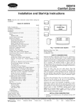
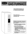
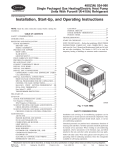
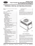
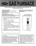
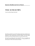
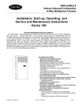
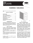
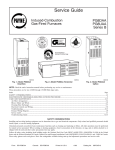
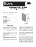
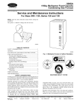
Two-Speed Furnace Control
Replacement Kit
Cancels: NEW
IIK 340M-40-86
10-04
Installation Instructions
Part No. 325879-751
NOTE: Read the entire instruction manual before starting the
installation.
3. All 115-volt neutrals are grouped together in one location of
board. (See Fig. 3.)
SAFETY CONSIDERATIONS
Installing and servicing of heating equipment can be hazardous
due to gas and electrical components. Only trained personnel
should install or service heating equipment.
4. Humidifier connection is removed from thermostat terminal
block. It is now a ¼ inch spade terminal, next to the thermostat
terminal block. (See Fig. 3.)
Untrained personnel can perform basic maintenance functions
such as cleaning and replacing filters. All other operations should
be performed by trained service personnel. When working on
heating equipment, observe precautions in the literature, on tags,
and on labels attached to the unit.
KIT CONTAINS
Control board
Wire harness adapter
Kit Wiring diagram
PART NUMBER
HK42FZ017
328156-701
328155-101( Rev A)
Follow all safety codes. Wear safety glasses and work gloves.
Have a fire extinguisher available.
TWINNING
Recognize safety information. This is the safety-alert symbol .
When you see this symbol on the furnace and in instructions or
manuals, be alert to the potential for personal injury.
The control board in this kit CAN also be twinned with any of
following circuit boards Part No. HK42FZ005, HK42FZ010, and
HK42FZ015.
Understand the signal words DANGER, WARNING, and CAUTION. These words are used with the safety-alert symbol. DANGER identifies the most serious hazards which will result in severe
personal injury or death. WARNING signifies a hazard which
could result in personal injury or death. CAUTION is used to
identify unsafe practices which may result in minor personal
injury or product and property damage. NOTE is used to highlight
suggestions which will result in enhanced installation, reliability,
or operation.
ELECTROSTATIC DISCHARGE (ESD) PRECAUTIONS
ELECTRICAL SHOCK, FIRE OR EXPLOSION
HAZARD
Failure to follow this warning could result in possible damage
to this equipment, serious personal injury, or death.
The ability to properly perform service on this equipment
requires certain expertise, mechanical skills, tools, and equipment. If you do not possess these, do not attempt to perform
any service on this equipment other than those procedures
recommended in the User’s Manual.
INTRODUCTION
This kit is a direct replacement for circuit boards Part No.
HK42FZ005, HK42FZ010, and HK42FZ015.
Changes to the operation of this control include:
1. The blower off delay selections are: 90, 120, 150 and 180
seconds.
2. A DHUM connection has been added to the thermostat
terminal block. When connected to a thermidistat and when
there is a call to dehumidify the cooling airflow will be
reduced to high-heat airflow. When jumpered to Y/Y2 it will
reduce the 90 second blower-off delay in the cooling mode, to
5 seconds.
UNIT DAMAGE HAZARD
Failure to follow this caution may damage furnace components.
Electrostatic discharge can affect electronic components.
Take precautions during furnace installation and servicing to
protect the furnace electronic control. Precautions will prevent electrostatic discharges from personnel and hand tools,
which are held during the procedure. These precautions will
help to avoid exposing the control to electrostatic discharge
by discharging static electricity build-up to ground.
1. Disconnect all power to the furnace. DO NOT TOUCH THE
CONTROL OR ANY WIRE CONNECTED TO THE CONTROL PRIOR TO DISCHARGING YOUR BODY’S ELECTROSTATIC CHARGE TO GROUND.
2. Ground yourself by touching your hand and tools to clean,
unpainted, metal surface of furnace close to control.
3. After touching chassis, you may proceed to service the
furnace. You will recharge your body with static electricity by
moving about or shuffling your feet. Reground yourself.
4. If you touch ungrounded objects (recharge your body with
static electricity), reground yourself. Use this procedure for
installed and uninstalled (ungrounded) furnaces.
5. Ground yourself again before handling a new control to
protect control from damage. If control is to be installed in
furnace, follow items 1 through 5 again before installing
control. Put all used AND new controls into containers before
touching ungrounded objects.
6. An ESD service kit (available from commercial sources) may
also be used to prevent ESD damage.
Manufacturer reserves the right to discontinue, or change at any time, specifications or designs without notice and without incurring obligations.
Book 1 4
PC 101
Catalog No. 535–80137
Printed in U.S.A.
Form 58MCA-12SI
Pg 1
10-04
Replaces: NEW
Tab 6a 8a
INSTALLATION
BLOWER OFF-DELAY
SELECTION CHART
Step 1—Removal of Existing Control
ELECTRICAL SHOCK AND UNIT DAMAGE
HAZARD
Failure to follow this warning could result in minor personal
injury, death or damage to furnace.
Label all wires prior to disconnection when servicing controls. Wiring errors can cause improper and dangerous
operation.
90
SEC
120
SEC
160
SEC
180
SEC
2 3
2 3
2 3
2 3
OFF
OFF
OFF
OFF
Fig. 1—Blower Off-Delay
A04133
b. The 3-pin connector which has 2 black wires and 1 red wire
connects to PL2 on the furnace control board. (See Fig. 3
and 4.)
1. Turn thermostat to OFF or set temperature to the lowest
setting.
c. The 2 white wires connect to the 115-volt Neutral spade
connections, located in front of PL1 on the new furnace
control board. (See Fig. 3 and 4.)
2. Turn off electrical supply to furnace.
3. Turn off gas supply to furnace.
5. Connect the transformer to the new furnace control board (See
Fig. 3.)
ELECTRICAL SHOCK, FIRE, EXPLOSION HAZARD
Failure to follow this warning could result in property damage
or minor personal injury/death.
Turn off gas and electrical supply before servicing this
furnace.
a. Blue wire to SEC-2 terminal. SEC-2 terminal is located
adjacent to the 3 amp fuse.
b. Red wire to SEC-1 terminal. SEC-1 terminal is located
adjacent to the 3 amp fuse.
c. Black wire to PR-1 terminal. PR-1 terminal is located
adjacent to PL2.
4. Removing blower door or access panel:
a. For 80 percent furnaces remove control access and blower
door.
d. White wire to one of the 115-volt Neutral spade connections located in front of PL1.
b. For 90 percent furnaces remove outer door assembly and
remove the two screws from blower access panel and set
aside.
6. Connect black wire from furnace auxiliary junction box to L1
on the new furnace control board. L1 is located on the blower
enable relay. (See Fig. 3.)
5. Disconnect thermostat and humidifier wires (if equipped).
7. Connect white wire from furnace auxiliary junction box to one
of the 115-volt Neutral spade connections located in front of
PL1. (See Fig. 3.)
6. Disconnect line voltage, blower, EAC, (if equipped) and
transformer wires.
8. Connect the blower motor leads to the new furnace control
board. (See Fig. 3.)
7. Remove retaining screws:
a. For 80 percent furnaces remove retaining screws and
remove furnace control board from bracket.
a. Connect the white blower motor lead to the BLW connection within the group of 115-volt Neutral spade connections.
b. For 90 percent furnaces remove two screws from blower
deck that hold the control box assembly. Lower control box
assembly. Remove retaining screw(s) from board and
remove board from control box assembly.
b. Connect the blower motor high-heat tap to the blower relay
connection marked HI HEAT.
8. Remove wiring harness connectors from furnace control
board.
c. Connect the blower motor low-heat tap to the blower relay
connection marked LO HEAT.
9. Inspect control and control box for evidence of water staining.
d. Connect the blower motor cool tap to the blower relay
connection marked COOL.
10. Correct any sources of water leakage (humidifier, evaporator
coil, vent system) into the control area.
e. Connect the remaining blower motor leads to SPARE-1
and SPARE-2.
Step 2—Installing the New Control
9. Connect all accessory wires.
1. Ground yourself! Handle furnace control board by edges.
10. For 90 percent furnaces reinstall control box assembly to
blower deck, by installing the two screws previously removed
from the blower deck.
2. Insert tab(s) of board into slots of control box (if required).
3. Install furnace control board retaining screw(s). Install wiring
harness adapter (Part# 328156-701) to two connections of the
existing furnace wiring harness. (See Fig. 4.)
a. The furnace harness 9-pin connector plugs into the mating
9-pin adapter harness connector.
11. Set blower off delay. Blower Off Delay Dip Switches are
located on the top-center portion of board. (See Fig. 3.) It is
factory set at 120 seconds. Use Fig. 1 to select a different
blower off delay.
b. The furnace harness 12-pin connector plugs into the mating
12-pin adapter harness connector.
12. If you are using a two-stage thermostat put setup switch 1 in
the ON position.
4. Connect the other end of the adapter harness (part# 328156701) to the new furnace control board.
13. Install kit wiring diagram 328155-101 in close proximity to
the furnace wiring diagram.
a. The 12-pin connector connects to PL1 on the furnace
control board. (See Fig. 3 and 4.)
14. Do not connect thermostat wires to control board until
Start-up and System Check-out is complete.
2
PARK
EAC-1
FU1
3
EAC-2
TRANSFORMER 24-V
CONNECTORS
SEC-1
SEC-2
3
HI-GAS
-HEAT
2
3-AMP
FUSE
LO-GAS
-HEAT
1
HI-COOL
6
L2
9
5
COM
8
4
L1
7
PR2
PARK-ISOLATED TERMINAL
FOR THE UNUSED PSC
MOTOR WIRE
BLOWER MOTOR
CONNECTION
PR1
PL2
HOT SURFACE IGNITOR
INDUCED DRAFT
MOTOR
CIRCUIT CONNECTOR
EAC-TERMINALS
115-VAC
1 AMP MAX.
LINE VOLTAGE
CONNECTIONS
10 11
12
7
9
8
4
5
6
1
2
3
PL1
GAS VALVE LOW VOLTAGE SAFETY
CIRCUIT CONNECTOR
TWINNING JUMPER
MASTER/SLAVE
LIGHT-EMITTING DIODE FOR
STATUS CODES
MASTER SLAVE
TWINNING BUSS CONNECTOR AND/OR
STATUS CODE RECALL CONNECTOR
G HUM
1
TWIN
TEST
LED
1
W2 COM W/W1 Y/Y2 R
24 V
HUM-HUMIDIFIER TERMINAL
CONNECTION (24-V 0.5 AMP MAX.)
24-V THERMOSTAT
TERMINALS
12 34
SETUP SWITCHES
HEAT STAGING AND
BLOWER OFF DELAY
PL4
ICM CONTROL
CONNECTION
A95360
Fig. 2—Old Furnace Control Board
d. Blower motor LO HEAT speed will be turned ON for 10
seconds.
Variable Speed Systems
For variable speed systems also wire the new control board as
follows:
e. Blower motor HI HEAT speed will be turned ON for 10
seconds.
1. The variable speed motor harness 6-pin connector that
plugged into PL4 on the old style furnace control board plugs
into PL3 on the new style furnace control board. (See Fig. 2
and 3.)
f. Blower motor COOL speed will be turned on for 10
seconds.
g. When the blower motor is turned OFF the inducer motor
will be switched to low-heat speed for 10 seconds.
2. The green wire from the variable speed motor labeled DEHUM connects to G on the furnace control if it was previously
connected to G on the old style furnace control board.
2. Repair, replace or service any component that does not work
properly during the self-test. The gas valve and humidifier are
not energized during self-test.
a. If so, you will have to cut the ¼ inch spade terminal off and
strip the wire to do this.
3. Turn power off.
b. If not, the green wire labeled DEHUM is probably spliced
to a thermostat wire that is connected to the DHUM
terminal of the Thermidistat. Leave it hooked up this way
and DO NOT connect it to the DHUM terminal on the new
furnace control board.
4. Release blower door switch.
NOTE: Current status code will be stored even when blower door
is removed.
5. Connect thermostat wires.
6. Install blower and access doors.
3. The 2 white wires previously connected to the ¼ inch HUM
spade terminal of the old furnace control board need to be
connected to the ¼ inch HUM spade terminal on the new
furnace control board. (See Fig. 2 and 3.)
7. Turn power back on.
8. Turn on gas supply to furnace.
Step 2—Flame Sensor Operation
SYSTEM CHECK-OUT
Step 1—Component Self Test
Connect a DC microampmeter in series with flame sensor. Initiate
a call for heat. After burners ignite and stabilize, measure flame
current. Nominal flame current is between 4.0 and 6.0 microamps
DC. If flame current is below 4.0 microamps DC, remove and
clean flame sensor with fine steel wool, or replace flame sensor.
1. To initiate component test sequence, ensure thermostat is
turned OFF or thermostat wires are disconnected. Turn power
on and manually close blower door switch. With a short piece
of wire, briefly short TEST/TWIN terminal to COM/24v
terminal.
Component test sequence is as follows:
The furnace control will lock-out when flame current falls to 0.5
microamps DC.
Check flame current in low-heat and high-heat.
a. Status LED will flash previous fault or status code #11 four
times then turn ON the inducer motor at high-heat speed.
Step 3—System Operation
1. Perform any other safety checks as deemed necessary (flame
safety, limit switch, vent system etc.).
b. Inducer motor will run for entire component test.
c. Hot surface igniter will be turned ON for 15 seconds, then
OFF.
2. Run unit through 1 complete call for heat cycle.
3
SETUP SWITCHES
LOW-HEAT ONLY AND
BLOWER OFF-DELAY
TWINNING AND/OR
COMPONENT TEST
TERMINAL
ACRDJ - AIR CONDITIONING
RELAY DISABLE JUMPER
ACRDJ
PLT
HUM
TRANSFORMER 24-VAC
CONNECTIONS
0.5-AMP024 VAC
PL1 - LOW VOLTAGE MAIN
HARNESS CONNECTOR
LED
FUSE 3-AMP
STAT
SEC-2
NEUTRAL-L2
PL3
OD E
EAC-2
PL1
LED OPERATION &
DIAGNOSTIC LIGHT
SEC-1
US C
3-AMP FUSE
TEST/TWIN
R
HUMIDIFIER TERMINAL
(24-VAC 0.5 AMP MAX.)
1 2 3
Y1 DHUM G COM WW1 Y/Y2
24V
24-V-THERMOSTAT
TERMINALS
ON
OFF
W2
LHT
OFF
DLY
1
PL3 -ICM CONTROL
HARNESS CONNECTOR
1
BLW
115-VAC (L2) NEUTRAL
CONNECTIONS
BHI/LOR
BHT/CLR
BLWR
HI HEAT
IDM
COOL
PR-1
IHI/LOR
EAC-1
PL2
SPARE-2
L1
SPARE-2
1
1-AMP@115 VAC
COOL
SPARE-1
SPARE-1
BLOWER SPEED
SELECTION TERMINALS
HSIR
IDR
LO HEAT
HI HEAT
LO HEAT
HSI
HI LO
115-VAC (L1) LINE
VOLTAGE CONNECTION
PL2 - HOT SURFACE
IGNITER & INDUCER
MOTOR CONNECTOR
EAC-1 TERMINAL
(115-VAC 1.0 AMP MAX.)
A02017
Fig. 3—New Furnace Control Board
To PL1 on new board
To 12-pin connector
(PL1) of furnace wiring
harness
To PL2 on new board
To 9-pin connector (PL2)
of furnace wiiring
harness
To neutral connections
on new board
A04124
Fig. 4—Wire Harness Adapter
Copyright 2004 Carrier Corporation
340m4086
Manufacturer reserves the right to discontinue, or change at any time, specifications or designs without notice and without incurring obligations.
Book 1 4
PC 101
Catalog No. 535–80137
Printed in U.S.A.
Form 58MCA-12SI
Pg 4
10-04
Replaces: NEW
Tab 6a 8a