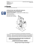
1
SERVICE MANUAL AH-13-01.1 May - 2013 Ransburg NO. 2 PROCESS HANDGUN ELECTRIC MOTOR VERSION MODEL: 19372 IMPORTANT: Before using this equipment, carefully read SAFETY PRECAUTIONS, starting on page 1, and all instructions in this manual. Keep this Service Manual for future reference. Service Manual Price: $50.00 (U.S.) Ransburg NOTE: This manual has been changed from revision AH-13-01 to revision AH-13-01.1 Reasons for this change are noted under “Manual Change Summary” on page 56 of this manual. 1. Removed the di-electric oil from the installation - no longer used (Page 10 & 11). AH-13-01.1 Ransburg No. 2 Process Electric Motor Version - Contents CONTENTS PAGE SAFETY: 1-5 SAFETY PRECAUTIONS .......................................................................................................... 1 HAZARDS / SAFEGUARDS .. .................................................................................................... 2-5 INTRODUCTION: 6-8 GENERAL DESCRIPTION ........................................................................................................ 6 SPECIFICATIONS ..................................................................................................................... 7 GUN AND POWER SUPPLY FEATURES ................................................................................. 8 INSTALLATION: 9-14 PRE-INSTALLATION REQUIREMENTS ................................................................................... 9 SAFEGUARDS .......................................................................................................................... 9 EQUIPMENT INSTALLATION.................................................................................................... 9 POWER SUPPLY....................................................................................................................... 10 FLUID HOSE.............................................................................................................................. 10 FLUID FITTING INSTALLATION PROCEDURE........................................................................ 12 INSTALLATION FEED TUBE, BELL, BRUSH............................................................................ 12 ACCESSORY INSTALLATION................................................................................................... 13 NO. 2 HANDGUN BRUSH POSITIONING AND WEAR............................................................. 14 PAINT......................................................................................................................................... 15 OPERATION: 16-21 PROCEDURES ......................................................................................................................... 16-17 OPERATIONS NEAR COMPUTERS OR OTHER ELECTRONIC DEVICES ........................... 17-18 SHUTDOWN.............................................................................................................................. 18 END OF SHIFT........................................................................................................................... 18-19 COLOR CHANGE...................................................................................................................... 19-20 GUN ELECTRICAL OUTPUT..................................................................................................... 20 GUN SHORT CIRCUIT CURRENT (SCI) TEST......................................................................... 21 MAINTENANCE: 22-41 EFFECTS OF SOLVENTS ........................................................................................................ 22 NO. 2 HANGUN ......................................................................................................................... 23 SCHEDULES ............................................................................................................................ 23-24 TEST PROCEDURES ............................................................................................................... 24 ELECTRICAL TESTING ............................................................................................................ 24 TOOLS REQUIRED .................................................................................................................. 24-25 REPAIR PROCEDURES ........................................................................................................... 25-27 CABLE/ELECTRIC MOTOR ASSEMBLY .................................................................................. 27-28 MOTOR ASSEMBLY REPACEMENT......................................................................................... 28 HANDLE ASSEMBLY................................................................................................................. 28-32 BARREL ASSEMBLY ................................................................................................................ 33-36 9060 FUSE REPLACEMENT..................................................................................................... 36-37 TROUBLESHOOTING GUIDE .................................................................................................. 38-41 AH-13-01.1 Ransburg No. 2 Process Electric Motor Version - Contents CONTENTS (Cont.) PAGE PARTS IDENTIFICATION: 42-54 19372-AAU PARTS BREAKOUT .............................................................................................. 42 CABLE / MOTOR PARTS LIST ................................................................................................. 43 7233-00 HANDLE PARTS LIST................................................................................................. 44 NEEDLE VALVE ASSEMBLY PARTS LIST ............................................................................... 45 BARREL PARTS LIST ............................................................................................................... 46 8340-XX FLUID HOSE PARTS AND ASSEMBLIES ................................................................. 47 FEED TUBE PARTS .................................................................................................................. 48 BRUSH ASSEMBLY PARTS ..................................................................................................... 48 FLUID FILTER PARTS .............................................................................................................. 49 BELL SPARE PARTS AND ASSEMBLIES ................................................................................ 50 9060 SPARE PARTS LIST ........................................................................................................ 51 RECOMMENDED SPARE PARTS LIST ................................................................................... 52 9096-00 NO. 2 GUN REPAIR KIT PARTS LIST......................................................................... 53 ACCESSORIES......................................................................................................................... 54 WARRANTY POLICIES: 55 LIMITED WARRANTY ............................................................................................................... 55 MANUAL CHANGES: 56 SUMMARY ................................................................................................................................ 56 AH-13-01.1 Ransburg No. 2 Process Electric Motor Version - Safety SAFETY SAFETY PRECAUTIONS Before operating, maintaining or servicing any Ransburg electrostatic coating system, read and understand all of the technical and safety literature for your Ransburg products. This manual contains information that is important for you to know and understand. This information relates to USER SAFETY and PREVENTING EQUIPMENT PROBLEMS. To help you recognize this information, we use the following symbols. Please pay particular attention to these sections. A WARNING! States information to alert you to a situation that might cause serious injury if instructions are not followed. A CAUTION! States information that tells how to prevent damage to equipment or how to avoid a situation that might cause minor injury. A NOTE is information relevant to the procedure in progress. While this manual lists standard specifications and service procedures, some minor deviations may be found between this literature and your equipment. Differences in local codes and plant requirements, material delivery requirements, etc., make such variations inevitable. Compare this manual with your system installation drawings and appropriate Ransburg equipment manuals to reconcile such differences. ! WARNING The user MUST read and be familiar with the Safety Section in this manual and the Ransburg safety literature therein identified. This hand held device is intended to be used by trained personnel ONLY. This manual MUST be read and thoroughly understood by ALL personnel who operate, clean or maintain this equipment! Special care should be taken to ensure that the WARNINGS and safety requirements for operating and servicing the equipment are followed. The user should be aware of and adhere to ALL local building and fire codes and ordinances as well as NFPA33 EN 50176 SAFETY STANDARD, or applicable country safety standards prior to installing, operating, and/or servicing this equipment. ! WARNING The hazards shown on the following page may occur during the normal use of this equipment. Please read the hazard chart beginning on page 2. Careful study and continued use of this manual will provide a better understanding of the equipment and process, resulting in more efficient operation, longer trouble-free service and faster, easier troubleshooting. If you do not have the manuals and safety literature for your Ransburg system, contact your local Ransburg representative or Ransburg. 1 AH-13-01.1 Ransburg AREA Tells where hazards may occur. Spray Area No. 2 Process Electric Motor Handgun - Safety HAZARD Tells what the hazard is. SAFEGUARDS Tells how to avoid the hazard. Fire Hazard Improper or inadequate operation and maintenance procedures will cause a fire hazard. Protection against inadvertent arcing that is capable of causing fire or explosion is lost if any safety interlocks are disabled during operation. Frequent power supply shutdown indicates a problem in the system requiring correction. Fire extinguishing equipment must be present in the spray area and tested periodically. Spray areas must be kept clean to prevent the accumulation of combustible residues. Smoking must never be allowed in the spray area. The high voltage supplied to the atomizer must be turned off prior to cleaning, flushing or maintenance. When using solvents for cleaning: •• Those used for equipment flushing should •• •• have flash points equal to or higher than those of the coating material. Those solvents used for cleaning must have a flash point at minimum of 5oC (9oF) greater than the ambient temperature. It is the end users responsibility to insure this condition is met.). Spray booth ventilation must be kept at the rates required by NFPA-33, OSHA, country, and local codes. In addition, ventilation must be maintained during cleaning operations using flammable or combustible solvents. Electrostatic arcing must be prevented. Safe sparking distance must be maintained between the parts being coated and the applicator. A distance of 1 inch for every 10KV of output voltage is required at all times. Test only in areas free of combustible material. Testing may require high voltage to be on, but only as instructed. Non-factory replacement parts or unauthorized equipment modifications may cause fire or injury. If used, the key switch bypass is intended for use only during setup operations. Production should never be done with safety interlocks disabled. Never use equipment intended for use in waterborne installations to spray solvent based materials. The paint process and equipment should be set up and operated in accordance with NFPA33, NEC, OSHA, local, country, and European Health and Safety Norms. AH-13-01.1 2 Ransburg No. 2 Process Electric Motor Version - Safety AREA Tells where hazards may occur. Spray Area HAZARD Tells what the hazard is. SAFEGUARDS Tells how to avoid the hazard. Explosion Hazard Improper or inadequate operation and maintenance procedures will cause a fire hazard. Protection against inadvertent arcing that is capable of causing fire or explosion is lost if any safety interlocks are disabled during operation. Frequent Power Supply or Controller shutdown indicates a problem in the system requiring correction. Electrostatic arcing must be prevented. Safe sparking distance must be maintained between the parts being coated and the applicator. A distance of 1 inch for every 10KV of output voltage is required at all times. Unless specifically approved for use in hazardous locations, all electrical equipment must be located outside Class I or II, Division 1 or 2 hazardous areas, in accordance with NFPA33. Test only in areas free of flammable or combustible materials. The current overload sensitivity (if equipped) MUST be set as described in the corresponding section of the equipment manual. Protection against inadvertent arcing that is capable of causing fire or explosion is lost if the current overload sensitivity is not properly set. Frequent power supply shutdown indicates a problem in the system which requires correction. Always turn the control panel power off prior to flushing, cleaning, or working on spray system equipment. Before turning high voltage on, make sure no objects are within the safe sparking distance. Ensure that the control panel is interlocked with the ventilation system and conveyor in accordance with NFPA-33, EN 50176. Have fire extinguishing equipment readily available and tested periodically. General Use and Maintenance 3 Improper operation or maintenance may create a hazard. Personnel must be given training in accodance with the requirements of NFPA-33, EN 50-176. Personnel must be properly trained in the use of this equipment. Instructions and safety precautions must be read and understood prior to using this equipment. Comply with appropriate local, state, and national codes governing ventilation, fire protection, operation maintenance, and housekeeping. AH-13-01.1 Ransburg AREA Tells where hazards may occur. Spray Area / High Voltage Equipment No. 2 Process Electric Motor Version - Safety HAZARD Tells what the hazard is. SAFEGUARDS Tells how to avoid the hazard. Electrical Discharge There is a high voltage device that can induce an electrical charge on ungrounded objects which is capable of igniting coating materials. Inadequate grounding will cause a spark hazard. A spark can ignite many coating materials and cause a fire or explosion. Parts being sprayed and operators in the spray area must be properly grounded. Parts being sprayed must be supported on conveyors or hangers that are properly grounded. The resistance between the part and earth ground must not exceed 1 meg ohm. (Refer to NFPA-33.) Operators must be grounded. Rubber soled insulating shoes should not be worn. Grounding straps on wrists or legs may be used to assure adequate ground contact. Operators must not be wearing or carrying any ungrounded metal objects. When using an electrostatic handgun, operators must assure contact with the handle of the applicator via conductive gloves or gloves with the palm section cut out. NOTE: REFER TO NFPA-33 OR SPECIFIC COUNTRY SAFETY CODES REGARDING PROPER OPERATOR GROUNDING. All electrically conductive objects in the spray area, with the exception of those objects required by the process to be at high voltage, must be grounded. Grounded conductive flooring must be provided in the spray area. Always turn off the power supply prior to flushing, cleaning, or working on spray system equipment. Unless specifically approved for use in hazardous locations, all electrical equipment must be located outside Class I or II, Division 1 or 2 hazardous areas, in accordance with NFPA-33. AH-13-01.1 4 Ransburg No. 2 Process Electric Motor Version - Safety AREA Tells where hazards may occur. Electrical Equipment HAZARD Tells what the hazard is. Tells how to avoid the hazard. Electrical Discharge High voltage equipment is utilized in the process. Arcing in the vicinity of flammable or combustible materials may occur. Personnel are exposed to high voltage during operation and maintenance. Protection against inadvertent arcing that may cause a fire or explosion is lost if safety circuits are disabled during operation. Frequent power supply shutdown indicates a problem in the system which requires correction. An electrical arc can ignite coating materials and cause a fire or explosion. Toxic Substances SAFEGUARDS Certain material may be harmful if inhaled, or if there is contact with the skin. Unless specifically approved for use in hazardous locations, the power supply, control cabinet, and all other electrical equipment must be located outside Class I or II, Division 1 and 2 hazardous areas in accordance with NFPA-33 and EN 50176. Turn the power supply OFF before working on the equipment. Test only in areas free of flammable or combustible material. Testing may require high voltage to be on, but only as instructed. Production should never be done with the safety circuits disabled. Before turning the high voltage on, make sure no objects are within the sparking distance. Follow the requirements of the Material Safety Data Sheet supplied by coating material manufacturer. Adequate exhaust must be provided to keep the air free of accumulations of toxic materials. Use a mask or respirator whenever there is a chance of inhaling sprayed materials. The mask must be compatible with the material being sprayed and its concentration. Equipment must be as prescribed by an industrial hygienist or safety expert, and be approved. Spray Area Explosion Hazard – Incompatible Materials Halogenated hydrocarbon solvents for example: methylene chloride and 1,1,1,-Trichloroethane are not chemically compatible with the aluminum that might be used in many system components. The chemical reaction caused by these solvents reacting with aluminum can become violent and lead to an equipment explosion. 5 Aluminum is widely used in other spray application equipment - such as material pumps, regulators, triggering valves, etc. Halogenated hydrocarbon solvents must never be used with aluminum equipment during spraying, flushing, or cleaning. Read the label or data sheet for the material you intend to spray. If in doubt as to whether or not a coating or cleaning material is compatible, contact your coating supplier. Any other type of solvent may be used with aluminum equipment. AH-13-01.1 Ransburg No. 2 Process Electric Motor Version - Introduction INTRODUCTION GENERAL DESCRIPTION This is a method of applying electrostatically atomized coating material. The No. 2 Electric Process Handgun system applies a high voltage, DC negative charge to the applicator bell, creating an electrostatic field between the bell and the target object. The target is electrically grounded through its support (which may be stationary or moving) or through an electrical connection to a known earth ground. A regulated pressure fluid system delivers coating material to the electric motor driven bell when the gun is triggered. There, the fluid travels across the face of the rotating bell and is charged. The fluid is atomized at the edge of the bell forming a fine mist, which under the influence of the electrostatic field is attracted to and deposited on the target object. The forces between the charged particles and the grounded target are sufficient to turn most normal overspray around and deposit it on the rear surface of the target. Therefore, most of the spray is deposited and overspray is controlled. This process makes the No. 2 Electric Process Handgun one of the most efficient electrostatic spray products on the market. The No. 2 Electric Process Handgun applies a DC negative charge to the coating materials at the point of atomization. The electrostatic charge allows a more efficient, uniform application of coating material to the front, edges, sides, and back of products, making it highly suitable for applying coatings to a variety of surface configurations; large targets, tubular products, small parts, fencing, etc. Because it is a grounded fluid system, it is highly suitable for applying a AH-13-01.1 wide range of solvent reduced coatings such as enamels, epoxies, etc. One of the many features of the No. 2 Electric Process Handgun is that the electrical discharge, which is available from the resistive charging brush, is limited to the optimum combination of safety and efficiency. The No. 2 Electric Process Handgun system includes the Hand Gun, the High Voltage Power Supply, the High Voltage Cable, and Fluid Hose. This unit contains the 19372-XX No. 2 handgun electric motor version and the 80102-21X 9060 power supply along with several required accessories. Below illustrates the ordering matrix available. 19372 - AA U No. 2 Electric Motor Indicates Unit Indicates Cable Length AA is 25’ (7.6 m) Cable Length 36’ (11 m) Cable Length 50’ (15.2 m) Cable Length 75’ (22.9 m) Cable Length 100’ (30.4 m) Cable Length U - Left blank gun only - U Indicates 80102-21X Power Supply 6 Ransburg No. 2 Process Electric Motor Version - Introduction SPECIFICATIONS Environmental/Physical Mechanical Length: 508 cm (20 inches) Fluid Input Pressure: 3.45 bar (50psig) Weight: 1588 g (56 ounces) Air Input Pressure: 6.90 bar (100 psig) Fluid Delivery Rate: 2-3/4” Bell: Rate: (maximum) Electrical Input Voltage: 110 or 220 VAC 50/60 Hertz Output Voltage: 90 kV DC (negative) Current: 30-50 microamperes (operating) SCI (From Brush):115 microamperes (maximum) 75 cc/minute (2.5 fl oz/minute) 4” Bell: Rate: 120 cc/minute (4 fl oz/minute) 6” Bell: Rate: 180 cc/minute (6 fl oz/minute) Application Rate: 2-3/4” Bell: Rate: (maximum) 5-7 ft2/minute (.46-.65 m2/minute) 4” Bell: Rate: 10-12 ft2/minute (.93-1.11 m2 /minute) 6” Bell: Rate: 15-18 ft2/minute (.93-1.11 m2 /minute) Note: conversion 29.5 cc (ml) = 1 fluid oz 7 AH-13-01.1 Ransburg No. 2 Process Electric Motor Version - Introduction Figure 1: Gun Features / Model 19372-XX MODEL 19372 -XX GUN FEATURES Item Description 1 Handle Assembly 2Trigger 3 Trigger Adjustment 4 Resistor Housing 5 Contact Brush 6 Rim Assembly Item Description 7 Drive Shaft and Seal 8Barrel 9 On-Off Switch 10 Cable/Electric Motor Assembly 11 Hv Cable Assembly 12 Fluid Inlet Fitting (9/16-18 l.h. th’d.) Figure 2: 9060 Power Supply Features / Model 80102-211 9060 POWER SUPPLY FEATURES / MODEL 80102-211 Item Description 1 2 3 4 5 6 7 Kv Meter High Voltage On Indicator Reset Button Ma Meter Fault Indicator On-Off Switch “One Touch” Kv Setpoint Button AH-13-01.1 Item Description 8 Kv Setpoint/Adjust Buttons 9 Air Flow Switch Connections 10 High Voltage Cable Connector 11Fuses 12 Grounding Lug 13 Ac Inlet Receptacle 14 Door Key Lock 8 Ransburg No. 2 Process Electric Motor Version - Installation INSTALLATION PRE-INSTALLATION REQUIREMENTS 1. Provide approved electrical wiring to the power supply. The 9060 power supply must be located a minimum of 6.1m (20’) outside of the hazardous spray area. 2. Make sure the operating location has adequate grounding facilities, such as electrical conduit, steel building columns, metal water pipes, or other earth grounded objects. 3. Furnish a paint pressure pot with air regulator (or other accepted pressure system). The regulator MUST have a reliable control, with a recommended gauge range of 0-2.1 bar (0-30 psig). 4. Provide proper ventilation. (See “Safety” section of this manual.) 5. Ensure that the target object to be coated and all surrounding objects are grounded to a known, earth ground by a separate ground wire attachment. ! CAUTION Do not use the power supply ground wire to ground target objects. The targets objects must have separate true earth ground for best efficiency. SAFEGUARDS When operating this equipment in the vicinity of computers, word processors, and/or other electronic equipment, special care MUST be taken to ensure that damage does not occur from electrical energy discharges. (See Ransburg “Safety Literature” for further information regarding application.) 9 The following guidelines can be used: •• It is highly recommended, whenever possible, that ALL electronic components or equipment be removed from the spray area. This includes computer software such as tapes, disks, diskettes, etc., located inside and/or around the spray area. •• If the static shielding of a unit is NOT KNOWN, all electronic components (such as terminals, screens, and cables) should be completely wrapped in aluminum foil and grounded to a true earth ground. •• When painting electrical control panels or consoles, wrap all push-buttons, switches, meters, or pilot lights with aluminum foil and ground to the panel or other earth ground. EQUIPMENT INSTALLATION ! WARNING NEVER wrap the applicator, associated valves and tubing, and supporting hardware in plastic to keep it clean. A surface charge may build up on the plastic surface and discharge to the nearest grounded object. Efficiency of the applicator will also be reduced and damage or failure of the applicator’s components may occur. WRAPPING THESE COMPONENTS IN PLASTIC WILL VOID WARRANTY AH-13-01.1 Ransburg No. 2 Process Electric Motor Version - Installation Before attempting to install the equipment, ensure that all the necessary components are available (see “Parts Identification” section of this manual). In addition, read all the technical and safety literature that is provided. If the literature is not available, contact your local Ransburg Distributor where the equipment was purchased. ! 4. Apply a generous amount of LSCH 0009 on the power supply end of the cable as shown in figure 3. 5. Attach the female nut of the high voltage cable to the male threads of the connection of the power supply. WARNING The power source wiring and the power supply connections to it MUST meet all local fire and electrical code standards and comply with all appropriate local and national health and safety codes. All power supplies MUST be grounded to a known true earth ground before any other connections are made or functions performed. DO NOT use the power supply ground wire to ground the target objects (use LSME4000-00 clamp assembly)! POWER SUPPLY (Refer to Figure 2) 1. The high voltage power supply MUST be located at least 6.1 m (20 feet) from the spraying operation. If a spray booth is used, the power supply may be located 1.5 m (5 feet) from the nearest opening and outside the booth . 2. If a line cord is used instead of a permanent conduit connection, ensure the ground lead is present on the plug. Ensure that the electrical outlet is properly wired by using the circuit tester (20868-00). Attach the green ground wire to a proven, true earth ground (i.e., water pipe or electrical conduit). ! WARNING Where the applicator is to be used without a booth, the power supply must located a minimum of 6.1 m (20 feet) from the target being sprayed. The target Earth Ground and Power Supply earth ground must be separate earth ground connections. Any fluid hose that is are user supplied must be rated for the maximum pressures used for this applicator. FLUID HOSE (Refer to Figure 4) Install the fluid filter (Item 5) to the applicator, then to the fluid delivery hose. Attach one end of the fluid hose to the adapter (Item 6) (Refer to figure 4). This adapter has a 3/8-18 NPSM (F) for attachment to a suitable fluid source. To meet various length requirements, the hose fitting on one end has not been attached. Figure 5 illustrates the assembly procedure for attaching the loose fitting. 3. After the power supply is grounded to a suitable earth ground, the high voltage cable may be connected. Prior to connection of the high voltage cable 15 to 30 ml of 3614-00 (supplied with applicator ) di-electric oil needs to be added to the power supply. Refer to figure 3 for illustration of where the oil should be inserted. AH-13-01.1 10 Ransburg No. 2 Process Electric Motor Version - Installation Figure 3: LSCH 0009 Di-Electric Application Figure 4: Equipment Installation Diagram EQUIPMENT INSTALLATION DIAGRAM Item# 1 2 3 4 5 6 7 8 9 11 (Figure 4) Description 9060 Power Supply 80102-21X Connected to True Earth Ground High Voltage Cable Connection to Power Supply 19372 -XX #2 Electric Motor Applicator Earth grounded regulated paint supply 76938-02 Inline Fluid Filter 8340-25 Fluid Hose 7244-00 Adapter 9/16-18 LH (M) to 3/8-18 NPSM(F) Earth Grounded Target Bell Cleaning Can AH-13-01.1 Ransburg No. 2 Process Electric Motor Version - Installation INSTALLATION FEED TUBE, BELL, BRUSH 1. Install the proper feed tube into the opening in the applicator. See figure 6. Position the tube at approximately as shown in the figure. 2. Insert the 3695-00 (item 2) brush into the barrel. Position it as shown in figure 6. Figure 5: Fluid Fitting Assembly Procedure 3. Install the bell over the shaft. Hold the shaft of the applicator and rotate the bell onto the shaft until the bell is completely seated. Align the set screw and the flat on the shaft. Tighten the set screw at the bell hub hand tight. (Refer to Figure 7) FLUID FITTING ASSEMBLY PROCEDURE (Figure 5) Item # 1 2 3 4 Description 4.5 mm (3/16”) Hex Key Stem Ferrule Hose, Fluid FLUID FITTING INSTALLATION PROCEDURE 1. Lubricate all fittings with dielectric grease. 2. Screw ferrule (item 3) counterclockwise onto hose (item 4) until it bottoms, then back it off approximately 3.2 mm (1/8”). 3. Install nut over union stem and start the stem into the hose. 4. Using a 4.5 mm hex key (3/16-inch ), screw the union stem into the hose until it bottoms against the ferrule. AH-13-01.1 Figure 6: Initial Position of Feed Tube and Brush INITIAL POSITION OF FEED TUBE AND BRUSH (Figure 6) Item # Description 1 Feed Tube 3700-00 for 4” Bell Feed Tube 6335-00 for 2 3/4” Bell Feed Tube 4076-00 for 6” Bell 2 3695-00 Brush 12 Ransburg No. 2 Process Electric Motor Version - Installation ! WARNING Replacing the plastic set screw with one of conductive material (metal) will cause a hazardous condition to exist, capable of producing an electrical discharge possible of sparking a fire. In all cases use the plastic screw provided or provided as a spare part. ACCESSORY INSTALLATION Included with the unit are two accessory items: • Bell cleaning can and the gun holder. WARNING ! Insure ground line of the bell cleaning can is attached to true earth ground when either solvent is stored in the can or the can in use. The Bell Cleaning Can provides a convenient and portable method of removing excess materials from the bell cup at the conclusion of spray. ! CAUTION Insure any cleaning solvent used meets criteria listed in the maintenance section of this manual. Figure 7: Installing Bell on Shaft The gun holder provides a method to mount and store the applicator when not in use. INSTALLING BELL ON SHAFT (Figure 7) Item # 1 2 3 4 Description No. 2 Motor Shaft Shaft Locating Flat Bell Set Screw Bell 4. Re-position the feed tube in the bell cavity at approximately the 4 to 5 o’clock position. The feed tube should NOT rub on the bell. Adjust the feed tube if necessary, by rotating it or sliding it forward or backward in the barrel. NOTE The bell and feed tube MUST be matched to ensure proper fluid feed into the bell cavity. The following chart will assist in selecting the proper bell and feed tube combination: 13 Bell Cup Cleaning Can 5170 Gun Holder 3936 Figure 8: Bell Cleaning Can and Gun Holder BELL CLEANING CAN GUN HOLDER (Figure 8) Bell Size Feed Tube # 2 3/4 “ 4” 6” 6335-00 3700-00 4076-00 Position of Tube @2 o’clock @4-5 o’clock @4-5 o’clock AH-13-01.1 Ransburg No. 2 Process Electric Motor Version - Installation NO. 2 HANDGUN BRUSH POSITIONING AND WEAR (Refer to Figure 9) When installing the electrical contact brush (369500), it is important that it is properly positioned to provide LIGHT CONTACT with the bell conductive coating. Excessive contact pressure from the contact brush will wear away the conductive coating or the brush tip, causing poor electrical contact. The small plastic pad at the tip of the brush arm should lightly contact the black bell coating, not the wire. The wire should never contact the coating. The tip of the brush should not extend past the edge of the bell cup or into the radius at the edge (see Figure 9). The brush should normally have a slight curve to the arm. The more pressure applied the lesser the curve (see Figure 4). The tip of the brush assembly must be inspected prior to each use for wear. When one-half (1/2) of the plastic tip is worn away the brush assembly should be replaced (see Figure 10). Figure 9-3: Brush and Feed Tube Positioning Figure 9-1: Un-Installed Brush Shape Figure 9-4: Brush Contact Area Figure 9-2: Brush Contact Position AH-13-01.1 14 Ransburg No. 2 Process Electric Motor Version - Installation NOTE When the radius portion of the brush plastic tip is gone, the brush will need to be replaced soon. PAINT A proper paint mixture is essential to the electrostatic operation. Due to the method of electrostatic atomization the viscosity and conductivity levels of the paint are important to ensure proper application. Paint test equipment such as the test assembly (76652-03) for testing paint electrical resistivity, may be purchased through your Ransburg distributor. (See “Paint and Solvent Specifications” in the “Appendix” section of this service manual.) Most paint suppliers may be of assistance in pre-adjusting the paint for proper electrostatic sprayability. ! Figure 10: Brush Tip New and Worn WARNING When the gun switch is ON, the bell will be rotating and high voltage will be activated. Steps MUST be taken to ensure grounding of personnel and equipment for safety. Electrical shock may occur if the equipment and/or personel are NOT grounded. BRUSH TIP NEW AND WORN (Figure 10) Item # 1 2 15 Description New Brush Tip Worn Brush Tip AH-13-01.1 Ransburg No. 2 Process Electric Motor Version - Operation OPERATION PROCEDURES Prior to operating the No. 2 Handgun, ensure that the equipment is installed properly (see “Installation” section of this service manual). Observe and follow the safety requirements at ALL times. 4. Turn the 9060 power “ON-OFF” switch on the front panel to the “ON” position as shown in Figure 12. The unit will power up, but high voltage will not be on at this point. because the voltage is interlocked to the electric motor through the “ON-OFF” switch on the applicator. 1. Inspect the rotating bell assembly to ensure that it is clean and is not chipped. Replace or clean the bell assembly when necessary. 2. Set the paint fluid pressure at 0.2 to 0.3 bar (3 to 4 psi ). Adjust the pressure up or down for the desired fluid delivery. Higher fluid pressure may be needed with higher viscosity material, longer hoses, or higher fluid deliveries. 3. Insure the “ON-OFF” switch is in the off position. (See figure 11) Figure 12: 9060 Power “ON-OFF” Switch 9060 POWER “ON - OFF” SWITCH (Figure 12) Item # 1 2 Description Power “ON - OFF” Switch HV on Indicator 5. Actuate the “ON-OFF” switch push the post to the “ON” position. The electric motor will begin turning and voltage will be present at the bell. The HV On indicator on the 9060 will illuminate when voltage is on. Figure 11: “ON - OFF” Switch Location ON - OFF SWITCH LOCATION (Figure 11) Item # 1 AH-13-01.1 Description “ON - OFF” Switch 6. Hold the No. 2 handgun perpendicular to, and 13 to 18 cm (4 to 7 inches ) from the part being coated. Trigger the handgun and observe the atomization of the coating material. ! CAUTION The application process works best when the bell is positioned perpendicular to the grounded target. Following this method avoids paint wrap back onto the operator or nearby objects. 16 Ransburg No. 2 Process Electric Motor Version - Operation NOTE The quality of atomization can be tested by shooting a “donut” test pattern on a grounded flat surface at approximately a 15.2 cm (6-inch) target distance. Coarse atomization may be caused by excessive fluid delivery (high fluid pressure or wrong bell size) or improper electrical resistance of the coating material. Adjust parameters according to atomization quality and results. 7. Pulling the applicator trigger to obtain material flow, move the No. 2 handgun in a smooth horizontal or vertical line or in a smooth circular motion, maintaining a constant distance between the target and the bell surface. (See Ransburg manual “No. 2 Handgun Spray Techniques”.) 8. When complete release the trigger to stop fluid flow. 9. Turn the “ON - OFF” switch to the “OFF” position. 10. Turn the power switch to the “Off” position on the power supply. NOTE For an accurate measurement of paint delivery with any paint being used, turn the handgun motor OFF, and remove the bell. Using a graduated cylinder or beaker and a stopwatch, trigger the gun and collect the fluid for one minute. Measure the paint volume collected to get fluid flow rate per minute. See maximum “Fluid Delivery Rate” under “Specifications” in the “Introduction” section of this manual. 17 OPERATIONS NEAR COMPUTERS OR OTHER ELECTRONIC DEVICES For over 50 years, the No. 2 Electric Process Handgun has been the most widely used tool by the on-site painting industry for the refinishing of office furniture, office panels, lockers, school furniture, and thoussands of other items. Quite often we are asked about the dangers and possible damage to computers, phone systems, word processors, and electronically keyed security systems when electrostatic painting is done nearby. Concerning those types of applications or any microprocessor base equipment, the following facts should be noted: 1. The No. 2 Electric Process Handgun is not electro-magnetic. It is electrostatic (much like the static from carpets or wool and synthetic clothing), and works at an output of 90 kilovolts at 30-50 microamperes current draw. (115 microamperes maximum short circuit current). ! WARNING All conductive objects in the area of spray must be grounded to earth ground. (Ref. EN 50 176, NFPA-33) 2. Unlike x-rays, electrostatic does not go “through” objects. 3. Some computers, phone systems, or word processors are now shielded by the manufacturer against outside static. 4. If the static shielding of a unit is unknown, the keyboard, CPU (central processing unit), monitor, or phone and its cable preferably should be removed from the immediate painting area for protection of the device. If this is not feasible, they should be completely wrapped in aluminum foil that is grounded to an earth ground. This will create a “Faraday cage” around the computerized device. AH-13-01.1 Ransburg No. 2 Process Electric Motor Version - Operation 5. Electrical sparks of all types create an R.F. energy (radio frequency) that may radiate through the air and enter into electronic circuits. The resulting damage is unpredictable. 6. Computer software such as tapes, disks, diskettes, etc., should be removed from inside of and from the immediately surrounding area of any enclosures that are to be painted. 7. Lightning or electrostatic voltage sparking into an A.C. circuit can create “spikes” or electro-magnetic pulse (EMP) that can cause unpredictable damage to electronic hardware. 8. Surge suppressors are available that may help protect appliances from “spikes” of current if the suppressor is in the AC line supplying the appliance. 9. When painting any type of electrical control panel or console it is generally not known if all push-button, switches, meters, or pilot lights are properly grounded. In view of this, it is desirable to cover all of these items with aluminum foil which is grounded to the panel or another earth ground. 10. All on-site painting companies should have adequate liability insurance to protect them in the event of any real or perceived damage as a result of their operations. In view of the above unknown and possible uncontrolled conditions, Ransburg does not recommend the electrostatic spray painting of computer cabinets, consoles, or painting in close proximity to these devices. SHUTDOWN These steps are to be followed during a shutdown for short periods such as breaks, lunch, downtime, etc. ! WARNING BEFORE attempting any cleaning or color change procedures, the high voltage and the AC power to the power supply MUST be turned OFF! AH-13-01.1 ! CAUTION The bell MUST be cleaned if the gun ill not be operated again within a few minutes. If two component catalyzed paint is used, frequent bell cleaning and flushing may be required. (See “Color Change” in the “Operation” section.) 1. Place the feed tube in the one o’clock position. Loosen the set screw on the bell hub. Then hold the shaft collar with one hand and turn the bell on the shaft with the other hand as you pull it forward off the shaft. 2. Clean the bell with a soft brush (nonmetallic) or cloth and a suitable solvent. The bell MUST be cleaned if the spraying is to be interrupted for more than a few minutes. 3. Dry the bell and reinstall it on the shaft. Re-position the feed tube and contact brush. ! WARNING DO NOT soak the bell in solvent as this may deteriorate its black conductive coating. See Service Instruction “Solvent Effects on #2 Handgun Bell / Brush Wear” and “Paint and Solvent Specifications” in the “Appendix” section of this manual. END OF SHIFT These steps are to be followed during a shutdown for extended periods of time exceeding one hour. Time may vary according to the applications and material being used. 1. Release the trigger and allow the bell to rotate until it is clear of paint. Then turn the gun motor OFF. 2. Turn the power supply OFF. The power supply must be “OFF” to perform any cleaning or maintenance. 18 Ransburg No. 2 Process Electric Motor Version - Operation 3. Remove and clean the bell (follow the steps under “Shutdown” in the “Operation” section). COLOR CHANGE 4. Place the gun (bell angled down) on the gun support rack to prevent solvent and paint from getting into the unit. If the gun is to be flushed with solvent between colors (as when switching between two incompatible colors or paints), turn ALL electrical power OFF and carefully follow the gun cleaning and color change procedures as outlined in the following steps. 5. Flush the paint hose, gun, and feed tube with solvent. Check the equipment frequently after the initial installation and establish flushing NOTE The frequency of flushing depends upon: Paint type Paint viscosity Whether the system is circulating or non-circulating Whether the paint system is heated or not Hours of use, etc. schedules based on the observed requirements. Normally, the system should be flushed at least once each day or per an eight-hour shift. (See the paint supplier for recommendations regarding catalyzed paints). 6. Wipe the gun, cable, and the hose with a rag and suitable mild solvent for the coating being sprayed. ! CAUTION Never soak or submerge the assembled applicator is solvent of any kind. ! WARNING BEFORE attempting any cleaning or color change procedures, the high voltage and the AC power to the power supply MUST be turned OFF! 1. Turn the gun motor to the “OFF” position by moving the “ON - OFF” to “OFF” position (Ref. Figure 11). Release the paint pressure at the pressure regulator and mount the gun on its stand. NOTE If your equipment has an individual pressurized container and hose for each paint and solvent, or individual hoses for use with a pump, disconnect the gun. When one pressure pot and a single hose is used, replace the paint container with a solvent container. If the hose is used with a pump, remove the pump pick-up tube from the paint and place it in a solvent-filled container. 2. Regulate the pressure to normal operating setting (or high for faster cleaning) and use one or two quarts of any suitable cleaning solvent that is compatible with the paint being used. 3. Remove the gun from its stand and be sure that the electric power is turned OFF. Position the feed tube and the contact brush upward 19 AH-13-01.1 Ransburg No. 2 Process Electric Motor Version - Operation and remove the bell from the gun by following the steps outlined under “Shutdown” in the “Operation” section. ! WARNING Paints and solvents MUST ONLY be flushed into earth grounded metal safety containers. 4. Reposition the feed tube to the five o’clock position and trigger the gun into a grounded container until there is no evidence of paint in the stream. 5. Release the trigger and remove the feed tube. Wipe the feed tube thoroughly. Pull trigger to flush material trapped by feed tube o-ring. NOTE Keep the barrel of the applicator angled downward until the solvent is completely drained out of it. 6. Release the trigger, replace the gun on the stand, and release the fluid pressure. Reinstall the feed tube. Feed tube o-ring may swell from solvent and need regular replacement. GUN ELECTRICAL OUTPUT Because the high voltage output of the No. 2 handgun affects the coating material atomization and the efficiency of the application, it is important to ensure that the electrical portion of the system is operating correctly. This can be accomplished by performing a Short Circuit Current Test (SCI). The normal SCI reading should be between 80 to 115 microamperes (.08 to .115 milliamperes). See “Gun Output Test” in the “Maintenance” section. Power Supply Microampmeter The power supply, used with the 19372 –AAU No. 2 Handgun, is equipped with a microampmeter, that can be used to indicate the total collective current demand for the system (i.e., power supply, handgun, fluid line, and paint and target distance). Under normal operating conditions the meter should indicate between 5 and 50 microamperes (.005 to .05 milliamperes). Readings outside the range may indicate a possible paint resistance and/or target distance problem, or component failure. See the “Troubleshooting Guide”, the “Gun Output Test”, or the “Gun Short Circuit Current Test” in the “Maintenance” section for troubleshooting procedures. 7. Connect the gun to the new paint supply, set for normal operation, and apply pressure. 8. Trigger the gun for a few seconds to remove all of the solvent from it and the hose (until paint flows from feed tube). Replace the bell and reposition the feed tube. 9. Turn the gun motor and high voltage switch ON and resume normal operation. Figure 13: 9060 Micro Amp Meter AH-13-01.1 20 No. 2 Process Electric Motor Version - Operation Ransburg Gun Short Circuit Current (SCI) Test 2. Activate the applicator by turning the switch to the “ON” position to spin the electric motor and initiate high voltage. 1. Connect wire at contact brush to ground via microampere meter. 3. Read SCI on remote microampere meter: • SCI = 90 to 115 microamperes. WARNING ! All paints and solvents must be purged from the applicator prior to performing these tests. 4. If SCI is low or high, see “Paint, High Voltage & SCI Test Equipment” manual for SCI test procedure using test probe TE-98-01 Part number 76652. Figure 14: No. 2 Handgun Short Circuit Current Test Diagram NO. 2 HANDGUN SHORT CIRCUIT CURRENT TEST DIAGRAM (Figure 14) Item# 1 2 3 4 5 21 Description 9060 Digital µA Meter Readout High Voltage Cable 19372 -XXX No. 2 Handgun Earth Ground Connection to Brush Microamp Meter or 76652 to Earth Ground AH-13-01.1 Ransburg No. 2 Process Electric Motor Version - Maintenance MAINTENANCE EFFECTS OF SOLVENTS No. 2 Handgun Bells Do Not Soak the No. 2 Handgun Bells in any solvent. Soaking will deteriorate the bell’s performance and void warranty. Comprehensive testing conducted on the No. 2 Handgun bells has determined the effect of cleaning bells in different solvents. The following will serve as a guideline for solvents selected for cleaning No. 2 Handgun bells. • No. 2 Handgun bells should never be soaked in any solvent. Soaking will effect the electrical properties of the bell and produce poor spray performance. Soaking will also void any warranty of the bell. Cleaning of the No. 2 Handgun bell with any of the following solvents will have a harmful effect on the bell’s conductivity. • Methyl Ethyl Ketone [MEK] (141-78-6) • Acetone (67-64-1) • Methylene Chloride (75-09-2) • “Lacquer Thinner” • “Epoxy Reducers” that contain Ketones •• Some solvent blends containing Glycol Ether will not effect the electrical conductivity of the No. 2 Handgun bell, but do cause a problem with pattern size, Glycol Ethers leaves a conductive residue on the insulating hub of the bell, which leaks voltage from the rim across the probe of the bell. This results in an enlarged center hole pattern and decreased atomization. Some of the solvents are: • Butyl Cellosolve (111-76-2) • Methyl Cellosolve (109-86-4) • Ethyl Cellosolve (110-80-5) • To avoid problems with atomization and achieve the maximum length of life for the bells, the solvents suggested for cleaning (not soaking) are: • Toluene (108-88-3) • Xylene (1330-02-07) • Mineral Spirits • Solvesso-100 • Solvesso-150 NOTE Acetone has become a very popular solvent of use because of it’s EPA status. This solvent should be avoided when working with the No. 2 Handgun. It not only effects the bell performance, but also has a very low flash point (-20o C, -4° F). No. 2 Handgun bells should NOT be cleaned in it and the use of coatings containing Acetone should be avoided. AH-13-01.1 22 Ransburg No. 2 Process Electric Motor Version - Maintenance NO. 2 HANDGUN SCHEDULES It is not advisable to soak the No. 2 Handgun in solvent at any time. Most of the components of the gun are designed to withstand exposure to many different solvents. There are components within the gun that will not withstand solvent exposure and will be destroyed by such exposure. This manual will advise when it is safe to clean components with solvent. To assure continuous, efficient, trouble free operation of the No. 2 Handgun, periodic inspection of the components is required. Clean, repair and/ or replace any defective components as required. ! WARNING When working with any solvent, do it in a well ventilated area away from any ignition sources. All heath and safety guidelines recommended by the solvent manufacturer must be followed. Periodic NOTE Prior to gun disassembly, flush line and gun with a suitable solvent. Loosen the set screw on the bell hub, remove, and clean the bell with a soft brush (nonmetallic) or cloth and a suitable solvent. The bell MUST be cleaned if spraying is to be interrupted for more than a few minutes. ! ! WARNING The gun assembly should never be soaked in solvent. If the gun is soaked in solvent, internal components will be damaged. This could cause injury to personnel and damage to equipment. SOAKING THE GUN ASSEMBLY IN SOLVENT WILL VOID WARRANTY. Paint residue can be cleaned from the external surfaces of the gun with nonpolar solvents and solvents that do not leave a conductive residue on the surfaces. Solvents safe for cleaning the gun surface are the same as those listed in this manual under “Effects of Solvents - No. 2 Handgun Bells”. If other solvents are required for cleaning, then that cleaning should be followed with the listed solvents. 23 WARNING NEVER wrap the applicator, associated valves and tubing, and supporting hardware in plastic to keep it clean. A surface charge may build up on the plastic surface and discharge to the nearest grounded object. Efficiency of the applicator will also be reduced and damage or failure of the applicator’s components may occur. WRAPPING THESE COMPONENTS IN PLASTIC WILL VOID WARRANTY. Daily 1. Prior to start-up, inspect all components of the system for defective or broken parts and repair or replace. 2. Inspect the bell for chips or cracks and replace as needed. 3. Ensure the equipment is installed properly. See the “Installation” section. AH-13-01.1 Ransburg No. 2 Process Electric Motor Version - Maintenance 4. Clean the fluid line filter. See “Filter Cleaning or Replacement” in the “Maintenance” section of this manual. supply, make the high voltage short circuit current test as indicated in the power supply service manual. Weekly 1. Inspect all equipment for damage, leaks, or paint buildup. 2. Measure the electrical output of the gun. The short circuit current should be 80 to 115 microamperes (.08 to .115 milliamperes on some meter scales). Refer to the “Gun Output Test (SCI)” in the “Maintenance” section for procedure. NOTE These tests should be made as advised under the “Maintenance” section of the manual. Check ALL o-rings for fit and deterioration. TEST PROCEDURES TOOLS REQUIRED Fluid Testing 76652-02 or 76652-04 Ransburg Testers Kit Needle Locknut Adjustment Gun Voltage Output (SCI) When the paint does not shut-off after the trigger has been released, adjust the knurled nuts (in front of trigger). If this does not correct the problem, refer to the “Troubleshooting Guide” in the “Maintenance” section. The Short Circuit Current (SCI) will determine if the high voltage portion of the system is operating correctly by shorting the maximum current flow to ground. The SCI reading on either the power supply current meter and/or the externally connected meter at the contact brush should be between 80 and 115 microamperes (.08 and .115 milliamperes). Readings outside this range indicate possible component failure and indicate the need for further testing and/or repair. There are two procedures that can be used to perform an SCI Test.. 1. Turn the outer locknut a few times counter-clockwise. DO NOT thread it off the needle. 2. Adjust the inner locknut counter-clockwise, to allow the needle to completely seat, and hold the trigger firmly. 3. Make further adjustments of the outer and inner locknuts as needed for fine adjustment of fluid delivery with thin viscosity paints. NOTE NOTE Primary fluid pressure control is from the paint pot regulator. If a proper reading is not obtained, perform the same test on a spare gun (if one is available). If the spare gun test reading is normal, refer to the “Troubleshooting Guide” in the “Maintenance” section. If no spare gun is available, perform a short circuit cur-rent test of the power supply. ELECTRICAL TESTING If an electrical malfunction should occur in the system, check the hand gun, high voltage cable, supply fuses, and the power source according to the prescribed test procedures for each. After these electrical tests have been completed and it is determined that a fault may exist in the power AH-13-01.1 When the motor circuit is activated the shaft will be rotating and the HIGH VOLTAGE WILL BE ON. 24 Ransburg No. 2 Process Electric Motor Version - Maintenance External Meter Test 1. This method uses the test assembly (7665202 or 76652-04). It must be used if the power supply DOES NOT have a microampmeter. 2. Remove the bell from the gun. Connect one of the alligator clamps of the test meter to the contact brush and the other to ground. 3. Set the switch on the test meter to µA (microamperes). 4. Turn the power supply ON. 5. Activate the motor circuit at the gun. The test meter reading should be approximately 80 to 115 microamperes. Power Supply Meter Test 1. This method uses the microampmeter located on the power supply. 2. Remove the bell from the gun. Rotate the contact brush outwards and touch the contact brush to ground. 3. Turn the power supply ON. 4. Activate the motor circuit at the gun. The meter of the power supply should read approximately 80 to 115 microamperes. REPAIR PROCEDURES Read each procedure entirely before beginning. NOTE High voltage components, such as cable and high voltage resistor, are not field serviceable. For repair or replacement of such items, contact your Ransburg distributor. Tools Required •• 4.5 mm 9/16-inch Open End Wrench •• 5/8-inch Open End Wrench •• 3/4-inch Open End Wrench •• 3.5 mm or 9/64-inch Hex Wrench •• 6 inch Adjustable Wrench •• 1/4-inch Open End Wrench (Ignition Type) Bench Vise, Flat Jawed •• Spare Parts Kit (9096-00) •• Pliers •• Screwdriver (short and long shaft) •• 3mm (1/8-inch) Straight Punch •• 8 mm (5/16-inch) Drill Bit Preliminary Disassembly Prior to performing any service on the gun the following procedures should be followed: 1. Turn the high voltage “OFF” and disconnect the AC power to the power supply. ! WARNING BEFORE attempting any cleaning or color change procedures the high voltage and the AC power to the power supply MUST be turned OFF! 2. Flush the fluid line and gun with a suitable solvent. 3. Loosen the set screw on the bell hub, remove and clean the bell. Refer to “Effects of Solvents” in the “Maintenance” section for a list of cleaning solvents. 4. Turn fluid pressure OFF. Bleed all pressure from the line. 5. Disconnect the fluid at the rear of the gun. 6. Disconnect the high voltage cable from the power supply. 25 AH-13-01.1 Ransburg No. 2 Process Electric Motor Version - Maintenance Filter Cleaning or Replacement (Refer to Figure 15) Disconnect the fluid hose assembly from the filter assembly. Hold the filter assembly rear housing with a 3/4-inch open end wrench and with a 5/8inch open end wrench turn the fluid hose nut in a clockwise direction (left hand threads) to remove the fluid hose. Disconnect the filter assembly from the gun assembly. Secure the hose connector assembly with a 5/8-inch open end wrench and with a 3/4-inch open end wrench connected to the filter assembly nut , turn the nut clockwise and remove the filter assembly. Figure 16: Fluid Filter Replacement FLUID FILTER REPACEMENT (Figure 16) Item # 1 2 3 Figure 15: Fluid Filter Removal FLUID FILTER REMOVAL (Figure 15) Item # 1 2 3 Description Fluid Hose Fluid Filter Fluid Inlet Fitting Description Filter Front Housing Filter Rear Housing Paint Filter Element 1. Secure the rear housing of the filter assembly in a vise and with a 3/4-inch wrench connected to the front housing, remove the front housing (right hand threads). 2. Remove the paint filter element from the rear housing . 3. If a new paint filter is to be installed, clean the front housing and rear housing using the appropriate solvent . 4. If the same paint filter is to used, wash the paint filter, front housing, and rear housing in solvent. Use a bristle brush to clean paint from the metal disk of the paint filter. 5. Secure the rear housing in a vise. Place the paint filter element into the rear housing metal disk first. 6. Turn the front housing onto the rear housing). With a 3/4-inch open end wrench, tighten the front housing to the rear housing. 7. Connect the filter assembly to the applicator assembly and the fluid hose to the filter assembly. AH-13-01.1 26 No. 2 Process Electric Motor Version - Maintenance Ransburg Figure 17: High Voltage Cable and Electric motor Removal Diagram HIGH VOLTAGE CABLE AND ELECTRIC MOTOR REMOVAL DIAGRAM (Figure 17) Item # 1 2 3 4 5 6 Description (4) Socket Head Screws (2) Slotted Head Screws High Voltage Cable Assembly Switch Gasket Electric Motor Assembly NOTE When spraying plural component materials, the filter assembly should be cleaned as soon as possible after spraying has been completed. Ransburg advises keeping extra paint filter elements on hand. While one is being used, soak the other in the appropriate solvent and change the filters out between jobs. 27 CABLE/ ELETRIC MOTOR ASSEMBLY 1. Remove the (4) socket head screws from the rear of the applicator using a 9/64” hex key wrench. 2. Remove the two slot headed screws from the assembly. 3. Pull the high voltage cable assembly straight out of the assembly. The spacer, the gasket and the electric motor will also pull out of the barrel. AH-13-01.1 Ransburg No. 2 Process Electric Motor Version - Maintenance 4. Inspect gasket for any damage. Replace if required. 5. Check the applicator end of the cable assembly to ensure the spring is attached to the cable. Apply a generous coating of di-electric lubricant (LSCH0009-00) to the applicator end and the power supply end of the high voltage cable. 6. Attach the motor to the cable assembly using the (2) slotted screws and the air inlet slide valve assembly 7. Slide the entire assembly into the barrel insuring the cable end and all other parts are properly positioned. Insert the (4) socket head screws and tighten only by hand. ! 3. Follow the assembly instructions for replacing the high voltage cable (see “Cable Assembly Replacement” in the “Maintenance” section). HANDLE ASSEMBLY 1. Invert the applicator and remove the (4) socket head cap screws and lock washers from the underside of the handle assembly with a 9/64-inch hex key wrench. Refer to Figure 18. WARNING Ensure the power is “OFF” to the 9050 power supply prior to rotating the bell in step 9. 8. Mount the applicator in a padded vise and turn the motor on by turn the switch “ON”. Listen to the audible pitch of the motor. 9. Alternately tighten (4) socket head screws until snug. If motor shaft begins to slow (audible pitch changes), loosen screws slightly to relieve binding. DO NOT over tighten screws so that gasket is squeezed outward beyond the outer dimension of the barrel. CAUTION Figure 18: Handle Assembly Removal Over tightening of the (4) socket head screws can break threaded inserts out of plastic barrel. HANDLE ASSEMBLY REMOVAL ! MOTOR ASSEMBLY REPLACEMENT 1. Follow instructions for removing the cable assembly and motor assembly from the barrel (see “Cable Assembly Replacement” in the “Maintenance” section). (Figure 18) Item # 1 2 3 4 5 6 Description (2) Socket Head Screws O-Ring Bushing, Paint (4) Lock Washers (2) Socket Head Screws Handle Assembly 2. Replace the motor as required. AH-13-01.1 28 Ransburg No. 2 Process Electric Motor Version - Maintenance 2. Remove the two bottom socket head screws from the cable/motor assembly and remove the handle assembly from the applicator assembly, taking care not to lose the paint tube and o-ring. 3. Remove paint tube and o-ring from the barrel and clean the exposed barrel surface and paint tube of any paint residue. Refer to “Effects of Solvents” in the “Maintenance” section. Trigger Replacement 1. Complete steps 1, 2 and 3 of “Handle Assembly Replacement” in the “Maintenance” section. 2. Lay the handle assembly on its side marked “X” (See figure 21) and support the area under the trigger tangs, leaving the roll pin clear. 4. Insert paint tube into the barrel opening until it bottoms. NOTE 5. Place a new o-ring over the exposed paint tube. Protect the handle from scratches or mars by using a cloth over a metal support or vise teeth. Support the underside of the handle in the area of the roll pin, leaving the hole free. NOTE If necessary, apply a small amount of petroleum jelly to the o-ring before sliding it on the tube. DO NOT use any silicone base lubricants. 6. Position the barrel upside down on a table and place the new or rebuilt handle assembly on the barrel, aligning the paint tube with the hole in the handle assembly. Also make sure that the trigger latch spring is aligned with the top edge of the handle. NOTE When positioning the handle assembly, make certain that the trigger latch spring is flat against the barrel surface to provide proper trigger latch tension. ! CAUTION When removing trigger roll pin, striking handle tangs with a hammer may result in casting breakage. 3. With the handle tang supported, use a 3 mm(1/8”) punch and a small hammer to gently drive the roll pin through the upper tang and trigger. The roll pin should clear the second tang and be removed from the assembly. 4. Remove the trigger. 7. Align the screw holes of the handle assembly with the threaded holes of the barrel. Insert the (4) lock washers and (4) socket head screws. Tighten screws with a 9/64-inch hex wrench. 8. Insert and tighten the (2) socket head screws of the cable/motor assembly. 9. Replace the bell and connect the paint and air hoses. 29 AH-13-01.1 Ransburg No. 2 Process Electric Motor Version - Maintenance Figure 19: Handle Assembly Diagram HANDLE ASSEMBLY Item 1 2 3 4 5 6 7 8 AH-13-01.1 (Figure 19) Description Handle, Machined No. 2 Gun Needle Assembly Trigger No. 2 Gun Machined Roll Pin Hose Retainer Packing Bushing Seat, Needle Item Description 9 Bushing 10 Bushing 11Hose Connector Assembly 12 Bushing Spacer 13 #6 Round Head Screw 14 Trigger Latch 15 Spring Latch,Trigger 16 Washer, Thrust 30 Ransburg No. 2 Process Electric Motor Version - Maintenance 5. Reverse the handle assembly so that the side marked “X” is up (Reference Figure 21). Insert trigger, making sure that the curved lower tip of the trigger is pointed away from the handle and the thrust washer is to the front of trigger. 6. Insert the roll pin through the hole and into the trigger pivot hole. 7. With a small hammer, gently drive the roll pin into the bottom tang, stopping when the roll pin is about 2.3 mm (3/32”) from the face of the tang. diameter first, onto threaded end of needle. Install spring over threaded end of needle and down over small diameter of eyelet. Needle Assembly Replacement 1. Complete steps 1 through 4 of “Trigger Replacement” in the “Maintenance” section. 2. Remove the spring retainer with a 1/ 4-inch open end wrench and slide the needle assembly out of the handle. It is not necessary to remove the two lock nuts and the thrust washer. 3. If the needle packing is to be replaced, refer to “Needle Packing Replacement” in the “Maintenance” section. 4. Insert new or rebuilt needle assembly into the handle and with the 1/4-inch open end wrench turn the spring retainer in about four turns. 5. Reinstall all removed parts per instructions in the “Maintenance Section”. Needle Assembly Rebuild 1. Complete steps 1 through 3 of “Needle Assembly Replacement” in the “Maintenance” section. 2. Remove lock nuts and thrust washer. 3. Unscrew spring retainer from spring housing with a 1/4-inch open end wrench. Remove the spring retainer from the spring housing. 4. Remove the spring, eyelet, and needle from the spring housing. 5. Wash all parts in solvent and inspect all components for damage and wear. Examine the needle carefully and replace if worn, pitting, bent, or broken. Replace any questionable parts. 6. Install snap ring onto needle. Slide eyelet, large 31 Figure 20: Needle Assembly Diagram NEEDLE ASSEMBLY Item # 1 2 3 4 5 6 7 8 (Figure 20) Description Housing, Spring Needle, No.2 Hand Gun External Retaining Ring Eyelet, #5 Retainer, Spring Nut, Lock Washer, Plastic Thrust Spring, Compression 7. Insert needle, with previously installed components, into spring housing (tapered end first). Push needle into the spring housing until snap ring bottoms out. 8. Install spring retainer, small threaded diameter first, onto needle. Holding the spring housing in one hand, compress spring until spring retainer contacts the spring housing. While compressing the spring, screw spring retainer into the spring housing. Screw the spring retainer into the spring housing until it bottoms. 9. To install the needle assembly, refer to steps 3 through 6 of “Needle Assembly Replacement” in the “Maintenance” section. AH-13-01.1 Ransburg No. 2 Process Electric Motor Version - Maintenance Needle Packing Replacement 1. Complete steps 1 and 2 under “Needle Assembly Replacement” in the “Maintenance” section. 2. Mount an 8 mm (5/16-inch) drill bit vertically in a vise. ! NEEDLE PACKING ASSEMBLY (Figure 21) Item # 1 2 3 Description Handle Assembly Needle Assembly Needle Packing CAUTION Scoring or chewing of the metal packing seat in handle may cause permanent damage, requiring handle replacement. 3. Place the handle opening over the drill bit tip and insert until the bit tip contacts packing. 5. Place the new packing (Item 52) on the needle assembly (see Figure 21). 6. To install the needle assembly, with needle packing, refer to steps 4 through 6 under “Needle Assembly Replacement” in the “Maintenance” section. 4. Rotate the handle assembly until the drill bit bites into the packing. Lift the handle assembly (to withdraw the packing). Make sure all bits of old packing are removed. Wash housing with solvent. Figure 21: Needle Packing Assembly AH-13-01.1 32 Ransburg No. 2 Process Electric Motor Version - Maintenance 8 2 6 7 5 4 3 1 Figure 22: HV Resistor Removal HV RESISTOR REMOVAL Description Item 1 2 3 4 (Figure 22) 3695-00 Brush O-Ring Resistor Seal HV Resistor 525 MW BARREL ASSEMBLY High Voltage Resistor Replacement (Refer to Figure 24) ! CAUTION Resistor is made of ceramic material. Resistor will break if dropped, mishandled, or exposed to solvents. 1. Remove the cable/motor assembly per steps 1 and 2 of “Cable Assembly Replacement” in the “Maintenance” section. Remove the brush (Item 1) from the resistor housing (Item 5). 2. Insert a long shaft standard screwdriver into the lower opening at the rear of the barrel assembly and remove screw (Item 8) and washer (Item 7). 33 Item 5 6 7 8 Description Resistor Housing Barrel Washer Screw 3. Cover the front of the barrel (Item 6) with a rag. With an air gun (set at a maximum of 3 bar/50 psig) at the rear of the resistor housing, blow the resistor seal (Item 3), o-ring (Item 2), and resistor (Item 4) out the front of the barrel. NOTE If resistor is not pushed out by the air, insert a rigid wire into the rear of the resistor housing and push the resistor out. Be careful not to scratch or scar the inside of resistor housing. 4 Clean the resistor housing (Item 5) with a nonconductive solvent and dry thoroughly. (Refer to “Effects of Solvents” in the “Maintenance” section.) Inspect the ID of each end of the resistor tube for any signs of high voltage tracking or arcing. AH-13-01.1 Ransburg No. 2 Process Electric Motor Version - Maintenance If any such damage is found the resistor housing (Item 5) needs to be replaced. Contact an authorized Ransburg representative to replace the resistor housing if damaged. NOTE After two to four resistors failing, the resistor housing may be permanently contaminated and require replacement. 5. Measure the resistance of the resistor (Item 2) 4 using a MegOhm meter with leads placed end to end. The resistance should be between 550 to 500 MΩ. If the resistor is outside of this range, it must be replaced. 9. Place a new O-ring (Item 2) onto resistor seal (Item 3). Apply a thin coating of petroleum jelly to the O-ring and insert the resistor seal (side with hole first) into the front end of resistor housing (Item 5). Push the resistor seal (Item 3) into resistor housing until it contacts the resistor (Item 4). Insert the contact brush (Item 1). 10. Install cable assembly and motor assembly onto the rear of the barrel. See “Cable Assembly Replacement” procedures in the “Maintenance” section. Ground Resistor Replacement (Refer to Figure 23) 1. Remove the cable/motor assembly per steps 1 and 2 of “Cable Assembly Replacement” in the “Maintenance” section. 6. Fill the inside diameter of a new resistor (Item 4) with dielectric grease. Hold the nozzle of the grease tube to the hole on one end of the resistor and slowly squeeze the grease into the resistor until it protrudes from the opposite end of resistor. Coat the outside surface of the resistor lightly with the dielectric grease . 7. Insert the resistor (Item 4) into the front of the resistor housing (Item 5) with the inked end (black) of the resistor toward the front of the barrel (Item 6). 8. At the front end of the barrel (Item 6) use a screwdriver to hold the resistor (Item 4). At the back of the barrel insert the washer (Item 7) and screw (Item 8) into the resistor housing (Item 5). With a long screwdriver screw the screw into the resistor. ! CAUTION DO NOT OVERTIGHTEN the screw when securing the resistor. The ceramic resistor will be damaged. AH-13-01.1 2 1 3 Figure 23: Ground Resistor Removal GROUND RESISTOR REMOVAL (Figure 23) Item # 1 2 3 Description Spring Ground Resistor 10,000 MΩ Barrel 2. Tilt the Barrel (Item 3) so the rear opening is down. The resistor (Item 1) and the spring (Item 2) should fall out of the drive shaft. 3. Measure the resistance of the resistor (Item 2) using a MegOhm meter with leads placed end to end. The resistance should be between 11,000 to 9,000 MW. If the resistor is outside of this range, it must be replaced, or there is a large hole in the center of the spray pattern. 34 Ransburg No. 2 Process Electric Motor Version - Maintenance 4. Install the ground resistor (Item 2) and spring (Item 1) back into the drive shaft. Install the cable/ motor assembly per “Cable Assembly Replacement” in the “Maintenance” section. ! CAUTION DO NOT Apply Dielectric Grease to the Resistor (Item 2), Spring (Item 1), or Inside and Outside Diameters of the Drive Shaft. The application of dielectric grease or any other lubricant to these components can cause premature failure of the motor. Ceramic Seal Replacement (Refer to Figure 24) 1. Unscrew nut (Item 3) and pull the drive shaft (Item 7) with all ceramic seal components attached out of the barrel. 2. Remove the O-rings (Item 6) from the drive shaft, taking care not to damage the drive shaft. 3. Using a screwdriver, loosen the two set screws (Item 2) (about two turns counterclockwise) of the collar (Item 1) and remove the collar and nut (Item 3) from the drive shaft. 4.Slide outer ceramic seal (Item 5) and inner seal (Item 6) off the drive shaft. 5. Remove the remaining two O-rings (Items 4 and 9) from the drive shaft. 6. Discard the ceramic seal (Item 5), PTFE seal (Item 8), O-rings (Items 4,6 and 9). Examine the drive shaft and replace if damaged. 7. Slide O-ring (Item 10) over drive shaft until it bottoms on shoulder. Install O-ring (Item 6) into second O-ring groove of drive shaft. Figure 24: Ceramic Seal Replacement CERAMIC SEAL REPLACEMENT (Figure 24) Item # 1 2 3 4 5 6 7 8 9 Description Collar Set Screw (2) Required Nut O-ring Outer Ceramic Seal O-ring (2) Required Drive Shaft Inner PTFE Seal O-ring 8. Place PTFE seal (Item 8), with shoulder facing toward front end of drive shaft, onto the drive shaft and slide it back until it contacts O-ring (Item 9). ! CAUTION Clean the inner and outer faces of the new seals and the front portion of the shaft carefully with solvent before replacing them. Oil or dirt deposit from the hands could cause an improper contact of seal faces. This is a DRY seal and DOES NOT require grease or oil. NOTE Lightly lubricate the O-rings only with petroleum jelly. DO NOT USE SILICONE LUBRICANTS! 35 9.Install O-ring (Item 4) on ceramic seal (Item 5) and slide the ceramic seal onto drive shaft (Item 7) until it contacts PTFE seal (Item 8). AH-13-01.1 Ransburg ! No. 2 Process Electric Motor Version - Maintenance CAUTION DO NOT apply dielectric grease or any other lubricant to the PTFE seal (Item 8), ceramic seal (Item 5), drive shaft (Item 7), or collar (Item 1). The application of dielectric grease or any other lubricant to these components can cause premature failure of the motor. 10. Place the nut (Item 3) onto drive shaft (Item 7) side with threads toward ceramic seal (Item 5). Slide it back on drive shaft as far as it will go. 11. Slip the collar (Item 1) onto the drive shaft (Item 7), align the two set screws with the two flats in drive shaft. Secure the collar to the drive shaft by tightening the two set screws (Item 2). 12. Install the outer O-ring (Item 6) on the drive shaft. 13. Install the resistor (black ink end first) and spring into the rear of the drive shaft (Item 7). Spring must be long enough to contact end of resistor and motor shaft. 14. Holding the gun assembly with the front of the barrel angled slightly downward, slide the drive shaft (Item 7) into the front of the barrel until it bottoms. Rotate the drive shaft by hand until you feel the slot engage the motor shaft pin. Tighten nut (Item 3) to secure the drive shaft to the gun assembly. ! Figure 25: Fuse Location 9060 FUSE REPLACEMENT 1. Insure the power is turned off on the front panel switch. If possible disconnect the line cord to the unit. 2. Insert a flat bladed screwdriver into the slot of the fuse holder. Push the end of the fuse holder in and turn counter-clock wise to remove the fuse. 3. Inspect the fuse, insure it is the proper fuse to give the proper protection. If faulty, replace as required. Extra fuses are supplied with the 9060 and located inside the lid of the supply. 4. Insert the end of the fuse holder back with the fuse in the center and push down while turning the holder 1/4 turn clock-wise to lock back in place. CAUTION If the nut will not thread fully, the shaft is not engaged. Unscrew and repeat Step 13. ! WARNING When ever the 9060 power supply is serviced, insure that the power is off to the unit. AH-13-01.1 36 No. 2 Process Electric Motor Version - Maintenance Ransburg Use of LSCH0009 Dielectric Grease in No. 2 Handgun Misuse of the LSCH0009 dielectric grease inside the No. 2 Handgun can cause premature failure of the electric motor. Dielectric grease should only be used as a filler (displacement of air) to suppress high voltage corona. Dielectric grease should only be applied to the following parts: • Exposed high voltage cable of the gun end and the power supply end of the 19370-xx high • voltage cable Inside the white 6204-00 high voltage resistor • housing On the inside and outside of the 2842-01 (525 megohms) high voltage resistor The use of LSCH0009 dielectric grease or any other lubricants on any components associative with the electric motor, drive shaft assembly, and ground circuit is forbidden. Due to these areas direct contact to the D.C. motor, lubricants can migrate into the motor and cause it to fail. Dielectric grease SHOULD NOT be applied to the following areas of the No. 2 Handgun: • • 7225 drive shaft assembly • 4175-01 shaft (ground) resistor (10 G Ohms) Components of the shaft seal/ bearing assembly at the front end of the drive shaft Special care is and has always been taken during manufacturing of the gun to apply the dielectric grease only to those areas noted. Gun failure associated with misuse of dielectric grease will not be covered under warranty. 37 AH-13-01.1 Ransburg No. 2 Process Electric Motor Version - Maintenance TROUBLESHOOTING GUIDE General Problem Possible Cause Solution MECHANICAL Poor Atomization (See Electrical troubleshooting) Dirty Bell Clean the bell (see service instruction “Solvent Effects on No. 2 Handgun Bell / Brush Wear”) Feed tube improperly positioned Position as indicated in the “Installation “ section Contact brush worn or improperly positioned or broken Re-position or replace Chipped bell edge Replace Bell rotation too slow Check the seal is clean ( clean or replace the outer or PTFE seal. Motor shaft warped (replace the motor shaft) Paint input exceeds gun atomization Reduce the paint delivery and/or use larger capacity bell. Insufficient Paint Flow or No Flow AH-13-01.1 Improper paint mixture Test paint resistance (conductivity). See solvent section. Bell coating deteriorated, worn, chipped or dead electrically Replace bell Paint too dry Contact your Ransburg distributor Defective pump or inadequate air pressure at the paint pressure pot Repair pump or increase pressure Feed tube clogged Follow “Color Change” procedure in te “Operation “ section. Paint hose clogged Clean with solvent/or air pressure. Replace worn hose when required. High Viscosity Paint Increase fluid pressure or reduce viscosity. Cold paint will have higher viscosity. Needle valve clogged Follow “Color Change” procedure in te “Operation “ section and/or repair valve. Solvent filter clogged Clean ore replace filter. (See “Filter Cleaning or Replacement” in “Maintenance” section Applicator fluid passage clogged Follow “Color Change” procedure in te “Operation “ section or contact you Ransburg distributor. 38 Ransburg No. 2 Process Electric Motor Version - Maintenance TROUBLESHOOTING GUIDE (Cont.) General Problem Possible Cause Solution MECHANICAL (Cont.) Poor Attraction Paint Wraps Back Onto Operator Paint Drips Off Bell Rim When Applicator is Operating Paint Drips From Rim After Trigger is Released 39 Parts not properly grounded to true earth ground Strip workholders and ground wires of built up paint. Improper technique Refer to “No. 2 Handgun Spray Techniques” or see the “Operations” section. Excessive flow rate Reduce the fluid volume to the applicator or use a larger bell. Paint too conductive See “Solvent Section” (1.0 to .1 megohm paint resistance range) Excessive air flow around applicator Reduce the air flow to below 18 m/min. If spraying outside, wait until winds have reduced in velocity. Product is not conductive Contact your Ransburg distributor Improper applicator technique The bell must be closer to the target than the operator. Applicator is too far away from target Hold applicator 10 to 18 cm from the target Improper paint mix (too conductive) See “Solvent Selection” Parts not properly grounded Strip workholders and ground wires of built up paint. Improper exhaust or windy conditions Check and adjust. Excessive winds overrides electrostatic attraction. Feed tube improperly positioned Position correctly see figure 10-3. Feed tube defective Replace. Paint delivery too high Reduce. Bell rotation too slow Check seal. Increase air pressure to air motor. If OK, contact your Ransburg Distributor. Delivery too low. Paint runs back on feed tube when applicator is in an “elevated up” position Increase delivery. Re-position feed tube. Trigger lock nuts positioned improperly Re-adjust. Needle seat dislocated or needle and/or seat worn Reseat or replace. Dirt in needle mechanism Follow “Color Change “ procedures in the “Operation” section or rebuild if required. AH-13-01.1 Ransburg No. 2 Process Electric Motor Version - Maintenance TROUBLESHOOTING GUIDE (Cont.) General Problem Possible Cause Solution MECHANICAL (Cont.) Paint Drips From Paint Hose Connection or Rear of Applicator Hose fittings not tight Fluid hose fittings are all Left Handed threads. Insure each connection is properly secured. Hose broken or worn Order replacement or remove fitting, cut off defective area and replace fitting. Paint Leaks from Needle packing worn Inside Hand Grip or trigger Mechanism Paint Leaks From Barrel and Handle Assembly Connections Large Hole in the Center of the Pattern Adjust packing nut or rebuild handle and replace packing. O-ring worn or missing Replace O-ring Paint bushing missing Insure paint busing is properly installed Bell probe electrically dead Replace. Spring missing in back of bell Replace. Spring not contacting end of shaft Clean or replace. Ground resistor damaged or not contacting Replace. Spring in ground resistor missing or not contacting Replace. Contaminated hub leaking high voltage to the probe Clean or replace hub assembly. Target parts not properly grounded to earth ground Strip workholders and ground wires of built up paint to ensure proper earth ground or check ground wires to parts. Bell outer coating damaged Replace bell. Paint too conductive See “solvent Selection”. Low short circuit current Perform SCI tests. Atomizing voltage too low Perform tests: See “Electrical Testing” Contact your Ransburg Distributor ELECTRICAL Poor Attraction Poor Atomization (See First “Mechanical Troubleshooting”) AH-13-01.1 40 Ransburg No. 2 Process Electric Motor Version - Maintenance TROUBLESHOOTING GUIDE (Cont.) General Problem Possible Cause Solution ELECTRICAL (Cont.) No High Voltage Output Mild Shock When Picking Up Applicator by the Handle 41 Power line unplugged Plug in and verify available voltage. Fuse(s) blown See “Maintenance” section to replace fuse(s). High voltage cable failure; cable crackles when system is on. Verify cable braid continuity from the connector end to the opposite end with ohm meter. Replace as required. Operator holding applicator by the barrel Keep one bare had on the handle at all times to ensure ground to the operator. Gun and power supply not grounded Ground power supply to true earth ground. Operator wearing gloves; operator wearing rubber soled shoes Remove rubber gloves or cut holes in the palm of the glove where handle contact can be achieved. Add grounding straps to shoes if required. Operator is charged before picking up the applicator Ensure operator has proper ground. Metal shiel on high voltage cable is broken Verify cable braid continuity from the connector end to the opposite end with ohm meter. Replace as required. AH-13-01.1 Ransburg No. 2 Process Electric Motor Version - Parts Identification PARTS IDENTIFICATION Figure 26: 19372-AAU Parts Breakout 19372-AAU PARTS BREAKOUT Item # 1 2 3 4 5 6 7 8 9 10 AH-13-01.1 Description (Figure 26) Part # No. 2 Handle Assembly 7233-00 O-ring7554-07 Paint Bushing 2803-00 No. 2 Electric Barrel Assembly 8489-00 Bell 4” Assembly 11488-00 Split Lock S.S. Washer (4) Required 7734-03 Filter Assembly 7244-00 Fluid Filter Assembly 76938-02 Fluid Hose No. 2 Assembly 8340-XX SHCS #8 Screw (4) Required 8301-16C 42 Ransburg No. 2 Process Electric Motor Version - Parts Identification Figure 27: Cable /Motor Parts List CABLE / MOTOR PARTS LIST Item # 1 2 3 4 5 6 7 8 9 10 43 Description (Figure 27) Part # Spring Pin 4359-01 Spring8491-00 Adaptor, Drive 75757-00 Assembly, Electric Motor No. 2 3639-00 Gasket, No. 2 Handgun 3968-00 SHCS #8 Screw (4) Required 8301-16C Assembly, Cable No. 2 Electric Motor (With Motor & Switch/Without) 7.6 m (25’) length 19371-25 / 19370-25 11 m (36’) length 19371-36 / 19370-36 15.2 m (50’) length 19371-50 / 19370-50 Switch4125-00 Screw, Flat HD. #10 9157-24F Spring Pin 75757-00 AH-13-01.1 Ransburg No. 2 Process Electric Motor Version - Parts Identification Figure 28: 7233-00 Handle Parts List 7233-00 HANDLE PARTS LIST Item # 1 2 3 4 5 6 7 8 9 10 11 12 13 14 15 AH-13-01.1 Description (Figure 28) Part # Machined No. 2 Handle 7234-00 Needle Assembly3655-00 Trigger No. 2 Machined3649-00 Roll Pin2594-8 Hose Retainer7135-00 Packing2845-00 Sleeve3653-00 Seat, Needle3654-00 Bushing6803-2 Bushing6803-1 Hose Connector Assemble 17356-00 Bushing Spacer 3978-00 #6 Round Head Screw 7747-20C Trigger Latch 3979-00 Spring, Latch, Trigger 3977-00 44 No. 2 Process Electric Motor Version - Parts Identification Ransburg Figure 29: Needle Valve Assembly Parts NEEDLE VALVE ASSEMBLY PARTS LIST Item # 1 2 3 4 5 6 7 8 45 Description Housing, Spring Needle, No.2 Hand Gun External Retaining Ring Eyelet, #5 Retainer, Spring Nut, Lock Washer, Plastic Thrust Spring, Compression (Figure 29) Part # 3659-00 3657-00 3688-1 3803-01 3658-00 3441-00 5008-00 2846-00 AH-13-01.1 Ransburg No. 2 Process Electric Motor Version - Parts Identification Figure 30: Barrel Parts List BARREL PARTS LIST Item # (Figure 30) Description 1 O-Ring 2O-Ring 3O-Ring 4O-Ring 5Spring 6 Resistor, 10,000 MOHM 7Collar 8 Flat Point Set Screw 9 Seal, Outer 10 Nut, Machined 11 Seal, Inner 12 Shaft Sub-Assembly 13 Resistor, 525 MOHM 14Washer 15 Screw, Rd Hd. #6 16 Seal Resistor, Machined 17 Tube Feed, 4” 18 Assembly, Barrel Housing And Bushing AH-13-01.1 Part # 7554-20 7554-08 7554-13 7554-06 14003-00 4175-01 6714-00 8488-12F 6710-00 6713-00 6711-00 7225-00 2842-01 7486-06 7747-16C 3959-00 3700-00 8489-00 46 Ransburg No. 2 Process Electric Motor Version - Parts Identification Figure 31: 8340-XX Fluid Hose Parts and Assemblies 8340-XX FLUID HOSE PARTS AND ASSEMBLIES Item # 47 (Figure 31) Description Part # 1 Hose, Fluid 2 Fitting, Hose, Ferrule (2) Required 3 Stem, Union (2) Required 4 Nut, Lh (2) Required Fluid Hose Assemblies –25 (7.6 M) -36 ( 11 M) -50 (15.2M) -75 (22.8 M) -100 (30.5 M) 77031-Xx 7617-00 7474-00 6503-00 8340-25 8340-25 8340-50 8340-75 8340-100 AH-13-01.1 Ransburg No. 2 Process Electric Motor Version - Parts Identification Figure 32: Feed Tube Parts FEED TUBE PARTS Item # 1 2 (Figure 32) Description Part # Feed Tube For 2 3/4” Bell Feed Tube For 4” Bell Feed Tube For 6” Bell O-Ring, 6335-00 3700-K3 4076-00 7554-05 Figure 33: Brush Assembly Parts BRUSH ASSEMBLY PARTS Item # 1 2 AH-13-01.1 (Figure 33) Description Part # Brush Assembly Brush Assembly Kit of 3 O-Ring, 3695-00 3695-K3 7554-06 48 Ransburg No. 2 Process Electric Motor Version - Parts Identification Figure 34: Fluid Filter Parts FLUID FILTER PARTS Item # 1 2 3 4 5 49 (Figure 34) Description Rear Housing, Paint Filter Front Housing, Paint Filter Adapter, Stem Fitting, Nut Lh Filter, Paint (100 Mesh , Fine) Filter, Paint (60 Mesh , Coarse) Filter Assembly (Fine Mesh) Filter Assembly (Coarse Mesh) Std. Part # 76941-00 76940-00 76939-00 6503-00 7720-01 7720-02 76938-01 76938-02 AH-13-01.1 Ransburg No. 2 Process Electric Motor Version - Parts Identification Figure 35: Bell Spare Parts and Assemblies BELL SPARE PARTS AND ASSEMBLIES Item # 1 2 3 4 AH-13-01.1 Description Hub And Probe 2 3/4” Hub And Probe 4” Hub And Probe 6” Set Screw Rim 2 3/4” Rim 4” Spring, Contact 2 3/4“ Bell Assembly 4“ Bell Assembly Std. With Unit 6” Bell Assembly (Figure 35) Part # 9777-00 4628-00 4704-00 8488-08C 9772-00 4627-00 6126-00 11491-00 11488-00 4703-00 50 Ransburg No. 2 Process Electric Motor Version - Parts Identification Figure 36: 9060 Spare Parts List 9060 SPARE PARTS LIST Item # 1 2 3 4 5 6 7 8 9 51 (Figure 36) Description Power Supply, 24 V Main Pc Baord, 90 Kv Classic Ac Line Filter Washer, Conduit Nut, Conduit Hv Multiplier Assembly, No. 2 Grounding Assembly AC Power Switch Rubber Foot Fuses For All Unit Styles Part # 79428-00 80116-28 79412-00 14762-02 5307-04 79350-01 70539--00 76434-01 5627-00 72771-06 AH-13-01.1 Ransburg No. 2 Process Electric Motor Version - Parts Identification RECOMMENDED SPARE PARTS LIST Parts included with the unit but not shown; •• LSCH0009-00 di-electric lubricant •• 3614-00 di-electric oil •• LSME-4000-00 parts grounding clamp assembly •• 76449-00 NO. 2 PROCESS GUN RECOMMENDED SPARE PARTS Part # 72771-06 3657-00 3688-01 3803-01 3654-00 3653-00 2845-00 3695-00 7969-031 7554-20 7554-05 7554-06 7554-07 7554-08 7554-13 8488-12F 6710-00 6711-00 LSCH0009 72558-02-K5 AH-13-01.1 Description Fuse Needle Snap Ring Eyelet Needle Seat Sleeve (2 Required) Packing Brush Assembly Loctite O-Ring (6 Required) O-Ring (6 Required) O-Ring (2 Required) O-Ring (2 Required) O-Ring (12 Required) O-Ring (6 Required) Set Screw (2 Required) Seal, Outer, Ceramic Seal, Inner, PTFE Grease, 1 oz Gun Covers (Kit of 5)* 52 No. 2 Process Electric Motor Version - Parts Identification Ransburg 9096-00 SPARE PARTS LIST 9096-00 KIT FOR REPAIR OF NO. 2 GUN Part # 72771-06 72771-01 3657-00 3688-00 3803-01 3654-00 3653-00 2845-00 3695-00 8488-12F 7969-031 15640-02 15640-04 6710-00 6711-00 7554-05 7554-06 7554-07 7554-08 7554-13 7554-20 15640-07 LSCH0009 53 Description Qty Fuse (1 AMP, 11C-120 VAC Input) 2 Fuse (0.5 AMP, 220-240 VAC Input) 2 Needle 1 Needle With Snapring 1 Needle With Eyelet 1 Needle Seat 1 Sleeve2 Packing 1 Brush Assembly 1 10-32 x 3/8 PLSTC Slot. Set SCR 2 Loctite 1 Zip Lip Bag 1 ZipLip Bag 16 Outer Seal (Ceramic) 1 Inner Seal (Phenolic) 1 “O”-Ring, Feed Tube 6 “O”-Ring, Brush & Resistor Seal 2 “O”-Ring, Paint Tube (Handle) 2 “O”-Ring, Stub Shaft 12 “O”-Ring, Inner Seal Preload 6 “O”-Ring, Outer Seal 6 Zip Lip Bag 2 Grease 1 oz. 1 AH-13-01.1 Ransburg No. 2 Process Electric Motor Version - Parts Identification ACCESSORIES 5170-00 CLEANING CAN 70539-00 GROUNDING ASSEMBLY “Equipment Ground” 3936-00 GUN HOLDER 20868-00 CIRCUIT TESTER LSME-4000-00 GROUND CLAMP ASSEMBLY “Target Ground” AH-13-01.1 54 No. 2 Process Electric Motor Version - Warranty Policies Ransburg WARRANTY POLICIES LIMITED WARRANTY Ransburg will replace or repair without charge any part and/or equipment that fails within the specified time (see below) because of faulty workmanship or material, provided that the equipment has been used and maintained in accordance with Ransburg’s written safety and operating instructions, and has been used under normal operating conditions. Normal wear items are excluded. THE USE OF OTHER THAN RANSBURG APPROVED PARTS VOID ALL WARRANTIES. SPARE PARTS: One hundred and eighty (180) days from date of purchase, except for rebuilt parts (any part number ending in “R”) for which the warranty period is ninety (90) days. EQUIPMENT: When purchased as a complete unit, (i.e., guns, power supplies, control units, etc.), is one (1) year from date of purchase. wrapping the APPLICATOR, ASSOCIATED VALVES AND TUBING, AND SUPPORTING HARDWARE IN PLASTIC, SHRINK-WRAP, OR ANY OTHER NON-APPROVED COVERING, WILL VOID THIS WARRANTY. 55 RANSBURG’S ONLY OBLIGATION UNDER THIS WARRANTY IS TO REPLACE PARTS THAT HAVE FAILED BECAUSE OF FAULTY WORKMANSHIP OR MATERIALS. THERE ARE NO IMPLIED WARRANTIES NOR WARRANTIES OF EITHER MERCHANTABILITY OR FITNESS FOR A PARTICULAR PURPOSE. RANSBURG ASSUMES NO LIABILITY FOR INJURY, DAMAGE TO PROPERTY OR FOR CONSEQUENTIAL DAMAGES FOR LOSS OF GOODWILL OR PRODUCTION OR INCOME, WHICH RESULT FROM USE OR MISUSE OF THE EQUIPMENT BY PURCHASER OR OTHERS. EXCLUSIONS: If, in Ransburg’s opinion the warranty item in question, or other items damaged by this part was improperly installed, operated or maintained, Ransburg will assume no responsibility for repair or replacement of the item or items. The purchaser, therefore, will assume all responsibility for any cost of repair or replacement and service related costs if applicable. AH-13-01.1 Ransburg No. 2 Process Electric Motor Version MANUAL CHANGE SUMMARY This manual was published to supersede Service Manual AH-13-01 No.2 Process Electric Motor Version to make the following changes: 1. Revised manual for 9060 Power Unit and added 6” Bell. 2. Removed the di-electric oil from the installation - no longer used (Page 10 & 11). AH-13-01.1 56 Ransburg Manufacturing 1910 North Wayne Street Angola, Indiana 46703-9100 Telephone: 260-665-8800 Fax: 260-665-8516 Technical Service — Assistance 320 Philips Ave. Toledo, Ohio 43612-1493 Telephone (toll free): 800-233-3366 Fax: 419-470-2233 Technical Support Representative will direct you to the appropriate telephone number for ordering Spare Parts. © 2013 Ransburg. All rights reserved. Models and specifications subject to change without notice. Form No. AH-13-01.1 Litho in U.S.A. 05/13