Download USER MANUAL
Transcript
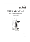
USER MANUAL SLIT LAMP MICROSCOPE Model: GR-54 Version: 1.0 Gilras LLC Version:1.0 SLIT LAMP USER MANUAL Thank you for purchasing our slit lamp microscope !The following is the description and specification of our product. General description This user manual elaborates on the relevant technical specification and operation notes of our slit lamp. Working princ iple: A beam of light attached to the slit lamp projects to the patients’ eye, which forms an optical section of the living tissue of the eye, in this way the doctor can finish the observation and examination. Slit Lamp Microscopes are used to observe the disease of the anterior structures and tissue damage of eyes. The specification of this slit lamp microscope. Microscope: Type: Magnification change: Eyepieces Angle between eyepieces: Total magnification Ratio: Pupillary adjustment: Diopter adjustment: Field of view: Slit Illumination: Slit width: Galilean-Type Five Position revolving Drum 12.5X 13º 6X, 10X, 16X, 25X, 40X 52mm~78mm ±6D 40X (∅5.5mm), 25X (∅8.5mm), 16X (∅13.5mm), 10X (∅22mm), 6X (∅34.7mm) Continuously variable from 0 to 14mm (at 14mm,slit becomes a circle ) Slit length: Continuously variable from 1mm to 14mm Aperture diameters: Lamp: ∅14mm,∅10mm,∅5mm,∅3mm∅2mm,∅1mm, ∅0.2mm 0°-180° 4 step: 5°、10°、15°、20° Heat-absorbing filter,ND filter,Red-free,Cobalt Blue 6V/20W Halogen Lamp Longitudinal movement: 90mm Lateral movement: 100mm Slit angle: Slit inclination Filters: Base Gilras LLC 2 Version:1.0 Fine Base movement: Vertical movement: Chin-Rest Vertical movement Fixation Target Power: Input voltage: Input frequency: Power Consumption: Output voltage: Light: Fixation: Dimension & Weight: Dimension Gross weight: Net weight: Working environment Temperature: Relative humidity: Air pressure: Storing environment Temperature: Relative humidity: Air pressure: Transporting environment Temperature: Relative humidity: Air pressure: SLIT LAMP USER MANUAL 15mm 30mm 80mm Red LED 220V/110V~±10% 50Hz/60Hz 30VA(max) 6V 3V 740mm × 450mm x 500mm 25Kg 24Kg +5℃~+40℃ ≤80% 800hpa~1060hpa -40℃~+55℃ ≤93% 700hpa~1060hpa -40℃~+55℃ ≤93% 700hpa~1060hpa Gilras LLC 3 Version:1.0 SLIT LAMP USER MANUAL General Requirements for Safety Please read carefully the following precautions to avoid unexpected personal injury as well as the product being damaged and other possible dangers. Precautions 1. In case there is any trouble, please first refer to the trouble-shooting guide. If it still can’t work, please contact the authorized distributor or our Repair Department. 2. Do not use this instrument in the environment prone to fire and blast or where there is much dust and with high temperature. Use it in room and simultaneously be careful to keep it clean and dry. 3. Check that all the wires are correctly and firmly connected before using. Ensure that the instrument is well grounded. 4. Please pay attention to all the ratings of the electrical connecting terminal. 5. Turn off the main power first before replacing the main bulb, flash lamp and fuse. 6. When replacing the power cable, please use the power cable in accordance with the notes in the instruction manual. 7. Don’t touch the surface of the lens and prism with hand or hard objects. 8. To prevent the instrument from falling down to floor, it should be placed on the floor where the inclination angle is less than 10° 9. Read carefully the safety and other signals on this machine in order to use the product safely. Gilras LLC 4 Version:1.0 SLIT LAMP USER MANUAL THE SAFETY MARKS, PICTURES USED IN THIS INSTRUMENT No. mark Description 1 TYPE B 2 DATE 3 4 Class I Type B The slit lamp is type I medical using equipment English form of B type 5 WEEE mark Please deal with the waste disposal produced by the machine following relevant laws and regulations. 6 CE marking 7 Part Number 8 Serial Number 9 ON 10 OFF 11 Output At the back of power supply box ,indicate outlet of the power 12 Input At the back of power supply box ,indicate input of the power 13 Fuse 14 Power At the front of power supply box, use with on and off 15 Voltage selector Change input voltage to adjust the equipment to work under appropriate voltage 16 F1AL250V Rated value and current value The marks of light dimmer Gilras LLC 5 Version:1.0 SLIT LAMP USER MANUAL Contents 1 NOMENCLATURE .......................................................................................................................................................... 7 2 ASSEMBLY ..................................................................................................................................................................... 10 3 4 2.1 CHECK LIST ............................................................................................................................................................... 10 2.2 ASSEMBLY PROCEDURE ............................................................................................................................................. 11 2.3 CHECKING PROCEDURE AFTER ASSEMBLING ............................................................................................................ 13 OPERATION PROCEDURES ..................................................................................................................................... 14 3.1 DIOPTER COMPENSATION AND P UPIL D ISTANCE ADJUSTMENT ................................................................................ 14 3.2 PATIENT POSITION AND USE OF FIXATION TARGET .................................................................................................... 15 3.3 BASE OPERATION ....................................................................................................................................................... 15 3.4 OPERATION OF ILLUMINATION UNIT ......................................................................................................................... 15 3.5 OPERATION NOTES ..................................................................................................................................................... 17 CLEANING AND DISINFECTION: ........................................................................................................................... 17 4.1 5 CLEANING.................................................................................................................................................................. 17 4.1.1 Cleaning way ........................................................................................................................................................ 17 4.1.2 Cleaning circle ..................................................................................................................................................... 18 PROTECTING AND MAINTAINING........................................................................................................................ 18 5.1 PROTECTING .............................................................................................................................................................. 18 5.2 MAINTAINING ............................................................................................................................................................ 18 5.3 REPLACING THE ILLUMINATION BULB ...................................................................................................................... 19 5.4 REPLACING THE FUSE ................................................................................................................................................ 19 5.5 CONSUMABLES .......................................................................................................................................................... 20 6. TROUBLE SHOOTING GUIDE ...................................................................................................................................... 21 APPENDIX A ........................................................................................................................................................................... 22 APPENDIX B ........................................................................................................................................................................... 22 Gilras LLC 6 Version:1.0 1 SLIT LAMP USER MANUAL Nomenclature 16 15 17 14 18 13 12 19 20 11 10 9 21 8 22 7 23 24 6 5 25 4 26 27 28 29 3 2 1 Gilras LLC 7 Version:1.0 SLIT LAMP USER MANUAL 1. Main Power Switch 2. Brightness Control Switch The brightness can be adjusted continuously. Avoid working continuously at high setting, as the service life of the bulb will be shortened. 3. Joystick Incline joystick to move the instrument slightly on the horizontal surface and rotate it to adjust the 4. 5. 6. 7. elevation of the microscope. Microscope Arm Locking Knob Lock the rotational movement of the microscopes arm. Illumination Arm Locking Knob Lock the rotational movement of the illumination arm. The indicate of relative angle between the microscope and illumination unit Mark on the angle mark ring of the illumination arm, which relates to the long mark of the microscope arm, represent the two arms’ angle when the”0” on the ring relates to the short mark at one side of the operator the right eyepiece may be blocked, and the side of the patient the left eyepiece. The mark of microscope arm Together with (6) to indicate the angle between the microscope and illumination unit 8. Magnification Select Dial Five different magnifications are provided 9. Prism Box Separate the prism box to adjust the inter papillary distance until it fit for checking 10. 12.5X Eyepieces 11. The Control Plat of Slit 12. Slit Height Control Knob 13. Filter Selection Lever and display mark The lever can choose different filters. 14. Aperture Slit Height and Display Window It will display the diameter of the slit and the aperture. 15. Lamp Cap With the function of protecting and insulating, its normal working temperature is around 51℃. 16. The plug of Lamp cap It is connected with the power of the light unit. 17. The Fixation Knob of Lamp Cap After fixing the knob, the lamp cap will not move. 18. Fixation target Make the patient stare at it, it is convenient for checking Rotate this knob to adjust the spot and the slit height. Swing the knob horizontally to revolve the slit. 19. Forehead Belt To fix the patient’s head on an appropriate position Gilras LLC 8 Version:1.0 SLIT LAMP USER MANUAL 20. Focus test rod 21. The Fixation Knob of Chin-rest Paper It is used to fix the chin-rest paper. 22. Chin-rest 23. Centering Knob of illumination unit Loosen the knob to allow the illumination light to move from the center of the vision field for indirect retro-illumination. Fastening the knob can bring the illumination light back to the center. 24. Slit Width Control Knob The slit width is continuously adjustable within the range from 0 to 14mm.The marks on the left knob stands for the approximant value of the width. 25. Illumination Inclination Lever Four inclination stops are available from 5°up to 20°. The interval between each is 5°. 26. Chin-rest Elevation Adjustment Knob Rotate the knob to adjust the elevation of the chin-rest 27. Access line and plug of the brightness control 28. Rail Cover Protect the rail surface 29. Work Table Gilras LLC 9 Version:1.0 2 2.1 SLIT LAMP USER MANUAL Assembly This section of the manual describes how to assemble the slit lamp. All parts should be taken out with great care from the packing case before assembling. Check List NO. MARK NAME QUANTITY NOTE 1 A HEAD-REST PART 1 Fig.2.1.1 2 B MICROSCOPE PART 1 Fig.2.1.2 3 C ILLUMINATION PART 1 Fig.2.1.3 4 D WORK TABLE PART 1 Fig.2.1.4 5 E RAIL COVER 1 Fig.2.1.5 6 F BREATH SHIELD 1 Fig.2.1.6 7 G INPUT POWER CABLE 1 8 H FOCUSING TEST ROD 1 9 I PROTECTING CAP 1 10 J CHIN-REST PAPER 1 11 K SCREW DRIVER 1 12 L SPARE BULB 1 13 M USER MANUAL 1 14 N PACKING LIST 1 Fig.2.1.7 Fig.2.1.8 Fig.2.1.1 Fig.2.1.2 Gilras LLC 10 Version:1.0 SLIT LAMP USER MANUAL Fig. 2.1.4 Fig. 2.1.5 Fig. 2.1.7 Fig.2.1.3 2.2 Assembly procedure 1.Open the carton,take out the tools like screw driver and spanner. 2.Check the setting on the voltage selector located on the bottom of the power box. If it doesn’t match with the input voltage, slide it to the proper position with watch screw driver. Take out the table unit check whether the power switch is in the proper position, if not use the screw driver to correct it.(caution) 3.Open the fuse holder with screw driver and take out the fuse, check and ensure that its rated value is corresponding to the mains voltage: 110V---------------------2A 220V---------------------1A It has been set to 220V, 1A before leaving Fig. 2.1.6 Fig.2.1. 8 our factory. Attention: Set the input voltage and frequency of the instrument according to that of the mains. 4.Before attaching the worktable (Fig.2.1.4)on to the power table, please screw off four M6x20mm bolts with the spanner .(Fig.2.2.1 A Team). B Team A Team Fig 2.2.1 Fig.2.2.1 5.Lift the worktable to aim its screw hole at the assembly hole of the instrument table. (Fig.2.2.2) 6.Put down the worktable, with the power Gilras LLC 11 Version:1.0 SLIT LAMP USER MANUAL panel facing the operator, refasten the bolt securely with the spanner (Fig.2.2.2). cover to the rail, remove four screws attached to the rail with the screw drive, retighten the previously removed screws. (Fig.2.2.5 and 2.2.6). Locking Screw on Base Fig.2.2.2 Rails The screw to connect with the Fig.2.2.5 electrical table 7.Connect two white adapters under table board,Turn on and press Up & Down switch to check whether the power table is normal.(Fig.2.2.3). Rail Cover Up & Down switch White Adapters Fig.2.2.3 8.Remove the four screws of B Team with the screw drive (Fig.2.1.4), take out the head-rest from carton(Fig.2.1.1), ensure the four hole on head rest aim the screw hole of B team( Fig.2.2.1 B team), retighten the previously removed screw make head-rest connect with work table .(Fig. 2.2.4) Four screws Fig.2.2.6 10.Take out the binocular tubes of microscope part (Fig.2.1.2) , match the groove on the binocular tubes with the pin on the microscope body. Fasten the fixing screw on the body to the microscope. ATTENATION:Don’t touch the objective and eyepiece when assembling. the binocular tubes Fig.2.1.2 Limit groove Fig.2.2.7 Fig.2.2.4 9.Take out the slit lamp part (Fig.2.1.3),put it on the rails of the table board, check whether the wheels can be rolled steadily on the rails. (Fig.2.2.5),place the rail Screw Limit pin Body Insert 11. Remove the breath shield fixation screw Gilras LLC 12 Version:1.0 SLIT LAMP USER MANUAL from the microscope arm, pass the removed screw though the hole of the breath shield and then screw it into the arm again (Fig.2.2.8). Fig.2.2.8 Screw B r e a t h S h i e l d of focus test rod, and the brightness should change. 19. Check the fixation target device to confirm it is lighted. Ensure it can be normally lighted (Fig.3.2.1) 20. Check whether all the moveable parts such as aperture and slit height control knob (Fig.2.3.2) filter selection lever, joy stick (Fig.2.3.4) and magnification changer lever (Fig.2.3.3) etc. could be operated freely. Fig.2.3.1 12. Insert the plug on the top of the headrest part (Fig.2.1.1) into the socked of the lamp cap (Fig.2.1.3) on the illumination part. 13. Connect the plug below the headrest part with the corresponding output socket of the power box. 14. Collect tools and spare parts, put them into the drawer under right side of table board. 2.3 Slit width control knob Fig.2.3.2 display window Filter handle Aperture knob Checking procedure after assembling 15. This instrument supplies a 3-wire cable. Please select a proper power socket as matched. Ensure that the instrument is grounded well. 16. When the main power switch of the power box is placed at ‘I’, it turns on, and ‘O’ for turn off. The main power switch should be set at the ‘O’ position before connecting the input cable with the power socket. 17. Turn on the main power switch, and the pilot lamp will be lighted. Open the light control knob to examine the brightness. The power supply signal will turn bright when power is connected(Fig.3.1.3). 18.Put on focus test rod (Fig.2.1.7), Adjust the slit width control knob and there should be facula on the black flat surface Fig.2.3.3 Magnification Joystick Fig.2.3.4 21. Turn on the light knob (Fig.3.1.3), the light should be from dark to bright. Gilras LLC 13 Version:1.0 SLIT LAMP USER MANUAL 22. After examination, turn off the main power and cover the instrument with the dust-proof cover. 3 Operation procedures 3.1 Diopter compensation and Pupil Distance adjustment ①Use of the focusing test rod The rod is supplied as one of standard accessories for confirming the microscope’s accurate adjustment. Insert it into the main shaft hole with the black flat surface facing the objective lens i.e. the direction of the operator (Fig.3.1.1 & 3.1.2). ATTENTION:After the adjustment, take out the rod. Insert rod to hole the the ③Adjustment of Diopter compensation The focus of the microscope is calibrated according to the emmetropia. If the operator is an ametropia, he should adjust the eyepiece diopter. (Fig.3.1.4). Suggest adjusting the diopter as following procedures: First, rotate the diopter adjustment ring counter clockwise until the end.(Fig.3.1.4) Second, rotate the ring clockwise until a fine slit image appears on the focusing text rod. At this time, it is also the clearest observation of the reticule in the eyepiece Adjust another eyepiece in the same way. Record the diopter value on each eyepiece for future reference. Diopter adjustment ring Fig.3.1.1 The flat faces microscope Fig.3.1.4 Fig.3.1.2 ②Brightness adjustment Switch on the main power switch and set the brightness control switch (Fig.3.1.3) at central part. Turn the slit width control knob (Fig.2.3.1) to make the slit width to be 2~3mm. Dark Fig.3.1.3 ④ Interpupillary distance adjustment Separate the prism box of the microscope with both hands to adjust the P.D. until both eyes could see the same image on the focusing test rod through the eyepieces, and at the same time a stereo vision will be obtained. When adjusting, be sure that the eyepieces are at the same level (Fig.3.1.5). Bright the box Brightness control switch prism Fig.3.1.5 Gilras LLC 14 Version:1.0 3.2 1) SLIT LAMP USER MANUAL Patient position and use of fixation target target. Turn the joystick clockwise to raise the microscope and counter clockwise to lower it. (Fig.3.3.1). Position of the patient’s head Place the patient’s chin on the chin-rest with the forehead against the forehead-rest belt. Adjust the chin-rest elevation adjustment knob below the chin-rest until the patient’s can thus align with the horizontal mark (Fig.3.2.1). 2) 3) Horizontal Fine adjustment Tilt the joystick to make the microscope move slightly on the horizontal surface. While watching though the eyepieces, tilt the joystick to aim accurately at the object for a fine image. (Fig.3.3.1) Use of the fixation target Joystick For fixing the patient’s sight, just make him look at the fixation target with the eye not to be examined. Move the lamp bar to change fixing position, so as to achieve the correct lamp position Up & Down Fig.3.3.1 4) Locking the base When finishing the adjustment, fasten the base locking screw to lock the base to prevent it from sliding. (Fig.3.3.2) Light Locking screw Belt Chin-rest Handle Fig.3.3.2 3.4 Operation of illumination unit Fig 3.2.1 1) 3.3 1) Base operation Horizontal rough adjustment Keep the joystick erect and move the base to make the microscope move on the horizontal surface to aim at the object appropriately (Fig.3.3.1) 2) Changing the slit width Turn the slit width control knob (Fig.2.3.1) and the slit width will be changed from 0mm to 14mm. The slit becomes a circle at the 14mm size. The width value is indicated approximately by the scale on the knob. (Fig.3.4.1) Show slit Vertical adjustment Rotate the joystick to adjust the microscope’s height until it aligns with the width Fig 3.4.1 Gilras LLC 15 Version:1.0 2) SLIT LAMP USER MANUAL Changing the aperture and slit height Turn the aperture and slit height control knob and 7 different circular beams of light are available at full aperture: 14,10,5,32,,1,0.2 Dia. Respectively and one continuously changing aperture With a slit image, the slit height can be changed continuously from 1 to 14mm, which is indicated though the display window (Fig.3.4.2). Center knob Fig.3.4.4 5) Oblique illumination is used for sectional or fundus examination by use of a contact lens. Press down the inclination lever so that the illumination part may incline to 20°, (5° of each division). Since the illumination part may touch the patient’s head, operate carefully (Fig.3.4.5) Window Fig.3.4.2 3) Oblique illumination Aperture knob Rotating the slit image Swing the aperture and slit height control; knob horizontally to revolve the slit image at any angle in the vertical or horizontal direction. The angle of image rotation is indicated by the rotation angle scale with small division for 5° and big division for 10°(Fig.3.4.3). Fig.3.4.3 4) Fig.3.4.5 Inclination lever Angle scale Decentering the illumination light Loosen the centering knob and swing the slit width control knob back and forth so the light spot moves away from the center of the microscope vision field. It is mainly used to examine the eyes by indirect retro-illumination. Fasten the centering knob and the slit light will return to the center of the microscope vision field (Fig.3.4.4). 6) Filter selection By shifting the selection lever four different filters can be inserted into the illumination pathway. Usually the thermal safety filter can make the patients feel comfortable. After using the other filters, we should turn back to the thermal safety. (Fig.3.4.6). Gilras LLC 16 Version:1.0 SLIT LAMP USER MANUAL bright light. 4 Cleaning and disinfection: Attention: Filter Fig.3.4.6 control handle From left to right : No Filter , Heat-absorbing filter,ND filter,Red-free, Cobalt Blue. The no filter is used for proofreading for the manufacturer. 3.5 Operation notes 1) In the course of the operation the operator should learn more about the contents of the user menu, to master the structure and function of slit lamp microscope so as to carry out the right operation and diagnosis. 2) In order to prevent unnecessary observations arising from the misuse of the judge, operators should observe clearly the different locations in the knob corresponding to a different scale and different directional marks in the process of using the SLM. 3) Operator should adjust the interpupillary distance and diopter correctly in the operating or which may lead a feeling of dizziness 4) Operator may have a feeling of dizziness in long time observing, so please adjust observing time according to personal habit. 5) There will be a branch of crack-ray irradiation in patients’ eyes, when they receiving SLM diagnosis. So if the light is too dark, it will affect the observing effect. Conversely, if the light is too bright, in a long time exposure patients’ vision might be affected. If patients feel uncomfortable, please tell the operator or take medical treatment. Therefore, please try to avoid prolonged exposure of patients’ eyes in the The replaced waste materials should be treated as industrial rubbish. 4.1 Cleaning 4.1.1 Cleaning way ① Cleaning the lens and reflecting mirror:If any dust stick on the lenses or reflecting mirror, wipe it off with soft cotton dipped with absolute alcohol. (Fig.4.1.1). Attention: Don’t wipe with hands or hard project or any corrosive detergent lest that the surface should be damaged. Objective Reflecting Mirror Fig 4.1.1 ② Cleaning the tie plate, rails and shaft:If the slide plate, rails and shaft are dirty, the vertical and horizontal movement will be unsteady. Wipe them with clean soft cloth. (Fig.4.1.2). Fig.4.1.2 Rail shaft Slide plate ③ Cleaning and sterilizing the plastic parts: Clean the plastic parts such as chin-rest bracket, forehead-rest belt with soft cloth dipped with soluble detergent or water, then sterilize with medicinal alcohol. Attention: Don’t wipe with any corrosive detergent lest that the surface Gilras LLC 17 Version:1.0 SLIT LAMP USER MANUAL should be damaged. (Fig.3.2.1). 4.1.2 Cleaning circle 1) Clean the eyepieces, objective lens and refractor: Cycle: suggested once every two months. The lenses are plated with a reflection reducing coating and reflective coating on its surface. Although the coating is hard enough, too frequent wiping will weaken it, which leads to a bad observing opt ical effect. Two month is a recommendation; if there is lots of dust on the lens, please wipe it immediately. 2) Cleaning the slide plate, rails and shaft: Cycle: suggested once a month These parts won’t get dirty in a clean environment such as hospital in one year. However, we suggest you clean them once every 6 months so that you can get a much better movement effect. 3) Cleaning the plastic parts: Cycle: suggested once a day These two parts contact with the patients directly, so please clean them timely. Please replace a new and clean chin-rest paper for each patient. 4) Cleaning the whole machine: Cycle: suggested once every two months. Fig.5.1.1 cap 5.2 Protecting and maintaining Maintaining 5.2.1. Adjust the slit width control knob If the slit width control knob is too loose, the slit width may be out of control. Fasten the locking screw on right side clockwise with a hexagon type screw driver. 1. Right knob 图 5.2.1.6 Left knob Locking screw on the right knob Fig5.2.1.1 2. Follow the steps listed below to do the adjustment. a) 5 Protection Rotate the locking screw with a hexagon type screw driver. Correct and periodical protecting and maintaining can prolong the service life of the slit lamp. The suggested maintaining circle is two months. 5.1 Protecting There are always dusts and physiological salt solution dropping into the main shaft hole of the illumination ram during the operation. Please cover the main shaft hole with the protection cap lest the instrument would be damaged. Take off the cap when the focus test rod needs to be assembled (Fig.5.1.1). Fig.5.2.1.8 b) If the knob is too loose, adjust the screw clockwise (as fig. 5.2.1.8 shows). If the knob is too tight, rotate the screw anticlockwise till the knob is comfortable to use. Gilras LLC 18 Version:1.0 SLIT LAMP USER MANUAL 5.2.2 Adjusting the inclination illumination part If the inclination mechanism illumination part is too loose, fasten on both sides of the pivot point with driver. (Fig.5.2.2.1) of the Fig.5.3.2 of the the screw the screw The bulb fixation groove Lamp base Screw Bulb Fig.5.2.2.1 5.3 Fig.5.3.3 Replacing the illumination bulb 3. Take out the old lamp part (Fig.5.3.2), replace it with a new one. The groove in the bulb fixation disc should be aligned with the flange of the lamp base; otherwise the illumination may be uneven (Fig.5.3.3). Fix the lamp part with three knobs. 4. Place the lamp cap in the original position, fix the lamp cap with the knob, insert the connecting plug. 5. Turn on the main power switch and check whether the new bulb is illuminating. Check the spot to make sure it round and no false light. (Fig.3.1.3) 1. Turn the main power switch off. (Fig.3.1.3); 2. Pull out the plug attached to the lamp house, remove out the fixation knob. Pull up the lamp cap from the illumination unit. (Fig.5.3.1& 5.3.2) Remove the lamp cap Loosen the 5.4 knobs Fig.5.3.1 Lamp part Rotate the Replacing the fuse 1. Turn off the main power switch (Fig.3.1.3), remove the power cable from the socket. (Fig.5.4.1). 2. The fuse is inserted in the fuse box which has fuse mark. Please rotate the fuse part out (Fig.5.4.1) by pressing the fuse box with a screw or a coin. One fuse is in use, the other is in spare. Please check them, if the one in use is burnt, please replace it with the spare one and then place both the two fuse parts into original place. spring piece and take out the bulb Gilras LLC 19 Version:1.0 SLIT LAMP USER MANUAL Remove the power cable Fig.5.4.1 Replace the fuse 3. The fuse specification: F1AL250V Attention: Please select the fuse of the same type, specification and rate value. 5.5 Consumables 1. Fuse: 1A/250V ……………………. 1 piece 2. Bulb: 6V20W halogen bulb The life span of the bulb is 480 hours; however, it can still work out of the time span and the brightness of the bulb might be low er. Gilras LLC 20 Version:1.0 SLIT LAMP USER MANUAL 6. Trouble shooting guide In case there is any trouble, please check according to the following table for reference. If it still cannot work, please contact the authorized distributor. Trouble Possible cause Remedy The cable isn’t connected correctly with the Connect the power cable power socket correctly No illumination The main power switch is on ‘O’ position Place the switch on ‘I’ position The plug on the power box is loosen Insert the plug firmly The plug on the lamp cap is loosen Insert the plug firmly The bulb has burnt out Change the bulb The fuse has blown Change the fuse The bulb is not assembled properly Assemble properly the bulb The filter lever is in the middle position or in the Set the filter lever to the position of gray filter correct position Slit is too dark the brightness adjustment knob is at min. the brightness adjustment knob Voltage selector is wrongly set Set the voltage selector correctly The coat of the reflecting mirror is oxidized Change mirror Too much dust on the reflecting surface Clean the surface with the brush Voltage selector id wrongly set Fuse has blown The fuse doesn’t comply with the specification the reflecting Set the voltage selector properly Replace it with a suitable fuse Slit width closes The slit width control knob is too loose automatically Adjust the tightness of the control knob Fixation bulb is off Insert the output plug firmly The output plug is loose Gilras LLC 21 Version:1.0 SLIT LAMP USER MANUAL Appendix A Electronic Circle Drawing Control plate Halogen bulb Fixation target Transformer Brightness control knob Appendix B Illustration of the board of power box: 1. Fuse box 2. Power socket 3. 110V/220V voltage selector 4. Fixation lamp socket 5. Illumination lamp socket 6. Brightness control knob socket Assembly of power supply: There is a limit groove Fig.1 Fig.2 on the socket. Please align the plug with the groove. Fig.3 Fig.4 Power box socket Gilras LLC 22 Version:1.0 1. SLIT LAMP USER MANUAL Please connect the slit lamp with power supply (as fig. 1 shows). Refer to Fig.2, take out the link wire of brightness control knob on the base and connect it to the corresponding socket on the power box. Refer to Fig.3, insert the plug of chin-rest bracket in the correct socket, and fasten it. Caution: Make sure the main power plug is not connected. 2. Check the voltage selector, this power box support working under the voltage of 110V and 220V. Please select the right voltage according to the voltage in your country. Caution: Wrong power selection may lead to damage of the instruments. 3. Open the fuse box and make sure there is a fuse assembled (as Fig,4 shows). Specification of the fuse: 110V: 220V: 2A, 1A, 125V 250V 4. Insert the main power cable and turn on the switch. Referring to the instruction of brightness control knob, the brightness of the bulb is adjustable. 5. Please do unplug all the cables connected between slit lamp and the power box when moving the slit lamp to a new place, in case there is any danger caused. Subject to change in design or specifications without advance notice version: 1.0 Gilras LLC 23