1
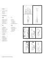
1.General EN 06 You have chosen a CrosbyIP lifting clamp. If CrosbyIP clamps are maintained as described in this manual, they will remain in optimum condition. We believe that CrosbyIP clamps are the most reliable lifting clamps available. But using reliable tools does not automatically mean that practices are reliable. The people who work with clamps play an equally important role in reliable lifting. Ensure that everyone who works with CrosbyIP lifting clamps has been instructed in the proper application of the clamps. Inter Product BV provides a 10 year warranty for its clamps. In order to benefit from this warranty programme and for more details on maintenance procedures, please consult www.crosbyip.com/warranty for more information. No changes may be made to CrosbyIP clamps. Never straighten, attempt to bend or heat treat parts. Please read and understand these instructions before using the lifting clamp. 1.2 Inspection protocols 1.1 Safety precautions Prior to every application of the clamp it is important the clamp operator inspects the clamp for proper functioning. It is not permitted to stay in the danger zone of the load. Ensure that the load remains on the ground when turning. the clamp to open under the weight of the hook, or, in the case of an unprotected crane hook, its descending from the lifting eye. When suspending the clamp directly on the secured crane hook attention must be given to ensuring that the crane hook can move freely in the lifting eye. Ensure that the crane hook and other material is protected. Remark: when handling the load, one should ensure that the load and or clamp does not encounter obstacles which could release the load on the clamps prematurely. A clamp is a device that must be clean when used. Dirt has an adverse affect on the operation and also on the reliability of the clamp. When cleaning the clamp care should be taken to ensuring that gripping surfaces are at all times clean, dry and free of oil and grease. Regular cleaning will enhance the life and reliability of the clamps. Proper instruction for the personnel is of vital importance. This will contribute to maximum reliability in the working environment. IPNM10 clamps may be applied per piece, per set or several at the same time for the lifting of plates. Because it is important that when more than 2 clamps are used each clamp receives an equal share of the load, it is recommended that an equalizing beam is used. Contact your CrosbyIP Customer Service Centre before using this clamp for plates and constructions that have a radius. Temperature: The standard lifting clamps may be used with temperatures that lie between 70 ºC (158 ºF) and -20 ºC (-4 ºF). For other temperatures contact your CrosbyIP Customer Service Centre. There are restrictions for operation in special atmospheres (e.g. high humidity, explosive, saline, acid, alkaline). Loads: For proper application of the clamp consult the load diagrams 1-2. Ensure that all attachments between lifting eye and crane are properly fitted, secured and coupled. For each lift only one plate may be transported or lifted. When the crane hook or attachment is too large and/or too heavy, use properly sized CrosbyIP 5000 stinger assembly or a chain sling with D-shackle of 75 cm. (30 inch), with a strength that corresponds to the W.L.L. of the clamp. This will, when setting the load down, prevent the hook from descending too far allowing Copyright © 2013 The Crosby Group LLC. All Rights Reserved. Attention must be paid to the following (see illustration 3 for part reference): Ensure that the plate surface with which the clamp is to come into contact is free of scale, grease, oil, paint, water, ice, moisture, dirt and coatings that might impede the contact of the gripping surface with the plate. Inspect pressure pads (W) for wear and defects. The pressure pads should be free of moisture, dirt, grease and oil. Check the body (N) en the jaw for damage, cracks or deformation (this may indicate overloading). Check the lifting eye (D) and camsegment shaft (G) for readily detectable wear and/or damage. Check the spring (M). Press when the latch lever (A) is closed on the lifting eye (D). There should be clearly apparent spring tension. The clamp should, when the lifting eye is released, return to the closed position without problems. Check whether the W.L.L. and the jaw opening stamped on the body corresponds with the load to be lifted. There is no minimum working load required. The pressure pads are the most critical parts in the clamp and require extra attention during inspection. Ensure that there are no pieces of the friction material missing as this could diminish the grip. In doubtful cases an authorised repairer should assess the clamp. Copyright © 2013 The Crosby Group LLC. All Rights Reserved. EN 07