1
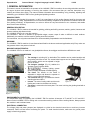
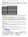
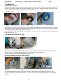
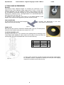
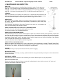
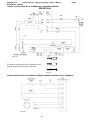
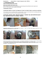
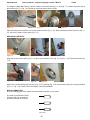
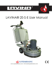
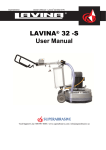
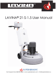
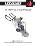
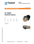
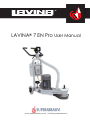
LAVINA® 7 EN Pro User Manual
www.superabrasive.com | [email protected]
Superabrasive
Owner’s Manual – Original Language Lavina® 7 EN Pro
1/2012
CONTENT
1. GENERAL INFORMATION
Preface
Manufacturer
General Description
Machine Characteristics
Lavina7N Pro Main Design
Environmental Conditions
Electrical Connection
Vacuum Connection
Technical Data
Vibrations
Sonorous Emissions
Label Data
Customer service
6. MAINTENANCE AND INSPECTION
3
3
3
3
3
3
3
4
4
4
4
4
4
First Use
Cleaning
Check Daily
Check Every 200 Working Hours
Check Every 400 Working Hours
Vacuum
Mechanical Parts
Electrical System
One phase connection
Electrical System
Lavina 7 E Pro Electrical schemes
208-240 Volt
Lavina 7 E Pro Electrical schemes
Connection Main Circuit terminals
2. SAFETY INSTRUCTIONS
Recommended Use
Prohibited Use
Preparation for Work
Protection Devices
Arrest Functions
Safe Use
Residual Risks
Before You Begin
Operating the Machine
After Work is completed
The Work Area
Personal Protective Equipment (PPE)
Operator
4
4
..5
5
5
5
5
5
5
5
5
5
5
Index of Problems and Solutions
Replacing Power Cord and Plugs
Tensioning the Belts
Replacing the Belts
Motor Connection
Fault Diagnosis Inverter Yaskawa 1000
13
14
14
15
15
16
8. WARRANTY AND RETURNS
6
6
6
6
..7
7
7
7
7
Warranty Policy
Return Policy
19
19
9. DISPOSAL
19
10. MANUFACTURER’S CONTACTS
19
4. TOOLS AND ACCESSORIES
Weights
Tool holder key
Foam plate
Floating Backer Plate
13
7. TROUBLESHOOTING
3. OPERATION
Preliminary Controls
Mounting Tools
Leveling after Mounting the tool
Adjusting Handle and Swiveling Carriage
Tool Protecting Guard
Control Board
Starting the Machine
Operating Machine
Stopping Machine
12
12
12
12
12
12
12
12
12
13
8
8
8
8
5. SPARE PARTS
Assembly and Parts Specifications
9
Assembly and parts specification main
Wheel Support
10
Assembly and parts specification main
Stair Wheel Support
10
LAVINA® 7 EN Pro Assembly and parts specification of the
electrical and control box 200-240 Volt
11
2
Superabrasive
Owner’s Manual – Original Language Lavina® 7 EN Pro
1/2012
1. GENERAL INFORMATION
This owner’s manual is intended for the operator of the LAVINA® 7 EN Pro machine, the servicing technician as well as
for anyone involved with operating or servicing the machine. We recommend that you read the instructions very
carefully and follow them strictly. The manual includes information about assembling, using, handling, adjusting and
maintaining your LAVINA® 7 EN Pro floor grinding and polishing machine.
MANUFACTURER
Superabrasive was founded 24 years ago, in 1987, as a manufacturer of high quality diamond tools for the stone and
concrete industry. Today, Superabrasive is one of the world’s leading companies in the production of diamond tools and
floor grinding machinery. At Superabrasive, we strive to deliver the very best solutions to our customers, and enable
them to work more efficiently.
GENERAL DESCRIPTION
The LAVINA® 7 EN Pro machine is intended for grinding, polishing and buffing concrete, marble, granite, limestone and
terrazzo surfaces with diamond tools.
The LAVINA® 7 EN Pro is a one-disc machine.
The LAVINA® 7 EN Pro is intended to grind/polish edges, corners, steps of stairs or difficult to reach surfaces.
Additionally, the machine could be used for grinding wood floor surfaces.
For best results, use only tools manufactured or recommended by Superabrasive and its distributors.
WARNING!
The LAVINA® 7 EN Pro machine is manufactured and fitted for the above-mentioned applications only! Every other use
may possess risks to the persons involved.
MACHINE CHARACTERISTICS
The LAVINA® 7 EN Pro is made so it can grind/polish surfaces, where bigger machines have difficulties to reach.
LAVINA® 7 EN PRO MAIN DESIGN
•
•
•
Figure 1.1
•
•
•
•
The carriage is swiveling 30º to both sides The machine can be pushed straight and
the grinding can follow a wall. The normal wheel support can be changed with a “stair”
wheel support, which can be adjusted in height
to work on stairs.
The halogen spotlight (Fig.1.2) enables the
operator to work in darker areas.
Existing lighting system
does not replace adequate overhead lighting.
The frame The handle on the frame is
adjustable in height and allows the operator to
work in a correct and safe posture.
The electrical box (fig.1.3) contains the electric
switching devices and the
Figure 1.2
inverter. The motor feeding cable and the main
feeding are located on the bottom of the box.
The motor is mounted on the base plate. The motor is driving the grinding head with a
belt system.
Figure 1.3
ENVIRONMENTAL CONDITIONS
The temperature range for operating the LAVINA® 7 EN Pro outdoors is between 41°F and 86°F or 5°C and 30°C.
Never use the LAVINA® 7 EN Pro during rain or snow when working outdoors. When working indoors, always operate
the machine in well-ventilated areas.
ELECTRICAL CONNECTION
The voltage (Volt) and power (Ampere) are displayed on a label on the electrical control box to avoid any incorrect
connection. Refer to these before connecting the power. To avoid electrical shocks, make sure the ground power
supply is functioning properly.
Superabrasive
Owner’s Manual – Original Language Lavina® 7 EN Pro
1/2012
VACUUM CONNECTION
A connection for a vacuum dust extractor is located on the handle. The LAVINA® 7 EN Pro does not include a vacuum
dust extractor. The customer must purchase the vacuum dust extractor separately. The hose of the vacuum extractor
must be Ø 50 mm and can be glided over the pipe. The vacuum dust extractor must be adapted for floor grinders and
have a minimum air displacement of 300m3/h with a negative vacuum of 21 kPa.
TECHNICAL DATA
Voltage/Hz
Amperage
Power
Tool holder rpm
Working width
Tool holder diameter
Tool diameter
Weight
Grinding pressure
Additional weight
Application
Cable length
Machine LxWxH
Packing LxWxH
LAVINA® 7 EN Pro
1 ph x 208-240 V 50/60Hz
Max 15 Amps
2.2 kW
3 hp
500-1100 rpm
175 mm
7”
165 mm
6.5”
175 mm
7”
64 kg
132 lbs
20 kg
42 lbs
max 4x2,5 kg
22 lbs
dry
17.4 m
57 ft
790x400x915 mm
31”x16” x44”
730x730x1050 mm
28,7”x28,7”x41,4”
CE-CERTIFICATION
The LAVINA® 7 EN Pro machine is designed to operate correctly in an electromagnetic atmosphere of industrial type
and is equipped with all the mechanical and electrical safety protections in conformity with the following European CEE
rules and regulations:
The LAVINA® 7 EN Pro machine complies with the Safety Directive for machines 2006/42/EC, the EMC Directive
2004/108/EC and the Low Voltage Directive 2006/95/EC.
Also complies with the norms in use BDS EN ISO 12100-1, BDS EN ISO 12100-2, BDS EN 13862, BDS EN ISO
13857, BDS EN 349, BDS EN ISO 13850, BDS EN 13732-1, BDS EN 953, BDS EN ISO 13849-1, BDS EN 1037, BDS
EN ISO 11201, BDS EN ISO 3744, BDS EN 1033:2002, BDS EN ISO 14121-1, BDS EN 60204-1, BDS EN 61000-6-4
Test results are a part of the machine’s technical information and can be sent upon a special request. The machine is
delivered with the CE mark exposed and provided with a EC declaration of conformity.
VIBRATIONS
The vibrations of the machine are measured in compliance within the standard BDS EN 1033:2002. The vibration on
the handles of the LAVINA® 7 EN Pro, working in normal conditions,.is less than 2,5 m/s² with recommended tools.
SONOROUS EMISSIONS
Sonorous emissions are measured in compliance with the standards BDS EN ISO 3744:2010 and BDS EN ISO
11201:2010. The sound pressure level at the workplace is LpA=73 dB(A). The sound power level is Lw(A)=88,5 dB(A).
However, as previously stated, the operator must wear ear protectors.
LABEL DATA
The data on the label provides the correct voltage and kW (needed for operational purposes);
Weight (needed for transportation purposes); production year and serial number (needed for maintenance purposes).
CUSTOMER SERVICE
For customer assistance and technical support contact your local distributor or contact the producer Superabrasive Ltd.
or visit us at www.superabrasive.com , where you can download a copy of this manual.
2. SAFETY INSTRUCTIONS
RECOMMENDED USE
The LAVINA® 7 EN Pro machine is designed and manufactured
to grind and polish concrete, terrazzo and natural stone floors. It
can be used for renovations as well as for polishing. The
machine is designed for dry use. Use a vacuum of appropriate
size. For more information, please refer to the chapter on
handling the vacuum connection.
4
PROHIBITED USE
The machine MUST NOT be used:
•
For applications different from the ones stated in the
General Description chapter.
•
For not-suitable materials.
•
In environments which:
•
Possess risks of explosion
Superabrasive
•
•
•
•
Owner’s Manual – Original Language Lavina® 7 EN Pro
Possess high concentration of powders or oil substances in
the air
Possess risks of fire
Feature inclement conditions.
Possess electromagnetic radiation.
PREPARATION
FOR
WORK
Make sure that:
•
You have closed the work area, so that no person
unfamiliar with operating the machine can enter the area
•
The tool plate and tools are adjusted to the machine
properly
•
There are no missing parts of the machine
•
The machine is in upright working position
•
The protection devices are working properly.
•
The electrical cable is free to move and follow the machine
easily. In order to keep the electrical cable from being
damaged, no vehicle should cross the zone where electrical
cables are situated.
PROTECTION DEVICES
•
The machine is equipped with several protection devices
including the following:
•
An emergency stop button
•
A protection skirt and a hood for protecting the tool plates.
•
These devices protect the operator and/or others persons
from potential injuries. Do not remove them. On contrary,
before using the machine, please ensure that all protection
devices are mounted and function properly.
ARREST FUNCTIONS
Functions of arresting of the machine are following:
•
Button to stop the motor (category 1)
•
Emergency button (category 1)
•
•
•
•
•
•
•
•
1/2012
Ground wire system of the power supply must be also
inspected.
Perform general daily inspections of the machine and
inspect the machine before each use.
Always inspect the safety devices:
The emergency break must be clear and working
The tool protector must be working
The machine must be clean
Never operate the machine in the rain!
Confirm that there are no missing parts especially after
transportation, repair or maintenance.
OPERATING MACHINE
•
When operating the LAVINA® 7 EN Pro, make certain that
there is no one, but you around the machine.
•
Never leave the machine unattended while working.
•
The electrical cable must move freely and must be damagefree.
•
Check if the floor, you work on, is not too uneven. If this is
the case, it may damage the machine.
AFTER WORK IS COMPLETED
•
•
•
Clean the machine and its surroundings properly
Unplug the machine and wind up the electrical cable
Store the machine in a safe place
THE WORK AREA
•
Make certain that people or vehicles do not enter the work
area.
•
Avoid cables and hoses being in the way.
•
Always check the floor for debris
PERSONAL PROTECTIVE EQUIPMENT (PPE)
SAFE USE
•
The LAVINA® 7 EN Pro is designed to eliminate all risks
correlated with its use. However, it is not possible to
eliminate the risks of an eventual accident with the
machine. Unskilled or uninstructed operator may cause
correlated residual risks. Such risks are:
• Position Risks due to operator’s incorrect working
position
• Tangling up Risks
due
to
wearing
inappropriate working clothes
• Training Risks due to lack of operational training
NOTE: In order to reduce all consequences of the abovementioned risks, we advise that machine operators will follow
the instructions in the manual at all times.
RESIDUAL RISKS
•
During the normal operating and maintenance cycles, the
operator is exposed to few residual risks, which cannot be
eliminated due to the nature of the operations.
BEFORE YOU BEGIN
•
Working area must be clear from any debris or objects.
•
A first-time operator must always read the manual and pay
attention to all safety instructions.
•
All electric connections and cables must be inspected for
potential damages.
5
•
•
•
•
•
Always wear safety shoes when working with the machine.
Always wear ear protectors when working with the machine.
All personnel in the immediate work area must wear safety
glasses with side shields.
Always wear safety gloves when changing the tools.
Always wear clothes suitable for the work environment.
OPERATOR
•
The LAVINA® 7 EN Pro machine.
•
The operator must know the machine’s work environment.
•
Only one operator at a time can work with the machine.
•
The operator must be properly trained and well instructed
prior operating the machine.
•
The operator must understand all the instructions in this
manual.
•
The operator must understand and interpret all the drawings
and designs in manual.
•
The operator must know all sanitation and safety regulations
pertaining to the operation of
•
The operator must have floor grinding experience.
•
The operator must know what to do in case of emergency.
•
The operator must have an adequate technical knowledge
and preparation.
Superabrasive
Owner’s Manual – Original Language Lavina® 7 EN Pro
1/2012
3. OPERATION
PRELIMINARY CONTROLS
Inspect the working area as explained in the safety instructions. For dry use connect the vacuum extractor and ensure
that the vacuum hose is clear and it will follow the machine easily. Plug in the machine and make sure that the power
cord is free to follow the working direction of the LAVINA® 7 EN Pro.
MOUNTING TOOLS
Figure 3.1
Figure 3.3
Figure 3.2
Mount the tools only after ensuring that there is enough diamond bond material left. Be sure that the plates are always
clean before mounting. Unplug the machine before dismounting or mounting the tools. Always use the tool holder key,
turn the butterfly in the middle to ensure the tool (Fig.3.1).
Diamond tools with Velcro are attached on the foam plate of 7 inch (Fig. 3.3). The foam plate (is mounted the same way
as the other tools (Fig. 3.2).
LEVELING AFTER MOUNTING THE TOOL
Figure 3.4
Figure 3.5
To ensure the tool works flat on the floor, the machine has to be leveled. On top of the base plate is mounted a round
water level (Fig. 3.5). Attention using the water level should be done only on a flat surface.
To level the machine, turn the knob between the wheels (Fig. 3.4).
ADJUSTING HANDLE AND SWIVELLING CARRIAGE
Figure 3.6
Figure 3.8
Figure 3.7
For adjusting the handle in height, turn loose the swivel bolt, after finding the right position lock it back (Fig. 3.6).
Find the right angle of working the machine (Fig. 3.7), swivel left or right the carriage by unblocking the turning wheel
(Fig. 3.8).
6
Superabrasive
Owner’s Manual – Original Language Lavina® 7 EN Pro
1/2012
TOOL PROTECTING GUARD
Turn the tool protecting guard in the preferredposition. Adjust the height
according the toolwhile mounting on the “Velcro” strip. (Fig. 3.9)
Figure 3.9
THE CONTROL BOARD
1.
2.
3.
4.
5.
6.
7.
Lamp jack
plug out/in the lamp when needed
Reset button
resets the alarm of the inverter
Power led
lights green when the power is on
Emergency button used in Emergency situations for stopping the motor
ON button
starts motor
OFF button
Stops motor
Potentiometer
changes the RPM of the grinding plates,
from 500-1100 rpm
Figure 3.10
STARTING THE MACHINE
First, follow the directions in chapter Safety Devices and Safety Instructions. Next, pull the emergency stop (Fig. 3.10 4)
to ensure that the machine is in working condition. Check the potentiometer (Fig. 3.10 7) and ensure that it is set at the
working speed. Switch on the vacuum unit. Finally, hold the machine firmly and push the start button (Fig. 3.10 5).
OPERATING THE MACHINE
Guide the machine in straight lines across the floor, and with each new line overlap a little bit of the previously
completed surface. Work at a constant speed allowing the tools time to work at a speed appropriate for the tools’ grit
size. Avoid vibrations. Do not stop the LAVINA® 7 EN Pro machine in one spot while the tools are still working because
they will leave marks on the floor surface. Check the floor surface periodically to ensure that dust is not accumulating on
the surface, also check regularly if your vacuum works properly.
STOPPING THE MACHINE
The stopping of the machine must be done gradually until the motor stops. Do not stop moving the machine before
arresting the motor as the tools could damage the surface. Switch off with the off button (Fig. 3.10 6). Use the
Emergency button (Fig. 3.10 4) only in emergency or use it to switch the power totally off.
Remember not to hold the machine in one spot before turning off the motor.
7
Superabrasive
Owner’s Manual – Original Language Lavina® 7 EN Pro
1/2012
4. TOOLS AND ACCESSORIES
WEIGHTS
Superabrasive offers additional weights for increasing the productivity of the
machine (Fig.4). Each additional weight weighs about 5.5 lbs or 2,5 kg. Each
individual application, type and condition of surface, power capacity of the outlet,
etc. will determine the number of weights you can use without tripping a breaker,
Although wit a maximum of four. The weight stacks on to central shaft above the
toolts around the outer bowl (Fig.4.1).
The additional weight depends on the tools; it is not always possible to add
weights. Some tools work too aggressively and the machine can stop.
TOOL HOLDER KEY
The tool holder key (Fig. 4.2) is used for adjusting,
Always use the key for mounting.
Figure 4.1
mounting and dismounting of the tools.
Item number is A03.00.00.00
Figure 4.2
FOAM PLATE
Diamond tools with Velcro are mounted on thefoam plate 7“(Fig.4.3). The foam plate is
mounted on the flexible backer plate. Item number is LV-7-FP
FLOATING BACKER PLATE
A floating backer plate (Fig. 4.3) is mounted on the grinding head. Its advantage is that
it has elastic shock absorbers, which enable the tool plate to float and follow the
surface profile. A tool can be attached with use of the tool holder key.
Figure 4.3
Figure 4.3
Item Number
Description
Qty.
1
A01/00.00.02
Sealer Front
1
2
М6х20DIN7991
Screw
4
3
A01/00.00.01
Shock Absorber
4
To order any parts, customer has to provide the machine model and serial number. Without
this information, customer is responsible for ordering the correct part, and no shipping
charges will be refunded if the part ordered is wrong.
8
Superabrasive
Owner’s Manual – Original Language Lavina® 7 EN Pro
1/2012
5. SPARE PARTS
LAVINA® 7 EN PRO ASSEMBLY AND PARTS SPECIFICATION (FIG. 5.1)
Figure 5.1
To order any parts, customer has to provide the machine model and serial number. Without this information, customer is responsible for
ordering the correct part, and no shipping charges will be refunded if the part ordered is wrong.
9
Superabrasive
№
1
1а
1b
2
3
4
5
6
7
8
9
10
11
12
13
14
15
16
16а
17
18
19
20
21
22
23
24
25
26
27
28
29
Owner’s Manual – Original Language Lavina® 7 EN Pro
Item Number
L7NP-00.00.00.10
L7NP-00.00.00.11
L7NP-00.00.00.12
LC-57-08.00.00.00
L25SPS-02.00.00.18
L25SPS-01.00.00.00
А58165
LC-7-05.00.00.00
A58194
L7NP-05.00.00.00
М8DIN125А
М8DIN7980
М10DIN933
L7P-03.00.00.00
М5DIN127B
М5x12DIN912
LC-57-00.00.00.49
L7P-02.00.00.00
L7P-06.00.00.00
L7NP-01.02.00.00-03
L7P-01.00.00.01
6004
М6x12DIN912
М6DIN7980
LC-57-00.00.00.57
М5x10DIN84A
М5DIN6798A
М10DIN125А
М10DIN439
М10x50DIN933
М10DIN934
LC-57-03.00.00.00
Description
Electro Motor
Fan Cover
Fan
Air Duct Connection
Nut
Lamp Holder Unit
Swivel Bolt
Handle Assembly
Swivel Bolt
Control Box
Washer
Spring Washer
Bolt
Leveling Wheel Assembly
Spring Washer
Screw
Swivel Bolt
Normal Wheel Support
Stair Wheel Support
Back Housing Ass.
Roller Assembly Cap
Roller Assembly
Screw
Spring Washer
Bottom Cover
Screw
Washer
Washer
Nut
Bolt
Nut
Vacuum Port
№
30
31
32
33
34
35
36
37
38
39
40
41
42
43
44
45
46
47
48
49
50
51
52
53
54
55
56
57
58
59
60
61
62
Qty.
1
1
1
1
2
1
1
1
1
1
4
8
4
1
3
3
2
1
1
1
2
2
6
6
1
14
18
5
1
1
5
1
Item Number
LC-57-00.00.00.33
А01/00.00.00
LC-57-00.00.00.38
LC-57-00.00.00.36
М5x20DIN912
LC-57-00.00.00.40
LC-57-00.10.00.00
М8x30DIN912
LC-57-00.00.00.41
L7P-01.01.00.00
LC-57-00.00.00.37
LC-57-11.00.00.00
LC-57-00.00.00.51
SPZ934
LC-57-00.00.00.43
LC-57-00.00.00.47
LC-57-00.00.00.44
LC-57-02.00.00.00
LC-57-12.00.00.00
LC-57-00.11.00.00
L7P-04.00.00.00
DF30
М3x8DIN84A
D40L860
М10x30DIN912
М8DIN934
М8DIN127B
М8DIN433
М10DIN127B
LC-57-00.00.00.29
L25SPS-00.00.00.15
М6x20DIN84A
L7P-00.00.00.02
1/2012
Description
Guard
Floating Back Up Plate
Pin
Shaft Extension
Bolt
Cap
Cover
Bolt
Insert
Front Housing
Bushing
Spindle Housing
Nut
Belt
Grinding Pulley
Washer
Nut
Top Cover Assembly
Guide Assembly
Weights Holder
Motor Base Assembly
Water level
Screw
Air Duct Hose
Bolt
Nut
Spring Washer
Washer
Spring Washer
Motor Pulley
Washer
Screw
Knob
Qty.
1
1
4
1
4
1
1
4
1
1
1
1
4
2
1
1
1
1
1
1
1
1
3
1
4
4
4
4
4
1
1
1
1
LAVINA® 7 EN PRO ASSEMBLY AND PARTS SPECIFICATION (FIG. 5.2)
WHEEL SUPPORT
№
Item Number
Description
Qty.
1
L7P-02.01.00.00
Wheel Support Frame
1
2
М5x16DIN7991
Screw
2
3
LC-7Р-09.00.00.03
Washer
2
4
VPA175-8K
Wheel
2
Figure 5.2
LAVINA® 7 EN PRO ASSEMBLY AND PARTS SPECIFICATION (FIG. 5.3)
STAIR WHEEL SUPPORT
№
Item Number
Description
Qty.
1
L7P-06.01.00.00
Stair Wheel Support Frame
1
2
L7P-06.02.00.00
Wheel assembly
2
3
L7P-06.00.00.03
Clamp
2
4
М12DIN125А
Washer
2
5
М12х19А580-80
Swivel bolt
2
Figure 5.3
To order any parts, customer has to provide the machine model and serial number. Without this information, customer is responsible for
ordering the correct part, and no shipping charges will be refunded if the part ordered is wrong.
10
Superabrasive
Owner’s Manual – Original Language Lavina® 7 EN Pro
1/2012
LAVINA® 7 EN PRO ASSEMBLY AND PARTS SPECIFICATION OF THE CONTROL BOX (FIG. 5.4)
208-240 Volt
Figure 5.4
№
Item Number
Description
Qty.
1
L25SPS-01.00.00.00
Lamp Unit Incl. Cable and Plug
1
2
0.625x1/2
Cap
3
CM-3025/200
Metal Box
4
MM3025
Plate
1
5
230/12/24V/50/46/4VA
Transformer
1
6
NB1-63/1P/4A
Circuit Breaker
1
7
20MM
Rail
1
8
3G3MJVPFI-1020-E
Filter
1
9
CIMRUVBA0012FAA
Inverter Yaskawa (V1000)
1
10
M20x1.5
Cable Gland
1
11
HO7BQ-F3x2.5—17.4M
Cable
1
12
PG16
Cable Gland
13
HO7BQ-F4x2.5-0.7
Cable
14
SZ1RV1207
Potentiometer
1
15
ZBPO
Cap
1
16
NP2-BA31
Button
3
17
XB7-ES542.P
Emergency Stop
1
18
ND16-22-CS/2GREEN
Led Green
1
19
NP2-BA42
Button
1
20
XB4BW36B5
Button
1
21
D9.3
Female Jack
1
To order any parts, customer has to provide the machine model and serial number. Without this information, customer is responsible for
ordering the correct part, and no shipping charges will be refunded if the part ordered is wrong.
11
Superabrasive
Owner’s Manual – Original Language Lavina® 7 EN Pro
1/2012
6. MAINTENANCE AND INSPECTION
FIRST USE
Before first use please mount the Levelling Wheel Assembly in place. Put the transverse
shaft (Fig. 6.1 4) in position on top of the back housing assembly (Fig. 5.1 17). Turn the
shaft (Fig. 6.1 3) from under the back housing assembly (Fig. 5.1 17) through the transverse
shaft (Fig. 6.1 4) mount the turning wheel (Fig. 6.1 6) and secure with screw (Fig. 6.1 5).
CLEANING
Keep your machine clean. Cleaning the machine on a regular basis will help detect and
solve potential problems before they cause damage to the machine. Most importantly,
check and clean the tool plate connections, power cord and plugs, vacuum hoses.
CHECK DAILY
After operating the LAVINA® 7 EN Pro, the operator should conduct a visual inspection of
the machine. Any defect should be solved immediately. Pay attention to power cords, plugs
and vacuum hoses.
Shock absorbers A01/00.00.01 (See page Floating backer plate) are consumables and
have to be checked daily and replaced if needed.
CHECK AND REPLACE AFTER THE FIRST 15 WORKING HOURS
Check the belt tension after 15 hours working with the machine.
For the correct tension, see TROUBLESHOOTING.
Figure 6.1
CHECK EVERY 200 WORKING HOURS
Every 200 working hours, the operator should inspect all parts of the machine carefully. Most importantly, inspect and
clean the tool plate connections, power cord and plugs, vacuum. Check the guard assembly. Make certain the wheels
are clean and rotate properly. Inspect the control buttons. If there are defective control parts, they should be replaced
immediately. Replace worn vacuum- and water hoses. Carefully inspect the seal rings and bearings of the grinding
units, and replace any showing signs of excessive wear.
For more information, refer to chapter troubleshooting below.
CHECK EVERY 400 WORKING HOURS
Besides the checks of 200 working hours, open up the bottom cover like described in chapter “TROUBLE SHOOTING
REPLACING BELT Check if sealers, belt and bearings are in good condition, change if needed. Beware by tensioning
the belt not to “over tension”; the belt will never regain his original tension.
VACUUM
As stated previously, frequently check hoses and other parts for clogging.
MECHANICAL PARTS
Parts such as the belt, seal rings, cap rings, spiders and buffers and guard assembly are subject to wear and should be
replaced as needed.
ELECTRICAL SYSTEM
Dust should not enter the control box as it will destroy the contacts. Remove (blow out) any dust present.
ONE PHASE CONNECTION
Please note: the power cable has 3 wires, one ground is yellow/green the other 2 other colors are “hot” wires and
should be connected to the phases. (Fig. 6.2)
Figure 6.2
12
Superabrasive
Owner’s Manual – Original Language Lavina® 7 EN Pro
ELECTRICAL SYSTEM
LAVINA® 7 EN PRO ELECTRICAL SCHEMES WITH YASKAWA INVERTER
1/2012
208-240 Volt
Figure 6.3
The motor is connected in “Delta” (triangle) 230 Volt,
reminder for the wire connection of the motor.
Figure 6.4
LAVINA 20 PRO ELECTRICAL SCHEMES YASKAWA CONNECTION MAIN CIRCUIT TERMINALS
Figure 6.5
Figure 6.5
13
Superabrasive
Owner’s Manual – Original Language Lavina® 7 EN Pro
1/2012
7. TROUBLESHOOTING
INDEX OF PROBLEMS AND SOLUTIONS
REPLACING POWER CORD AND PLUGS
When replacing the power cord or plugs always use cords and plugs with specifications as the original ones.
Never use lower quality or different type cord and plugs.
TENSIONING THE BELTS
PLEASE MAKE SURE YOU CHECK THE TENSION OF THE BELT AFTER THE FIRST 15 HOURS OF OPERATION
If the operator notices, the grinding spindle is turning irregular or noisy or in the worse case, the grinding spindle does
not turn although the motor turns. It is recommended to check the belts.
ATTENTION: NEVER “OVER” TENSION THE BELT, THE BELT WILL BE DISTROYED AND IT
WILL NEVER RECOVER ITS ORIGINAL TENSION
Figure 7.1
Figure 7.3
Figure 7.2
Unscrew the vacuum port (Fig. 5.1 29) and pull it out (Fig. 7.1, Fig. 7.2). Take off the weight holder (Fig. 5.1 49)
together with the guide (Fig. 5.1 48) (Fig. 7.3).
Figure 7.4
Figure 7.6
Figure 7.5
Unscrew the bolts (Fig. 7.4) of the top cover (Fig. 5.1 47) and take it away (Fig. 7.5).Check the tension of the belts (Fig.
7.6). If the belts are damages or broken; see next chapter “Replacing the Belts” how to replace them.
The Static Belt Tension should be 250 N with a new belt, only 200 N with a used one. It is recommended to use an
OPTIKRIK 1 Tension Gauge (Fig. 7.6).
Figure 7.7
Figure 7.8
Figure 7.9
14
Superabrasive
Owner’s Manual – Original Language Lavina® 7 EN Pro
1/2012
To change the Static Belt Tension, lose the 4 bolts on the motor base (Fig. 5.1 50) (Fig. 7.7). Unsecure the two nuts of
the tensioner (Fig. 7.8, Fig. 7.9) Tension by moving the motor closer or wider.
Figure 7.10
Figure 7.11
Figure 7.12
After tensioning secure back the nuts on the tensioner device (Fig. 7.10). When mounting back the top cover (Fig. 5.1
47), see to it the sealer is still in place (Fig. 7.11).
REPLACING THE BELTS
Figure 7.13
Figure 7.14
Figure 7.15
Open the tension device totally (Fig. 7.13). Open up the bottom cover (Fig. 5.1 22) (Fig. 7.14). Remove the belts (Fig.
7.15).
Figure 7.16
Figure 7.17
Figure 7.18
Slide in the new belt through the top cover (Fig. 5.1 47) opening (Fig. 7.16). Put the belt in place by turning the pulleys
(Fig. 7.17, Fig. 7.18). Tension like in the chapter “Tensioning the Belts”
MOTOR CONNECTION
In case of changing the motor, please check the cable connection to your motor.
The motor is connected in “Delta”
(Triangle) 230 Volt, reminder for
the wire connection of the motor.
Figure 8.36
15
Superabrasive
Owner’s Manual – Original Language Lavina® 7 EN Pro
FAULT DIAGNOSIS INVERTER YASKAWA V1000
Pages are referring to
Yaskawa Electric SIEP C710606 18A YASKAWA AC Drive – V1000 Technical Manual
16
1/2012
Superabrasive
Owner’s Manual – Original Language Lavina® 7 EN Pro
17
1/2012
Superabrasive
Owner’s Manual – Original Language Lavina® 7 EN Pro
18
1/2012
Superabrasive
Owner’s Manual – Original Language Lavina® 7 EN Pro
1/2012
8. WARRANTY AND RETURNS
Warranty Policy for LAVINA® 7 EN Pro
Superabrasive Ltd. guarantees that the original purchaser of the LAVINA® 7 EN Pro machine will be covered against
defects in material and workmanship for a period of 2 years from the date of delivery or 500 hours of use whichever
comes first.
The following conditions pertain to this warranty:
• Applies only to the original owner and it is not transferable.
• Machine must not be dismantled and tampered with in any way.
• Covered components proven defective will be repaired or replaced at no charge. Covered components
include motors, bearings and switches.
• This warranty does not apply to any repair arising from misuse, neglect or abuse, or to repair of proprietary
parts.
• This warranty does not apply to products with aftermarket alterations, changes, or modifications.
• This warranty is in lieu of and excludes every condition of warranty not herein expressly set out and all
liability for any form of consequential loss or damage is hereby expressly excluded.
• This warranty is limited to repair or replacement of covered components and reasonable labor expenses.
• All warranty returns must be shipped freight prepaid.
The above warranty conditions may be changed only by Superabrasive. Superabrasive reserves the right to inspect and
make a final decision on any machine returned under this warranty. This warranty applies to new, used and demo
machines.
Superabrasive does not authorize any person or representative to make any other warranty or to assume for us any
liability in connection with the sale and operation of our products.
RETURN POLICY FOR LAVINA® 7 EN PRO
LAVINA® 7 EN Pro machines may be returned, subject to the following terms:
In no case, a machine is to be returned to Superabrasive Ltd. for credit or repair without prior authorization. Please
contact Superabrasive Ltd. or your local distributor for an authorization and issuance of a return authorization number.
This number along with the serial number of the machine must be included on all packages and correspondence.
Machines returned without prior authorization will remain property of the sender and Superabrasive Ltd. will not be
responsible for these.
9. DISPOSAL
If your machine after time is not usable or needs to be replaced, send the machine back to Superabrasive or a local
distributor, where a professional disposal complying with the environment laws and directives is guaranteed.
10. MANUFACTURER’S CONTACTS
If you need to contact Superabrasive Ltd. with technical support questions, below is the contact information.
Address;
Superabrasive Ltd.
Rabotnicheska 2A
BG-6140 Krun
Bulgaria
Email:
[email protected]
Tel.:
+359 431 6 44 77
Fax:
+359 431 6 44 66
Website:
www.superabrasive.com
19