1
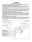
LAVINA® 21-S-1.5 User Manual
Tech Support Line: 800-987-8403 | www.superabrasive.com | [email protected]
Superabrasive
User Manual
Original Language
Lavina® 21-S-1.5
1/2013
CONTENT
1. GENERAL INFORMATION
Preface
Manufacturer
General Description
Machine Characteristic
Lavina 21 Main Design
Technical Data
Environmental Conditions
Electrical Connection
Vacuum Connection
Vibrations
Sonorous Emissions
Label Data
Customer service
2. SAFETY INSTRUCTIONS
Recommended Use
Prohibited Use
Preparation for Work
Protection Devices
Arrest Functions
Safe Use
Residual Risks
Before You Begin
Operating the Machine
After Work is completed
The Work Area
Personal Protective Equipment
(PPE)
Operator
3. HANDLING AND
TRANSPORTATION
Adjusting the column angle
3
3
3
3
3
4
4
4
4
4
.4
4
4
5
5
5
5
5
5
5
5
5
5
5
5
6
6
Adjusting the handle
Preparing the machine for
transportation
Storage
6
7
7
4. OPERATION
Preliminary Controls
Mounting Tool holders
Mounting Tools
Plug and cable
Control Board
Starting the Machine
Operating Machine
Stopping Machine
7
7
8
8
8
8
8
8
5. ACCESSORIES
Weights
9
6. POPULAR TOOLS AND
APPLICATIONS
Applications
Tools
10
10
7. EXPLOSION
General explosion
Explosion of the carriage
Explosion of the main head
Explosion of the bottom cover
Explosion of the driving belts
Explosion of the pulleys
Explosion of the base plate
Explosion of the disc assembly
14
14
15
15
15
15
16
16
8. MAINTENANCE AND
INSPECTION
Cleaning
2
17
Check Daily
Check and replace every 200
Working Hours
Check and replace every 500
Working Hours
Vacuum
Water Leaks
Mechanical Parts
Electrical System
Electrical Schemes
14
17
17
17
17
17
17
17
9. TROUBLESHOOTING
Index of Problems and Solutions22
Replacing of Plugs
22
Replacing of Pins of the
Pulley units
22
Replacing of V ring
22
Preparing for replacing belts
23
Dismounting belts
24
Changing of the Pulley units
24
Mounting of belts
25
Machine stops working
25
10. WARRANTY AND RETURNS
Warranty Policy for Lavina 21 26
Return Policy for Lavina 21
26
11. DISPOSAL
26
12. MANUFACTURER’S
CONTACTS
26
13. SPAREPARTS
30
Superabrasive
User Manual
Original Language
Lavina® 21-S-1.5
1/2013
1. GENERAL INFORMATION
This owner’s manual is intended for the operator of the Lavina 21 machine, the servicing technician as well as for
anyone involved with operating or servicing the machine. We recommend that you read the instructions very carefully
and follow them strictly. The manual includes information about assembling, using, handling, adjusting and maintaining
your Lavina 21 floor grinding and polishing machine.
MANUFACTURER
Superabrasive was founded in 1987, as a manufacturer of high quality diamond tools for the stone and concrete
industry. Today, Superabrasive is one of the world’s leading companies in the production of diamond tools and floor
grinding machinery. At Superabrasive, we strive to deliver the very best solutions to our customers, and enable them to
work more efficiently.
GENERAL DESCRIPTION
The Lavina 21 machine is intended for grinding, polishing, and buffing concrete, marble, granite, limestone, and
terrazzo surfaces with diamond tools.
The Lavina 21 is a three-disc machine, which can be used dry as well as wet.
For best results, use only tools manufactured or recommended by Superabrasive and its distributors. Additionally, the
machine could be used for grinding wood floor surfaces.
WARNING!
The Lavina 21 machine is manufactured and fitted for the above-mentioned applications only! Every other use may
possess risks to the persons involved.
MACHINE CHARACTERISTICS
The Lavina 21 is made of two main component sections:
LAVINA 21 MAIN DESIGN
•
•
•
•
•
•
•
The two main component sections, the carriage (1) and main head (2).
The handle on the frame is adjustable in height and allows the operator
to work in a correct and safe posture.
The controls are positioned on top of the frame.
The electrical box (fig.1.2) contains the electric
switching devices. The motor feeding cable and
the main feeding cable are plugged in the socket
located on the bottom of the frame.
• The water tank
Figure 1.1
The motor, mounted on the base plate, is driving the three heads with a belt
system. The planetary motion derives from the friction between the tools Figure 1.2
and the floor, which is allowing the tools to spin in either clockwise or
counterclockwise direction. The design ensures that the tools will not force themselves against the resistance of
the floor surface. Instead, the machine will alternate directions to accommodate to a “high spot” or a “low spot”
imperfections in the floor without causing damage to the floor or the machine.
The self-leveling Guard is designed to have contact with the surface. Anytime, no matter the height of the tool
used.
“Quickchange” tool holder is designed to hold the tools with “Quickchange” connection (Fig.1.3) is mounted
on each of the three grinding heads with pins.
• The “Foam” tool holder is designed to hold tools
with Velcro connection. It is mounted on each of the
three grinding heads with pins. The Velcro makes
changing of tools fast and easy.(Fig.1.4)
Figure 1.4
Figure 1.3
3
Superabrasive
User Manual
Original Language
TECHNICAL DATA
Lavina® 21-S-1.5
1/2013
Lavina 21-S-1,5
Voltage/Hz
1 ph x 115 V 60Hz
Amperage
Max 16 Amps
Power
1,8 kW
Tool holder rpm
2.45 hp
300 - 700 rpm
Working width
508 mm
20”
Tool holder diameter
3 x 197 mm
3 x 7.75”
Tool diameter
3 x 200 mm
3 x 8”
Weight
98 kg
216 lbs
Grinding pressure
59 kg
130 lbs
Additional weight
max 2x8 kg
max 2x8 kg
Application
Vacuum hose port
Ø 50,8 mm
2”
Water tank capacity
20 l
5.2 gal
Water feed
Peripheral
Machine LxWxH
1500x540x1070 mm
59.1”x21.3” x42”
Packing pallet LxWxH
1100x750x1400 mm
43.3”x29.5”x55”
Packing crate LxWxH
1100x750x780 mm
43.3”x29.5”x30.7”
ENVIRONMENTAL CONDITIONS
The temperature range for operating the Lavina 21 outdoors is between 41°F and 86°F or 5°C and 30°C. Never use the
Lavina 21 during rain or snow when working outdoors. When working indoors, always operate the machine in wellventilated areas.
ELECTRICAL CONNECTION
The voltage (Volt) and power (Ampere) are displayed on a label on the electrical control box to avoid any incorrect
connection. Refer to these before connecting the power. To avoid electrical shocks, make sure the ground power
supply is functioning properly.
VACUUM CONNECTION
A connection for a vacuum dust extractor is located on the carriage. The Lavina® S machine does not include a
vacuum dust extractor. The customer must purchase the vacuum dust extractor separately. The hose of the vacuum
extractor must be Ø 50.8 mm and can be glided over the pipe. The vacuum dust extractor must be adapted for floor
grinders and have a minimum air displacement of 320m3/h with a negative vacuum of 21 kPa .
VIBRATIONS
The vibrations of the machine are within the limits of directives and harmonized standards from the European Union
when the Lavina® S is operated with the recommended tools and in normal conditions.
SONOROUS EMISSIONS
The sonorous emissions are within the limits of directives and harmonized standards from the European Union when
the Lavina® S is operated with the recommended tools and in normal conditions. However, as previously stated, the
operator must wear ear protectors.
LABEL DATA
The data on the label provides the correct Voltage and kW (needed for operational purposes);
Weight (needed for transportation purposes); production year and serial number (needed for maintenance purposes).
CUSTOMER SERVICE
For customer assistance and technical support call your local distributor or call Superabrasive Inc. at
1-800-987-8403 or visit us at: www.superabrasive.com , where you can download a copy of this manual.
4
Superabrasive
User Manual
Original Language
Lavina® 21-S-1.5
1/2013
2. SAFETY INSTRUCTIONS
RECOMMENDED USE
The Lavina 21 machine is designed and manufactured to grind
and polish concrete, terrazzo and natural stone floors. It can be
used for renovations as well as for polishing. The machine is
designed for dry or wet use. When using it dry, use a vacuum of
appropriate size. For more information, please refer to the
chapter on handling the vacuum connection.
PROHIBITED USE
The machine MUST NOT be used:
•
For applications different from the ones stated in the
General Description chapter.
•
For not-suitable materials.
•
In environments which:
•
Possess risks of explosion
•
Possess high concentration of powders or oil substances in
the air
•
Possess risks of fire
•
Feature inclement conditions.
•
Possess electromagnetic radiation.
•
The machine should be not connected to electricity when
changing the tools
PREPARATION FOR WORK
Make sure that:
•
You have closed the work area, so that no person
unfamiliar with operating the machine can enter the area
•
The tool plate and tools are adjusted to the machine
properly
•
There are no missing parts of the machine
•
The machine is in upright working position
•
The protection devices are working properly.
•
The electrical cable is free to move and follow the machine
easily. In order to keep the electrical cable from being
damaged, no vehicle should cross the zone where electrical
cables are situated.
PROTECTION DEVICES
•
The machine is equipped with several protection devices
including the following:
•
An emergency stop button
•
A protection skirt and a hood for protecting the tool plates.
•
These devices protect the operator and/or others persons
from potential injuries. Do not remove them. On contrary,
before using the machine, please ensure that all protection
devices are mounted and function properly.
ARREST FUNCTIONS
Functions of arresting of the machine are following:
•
Button to stop the motor (category 1)
•
Emergency button (category 1)
SAFE USE
•
The Lavina 21 is designed to eliminate all risks correlated
with its use. However, it is not possible to eliminate the risks
of an eventual accident with the machine. Unskilled or
uninstructed operator may cause correlated residual risks.
Such risks are:
• Position Risks due to operator’s incorrect working
position
• Tangling up Risks
due
to
wearing
inappropriate working clothes
• Training Risks due to lack of operational training
NOTE: In order to reduce all consequences of the abovementioned risks, we advise that machine operators will follow
the instructions in the manual at all times.
5
RESIDUAL RISKS
•
During the normal operating and maintenance cycles, the
operator is exposed to few residual risks, which cannot be
eliminated due to the nature of the operations.
BEFORE YOU BEGIN
•
Working area must be clear from any debris or objects.
•
A first-time operator must always read the manual and pay
attention to all safety instructions.
•
All electric connections and cables must be inspected for
potential damages.
•
Ground wire system of the power supply must be also
inspected.
•
Perform general daily inspections of the machine and
inspect the machine before each use.
•
Always inspect the safety devices:
•
The emergency break must be clear and working
•
The tool protector must be working
•
The machine must be clean
•
Never operate the machine in the rain!
•
Confirm that there are no missing parts especially after
transportation, repair or maintenance.
•
Before filling the water tank with water make sure the
machine is not working and the main switch is turned off.
•
Before turning on the machine make sure that the base is
placed on the floor, the machine MUST NOT be in an
upright position when turned on!
OPERATING MACHINE
•
When operating the Lavina 21, make certain that there is no
one, but you around the machine.
•
Never leave the machine unattended while working.
The electrical cable must move freely and must be
damage-free and should not go below the machine.
The water hose must move freely and must be damage-free.
•
Check if the floor, you work on, is not too uneven. If this is
the case, it may damage the machine.
AFTER WORK IS COMPLETED
•
Clean the machine and its surroundings properly
•
Empty and clean the water tank
•
Unplug the machine and wind up the electrical cable
•
Store the machine in a safe place
THE WORK AREA
•
Make certain that people or vehicles do not enter the work
area.
•
Avoid cables and hoses being in the way.
•
Always check the floor for debris
PERSONAL PROTECTIVE
EQUIPMENT (PPE)
•
Always wear safety shoes when working with the machine.
•
Always wear ear protectors when working with the machine.
•
All personnel in the immediate work area must wear safety
glasses with side shields.
•
Always wear safety gloves when changing the tools.
•
Always wear clothes suitable for the work environment.
OPERATOR
•
The Lavina 21 machine.
•
The operator must know the machine’s work environment.
•
Only one operator at a time can work with the machine.
•
The operator must be properly trained and well instructed
prior operating the machine.
•
The operator must understand all the instructions in this
manual.
Superabrasive
•
•
User Manual
Original Language
The operator must understand and interpret all the
drawings and designs in manual.
The operator must know all sanitation and safety
regulations pertaining to the operation of
•
•
•
Lavina® 21-S-1.5
1/2013
The operator must have floor grinding experience.
The operator must know what to do in case of emergency.
The operator must have an adequate technical knowledge
and preparation.
3. HANDLING AND TRANSPORTATION
ADJUSTING THE COLUMN ANGLE
You can adjust the angle of the column for several purposes for transporting or flipping the machine for tool change,
putting the column straight makes it easier to work in narrow places (Fig. 3.1, Fig. 3.2).
Figure 3.1
Figure 3.2
To adjust the column, turn the blocking lever and flip the column (Fig. 3.3, Fig. 3.4).
Figure 3.3
Figure 3.4
ADJUSTING THE HANDLE
The Handle on the frame is adjustable in height and allows the operator to work in a correct and safe posture. Turn the
handle in the upright position to change the tools (Fig. 3.5, Fig. 3.6, and Fig. 3.7).
Figure 3.5
Figure 3.6
6
Figure 3.7
Superabrasive
User Manual
Original Language
Lavina® 21-S-1.5
1/2013
PREPARING THE MACHINE FOR TRANSPORTATION
Unplug the motor cable plug from and disconnect the water hose from the main head by pulling it out (Fig. 3.8).
Figure 3.8
Figure 3.9
Figure 3.10
Release the pin sets, which attach the head to the carriage (Fig. 3.9) and dismount the head from the carriage (Fig.
3.10)
Figure 3.10
Figure 3.11
The head of the Lavina 21 has two handles intended for easy moving and transportation (Fig. 3.10, Fig. 3.11).
STORAGE
Always store and transport the Lavina 21 in a dry place. Never transport the Lavina 21 unprotected; it may be damaged
if transported unprotected during rain or snow.
4. OPERATION
PRELIMINARY CONTROLS
Inspect the working area as explained in the safety instructions. For wet use, fill in the water tank when the electrical
cable is disconnected. Connect the vacuum extractor and ensure that the vacuum hose is clear and it will follow the
machine easily. Plug in the machine and also make sure that the power cord is free to follow the working direction of the
Lavina 21.
MOUNTING TOOL HOLDERS
Push each tool holder onto the pins of the pulley units. (Fig. 4.1)
Figure 4.1
7
Superabrasive
User Manual
Original Language
Lavina® 21-S-1.5
1/2013
MOUNTING TOOLS
The machine should be not connected to electricity when changing the tools.
To change tools flip the carriage over to the floor. Ensure first if the handle (Fig. 4.2) or the column (Fig. 4.3) is in the
upright position.
Figure 4.2
Figure 4.3
Mount the tools only after ensuring that there is enough diamond bond material left. Be sure that the plates are always
clean before mounting.
PLUG AND CABLE
A plug (min. 16A; 110V, IP55) should be attached to the cable, recommended H07BQ-F3x2,5mm² with maximum
length 20 meters, according to the standards of the country where the machine will work. The yellow/green cable is
ground.
The plug should be attached by a technician.
CONTROL BOARD
1. Working hours meter
worked
2. Emergency/stop button
3. ON button-Power led
4. Potentiometer
counts the hours which the machine has
stops motor or used in Emergency situations
starts the motor, lights green when power on
changes the RPM of the grinding plates from
300-700rpm
Figure 4.4
STARTING THE MACHINE
Follow the directions in chapter Safety Devices and Safety Instructions. Next, pull the emergency button (2) to ensure
that the machine is in working condition. Check the potentiometer (4) and ensure that it is set at the working speed. If
working wet, add water to the floor surface. If working dry, omit this step, and instead, switch on the vacuum unit.
Finally, hold the machine firmly and push the start button (3)
8
Superabrasive
User Manual
Original Language
Lavina® 21-S-1.5
1/2013
OPERATING THE MACHINE
Guide the machine in straight lines across the floor, and with each new line overlap a little bit of the previously
completed surface. Work at a constant speed allowing the tools time to work at a speed appropriate for the tools’ grit
size. Avoid vibrations. Do not stop the Lavina 21 machine in one spot while the tools are still working because they will
leave marks on the floor surface. When working wet, open the water tank periodically to release water onto the floor
surface. When working dry, check the floor surface periodically to ensure that dust is not accumulating on the surface,
also check regularly if your vacuum works properly.
STOPPING THE MACHINE
The stopping of the machine must be done gradually until the motor stops. Do not stop moving the machine before
arresting the motor as the tools could damage the surface. To stop push the emergency/stop button (3).
Remember not to hold the machine in one spot before turning off the motor.
5. ACCESSORIES
WEIGHTS
Superabrasive offers two additional weights of 18.5 lbs or 8 kg (Fig.5.1) item number L21-50.00.00.The weights stacks
on the 3 posts around the outer bowl (Fig.5.2) or on top of each other (Fig.5.3).
The additional weights depend on the tools; it is not always possible to add weights. Some tools work too aggressively
and the machine can stop.
Figure 5.1
Figure 5.2
9
Figure 5.3
Superabrasive
User Manual
Original Language
Lavina® 21-S-1.5
1/2013
6. POPULAR TOOLS AND APPLICATIONS
APPLICATIONS
Each machine comes with three 8-inch QuickChange plates (for metal bond tooling) and three 8-inch foam plates (for
Velcro-backed tooling – Calibra discs and all resins).
See here table with suggested tools for popular applications (by Item number)
Soft Concrete and
Brick – Full Grind
and Polish
Extra Hard and
Flat Concrete (Salt
and Pepper)
Extra Hard, Flat
(Small Salt and
Pepper Look)
9x QC1B-SC-30
9x QC1B-SC-70
9x QC1B-SC-120
9x CS3-M
9x NS-0200D
9x NS-0400D
3x VF-8-0800
3x VF-8-1800
3x VF-8-3500
3x VF-8-BUFF
9x CS3-XC
9x CS3-C
9x CS3-M
9x NS-0200D
9x NS-0400D
3x VF-8-0800
3x VF-8-1800
3x VF-8-3500
3x VF-8-BUFF
9x CS3-C
9x CS3-M
9x NS-0200D
9x NS-0400D
3x VF-8-0800
3x VF-8-1800
3x VF-8-3500
3x VF-8-BUFF
Extra Hard, Flat
(Cream Only)
InovaCrete
System for Big
Box Stores
9x CS3-M
9x NS-0200D
9x NS-0400D
3x VF-8-0800
3x VF-8-1800
3x VF-8-3500
3x VF-8-BUFF
9x CS3-M
3x VF-8-0220
3x VF-8-0400
3x VF-8-0800
3x VF-8-BUFF
TOOLS
Table with the item description
QC1B-SC-0030
QC1B-SC-0070
QC1B-SC-0120
CS3–M
NS-0200D
NS-0400D
VF-8-0220
VF-8-0400
VF-8-0600
VF-8-0800
VF-8-1800
VF-8-3500
VF-8-BUFF
QUICK CHANGE ONE BUTTON TOOL METAL BOND YELLOW FOR SOFT
CONCRETE GRIT 30
QUICK CHANGE ONE BUTTON TOOL METAL BOND YELLOW FOR SOFT
CONCRETE GRIT 70
QUICK CHANGE ONE BUTTON TOOL METAL BOND YELLOW FOR SOFT
CONCRETE GRIT 120
CALIBRA CERAMIC PAD SCRATCH REMOVAL ON HARD CONCRETE Ø76mm
VELCRO GRIT 100 MEDIUM
NATO® DRY AND WET FLOOR POLISHING DISC Ø3" H 1/2" RESIN BOND VELCRO
GRIT 200
NATO® DRY AND WET FLOOR POLISHING DISC Ø3" H 1/2" RESIN BOND VELCRO
GRIT 400
V-HARR® POLISHING AND RESTORATION PAD DRY FELT BACKED 2 ROWS Ø8"
hole 3" RESIN BOND VELCRO GRIT 220
V-HARR® POLISHING AND RESTORATION PAD DRY FELT BACKED 2 ROWS Ø8"
hole 3" RESIN BOND VELCRO GRIT 400
V-HARR® POLISHING AND RESTORATION PAD DRY FELT BACKED 2 ROWS Ø8"
hole 3" RESIN BOND VELCRO GRIT 600
V-HARR® POLISHING AND RESTORATION PAD DRY FELT BACKED 2 ROWS Ø8"
hole 3" RESIN BOND VELCRO GRIT 800
V-HARR® POLISHING AND RESTORATION PAD DRY FELT BACKED 2 ROWS Ø8"
hole 3" RESIN BOND VELCRO GRIT 1800
V-HARR® POLISHING AND RESTORATION PAD DRY FELT BACKED 2 ROWS Ø8"
hole 3" RESIN BOND VELCRO GRIT 3500
V-HARR® POLISHING AND RESTORATION PAD DRY FELT BACKED 2 ROWS Ø8"
hole 3" RESIN BOND VELCRO GRIT BUFF
10
Superabrasive
User Manual
Original Language
7. EXPLOSION
General explosion of the Lavina 21 (Fig.7.1)
Explosion of the carriage of the Lavina 21 (Fig.7.2)
Explosion of the main head of the Lavina 21 (Fig.7.3)
Explosion of the bottom cover of the Lavina 21 (Fig.7.4)
Explosion of the pulleys of the Lavina 21 (Fig.7.5)
Explosion of the driving belts of the Lavina 21 (Fig.7.6)
Explosion of the base plate (Fig.7.7)
Explosion of the disc assembly (Fig.7.8)
Figure 7.1
Figure 7.2
11
Lavina® 21-S-1.5
1/2013
Superabrasive
User Manual
Original Language
Figure 7.3
Figure 7.4
Figure 7.5
Figure 7.6
12
Lavina® 21-S-1.5
1/2013
Superabrasive
User Manual
Original Language
Figure 7.7
Lavina® 21-S-1.5
1/2013
Figure 7.8
8. MAINTENANCE AND INSPECTION
CLEANING
Keep your machine clean. Cleaning the machine on a regular basis will help detect and solve potential problems before
they cause damage to the machine. Most importantly, check and clean the tool plate connections, power cord and
plugs, vacuum hoses and water tank.
CHECK DAILY
After operating the Lavina 21, the operator should conduct a visual inspection of the machine. Any defect should be
solved immediately.
Shocks absorbers order number S0001 and Sealers fronts order number S0002 are consumables; they should be
checked daily and replaced if needed
CHECK AND REPLACE EVERY 200 WORKING HOURS
Every 200 working hours, the operator should inspect all parts of the machine carefully. Most importantly, inspect and
clean the tool plate connections, power cord and plugs, vacuum hoses and water tank. Also, check the water flow.
Check the guard assembly. Make certain the wheels are clean and rotate properly. Inspect the control buttons. If there
are defective control parts, they should be replaced immediately. Replace worn vacuum- and water hoses.
Check visually all sealers from the bottom cover see (fig.9.4)
For more information, refer to chapter troubleshooting below.
CHECK AND REPLACE EVERY 500 WORKING HOURS
Every 500 working hours, the machine should have full service. Order a 500 hour Lavina 21 kit K0017 and replace all
parts in the kit. Dismount the bottom cover, dismount the bolt set and replace them S0016 and S0017. Replace the
bottom cover sealer A0003. Clean and check every thing inside. Change belts only if needed, if you replace one belt
change all the two together with the tension pulley K0017 (Belt kit)
For more information, refer to chapter troubleshooting below.
13
Superabrasive
User Manual
Original Language
Lavina® 21-S-1.5
1/2013
VACUUM
As stated previously, frequently check hoses and other parts for clogging.
WATER LEAKS
Replace any leaking parts immediately as the water could damage your machine
MECHANICAL PARTS
Parts such as the belt, seal rings, cap rings, sealers and shock absorber and guard assembly are subject to wear and
should be replaced as needed.
ELECTRICAL SYSTEM ELECTRICAL SCHEME
Dust should not enter the control box as it will destroy the contacts. Remove (blow out) any dust present.
ELECTRICAL SCHEME
Figure 8.1 Lavina 21-S 1,5 version
A plug should be attached to the cable (min. 16A; 110V, IP55) according to the standards of the country where the
machine will work.
The plug should be attached by a technician. The yellow-green cable is ground.
We recommend the cable should be H07BQ-F3x2,5mm² with maximum length 20 meters. On the cable should be
attached a socket (min. 16A; 110V IP55 ) according to the standards of the country where the machine will work.
When replacing the power cord or plugs always use cords and plugs with specifications as the original ones.
Never use lower quality or different type cord and plugs.
14
Superabrasive
Owner’s Manual – Lavina 21-S-1.5
1/2013
9. TROUBLESHOOTING
INDEX OF PROBLEMS AND SOLUTIONS
9.1 REPLACING OF PLUGS
When replacing the plugs always use plugs with specifications as the original ones.
Never use lower quality or different type.
9.2 REPLACING OF PINS OF THE PULLEY UNITS
Turn the pins loose with wrench; block another pulley unit with another wrench. By
mounting use a medium, thread glue. (Fig. 9.2.1)
Figure 9.2.1
9.3 REPLACING OF V RING
Turn off the machine from electricity. Place the machine in a position for changing
the tools (Fig. 9.3.1), dismount the tools and tool holders
Figure 9.3.1
Figure 9.3.2
Figure 9.3.3
15
Figure 9.3.4
Superabrasive
Owner’s Manual – Lavina 21-S-1.5
Figure 9.3.5
1/2013
Unscrew the pins (Fig. 9.3.2), dismount the disc for the V Ring and replace it (Fig.
9.3.3). Dismount the O Ring (Fig. 9.3.4) and replace it (Fig. 9.3.5). Mount the
same way.
9.4 PREPARING FOR REPLACING BELTS
Turn off the machine and unplug from electricity
Figure 9.4.1
Figure 9.4.2
Figure 9.4.3
Pull the vacuums ((Fig. 9.4.1) and the water hose (Fig. 9.4.2)
Place the machine in a position for changing the tools (Fig. 9.4.3)
Figure 9.4.4
Figure 9.4.5
Figure 9.4.6
Dismount the tools and the tool holders (Fig. 9.4.4)
Unplug the cable from the socket situated under the tank (Fig. 9.4.5)
Pull out the two pins (Fig. 9.4.6)
Separate the carriage from the main head (Fig. 9.4.6)
Figure 9.4.7
Figure 9.4.8
Dismount the guard (Fig. 9.4.7) Dismount the top cover (Fig. 9.4.8)
Remove the cover pulling it over the motor (Fig. 9.4.9)
Turn the Main head of the machine on the cover of the motor
16
Figure 9.4.9
Superabrasive
Owner’s Manual – Lavina 21-S-1.5
Figure 9.4.10
1/2013
Figure 9.4.11
Dismount the pins (Fig. 9.4.10). Dismount the V rings (Fig. 9.4.11).
Figure 9.4.12
Figure 9.4.13
Figure 9.4.14
Unscrew the screws attaching the bottom cover and pull off the cover (Fig. 9.4.12) (Fig. 9.4.13) (Fig. 9.4.14)
9.5 DISMOUNTING BELTS
The Lavina 21 is driven over two
driving belts one upper (Fig. 9.5.1)
and one lower (Fig. 9.5.2)
Figure 9.5.1
Figure 9.5.2
Changing the belts means also changing the tension units, the life times are the same.
Figure 9.5.3
Figure 9.5.4
To release the belt lose the bolt
on top of the tension unit from the
top belt, hold or turn it by putting a
snap ring pliers in the two holes
(Fig. 9.5.3) Take off the unit (Fig.
9.5.4).
Do the same with the lower belt.
9.6 CHANGING OF THE PULLEY UNITS
When the belts are dismounted, it is time to check the three pulley units, turn them by hand and listen if the bearings
are still good. If needed change the units. Unscrew bolts and washers and replace.
17
Superabrasive
User Manual
Original Language
Lavina® 21-S-1.5
1/2013
There are two normal pulley units and one driving pulley unit. The positions
cannot be changed the driving pulley position is opposite of the balancing
weight (Fig.9.6.1).
Figure 9.6.1
Figure 9.6.2
Figure 9.6.3
Release the bolts on the backside of the base plate and pull the pulleys of the motor base.
9.7. MOUNTING OF BELTS
Figure 9.7.2
Figure 9.7.3
Figure 9.7.1
Mount first the lower belt without tension roller. Then mount the tension roller (Fig.9.7.1).
Tension always by turning the tension roller counter clockwise (Fig.9.7.1)
To tension use an “Optikrik” 1 device, this belt tension gauge tells you the tension in Newton (Fig.9.7.1).
Also for the lower belt (motor) 300-350 N, for the upper belt 350-400 N.
9.8 MACHINE STOPS WORKING
If your Lavina 21 suddenly stops working, push the Emergency Stop Button and check if the power arrives to the
machine. If the power arrives to the machine it could be that the overload
Relay is tripped. The motor has manual reset overload protection. Wait until the device is cooled down (up to one hour)
and push the button down under the cable box of the motor (Fig.9.8.1, Fig.9.8.2) to reset the relay.
Figure 9.8.1
Figure 9.8.2
18
Superabrasive
User Manual
Original Language
Lavina® 21-S-1.5
1/2013
The machine could restart unexpectedly after protector trips. Reset protector
prior to re-energizing by pulling the Emergency Stop Button
The tripping of the overload relay could have 2 reasons: either the operator has overloaded the motor of the machine or
the cable from the outlet is longer than 20 m or 65 feet
10. WARRANTY AND RETURNS
Warranty Policy for Lavina 21
If your warranty card is missing, call your local distributor and request a warranty card or visit us at
www.superabrasive.com to download one.
The customer is responsible for filling out the card and mailing it to the manufacturer’s address indicated on the card.
To ensure registration and activation of the warranty coverage, the warranty card must be mailed to the manufacturer
within 30 days from date of purchase. Failure to mail the warranty card within 30 days from date of purchase may void
the warranty. Make sure you vide the manufacturer with all the information requested, and most importantly with the
distributor’s name, machine serial number and purchase date
Superabrasive Inc. guarantees that the original purchaser of the Lavina 21 machine will be covered against defects in
material and workmanship for a period of 2 years from the date of delivery or 500 hours of use whichever comes first.
The following conditions pertain to this warranty:
• Applies only to the original owner and it is not transferable.
• Machine must not be dismantled and tampered with in any way.
• Covered components proven defective will be repaired or replaced at no charge. Covered components
include motors, bearings and switches.
• This warranty does not apply to any repair arising from misuse, neglect or abuse, or to repair of proprietary
parts.
• This warranty does not apply to ducts with aftermarket alterations, changes, or modifications.
• This warranty is in lieu of and excludes every condition of warranty not herein expressly set out and all
liability for any form of consequential loss or damage is hereby expressly excluded.
• This warranty is limited to repair or replacement of covered components and reasonable labor expenses.
• All warranty returns must be shipped freight prepaid.
The above warranty conditions may be changed only by Superabrasive. Superabrasive reserves the right to inspect and
make a final decision on any machine returned under this warranty. This warranty applies to new, used and demo
machines.
Superabrasive does not authorize any person or representative to make any other warranty or to assume for us any
liability in connection with the sale and operation of our ducts.
RETURN POLICY FOR LAVINA 21
Lavina 21 machines may be returned, subject to the following terms:
In no case, a machine is to be returned to Superabrasive Inc. for credit or repair without prior authorization. Please
contact Superabrasive Inc. or your local distributor for an authorization and issuance of a return authorization number.
This number along with the serial number of the machine must be included on all packages and correspondence.
Machines returned without prior authorization will remain property of the sender and Superabrasive Inc. will not be
responsible for these.
No machines will be credited after 90 days from the date of invoice.
All returns must be shipped freight prepaid. All returns may be exchanged for other equipment or parts of equal dollar
value. If machines are not exchanged, they are subject to a fifteen percent (15%) restocking fee.
11. DISPOSAL
If your machine after time is not usable or needs to be replaced, send the machine back to Superabrasive or a local
distributor, where a professional disposal complying with the environment laws and directives is guaranteed.
12. MANUFACTURER’S CONTACTS
If you need to contact Superabrasive Inc. with technical support questions, below is the contact information.
Address;
9411 Jackson Trail Road, Hoshton GA 30548, USA
Email:
[email protected]
Tel.:
706 658 1122
Fax:
706 658 0357
Website:
www.superabrasive.com
19
Superabrasive
Owner’s Manual – Lavina 21-S-1.5
1/2013
13. SPARE PARTS
Quantity In Kit
Kit Description
Kit
Quantity Parts In
Set
Set Description
Set Order Number
Quantity Parts In
Article
Article
Description
Article
Fig Number
Please note that some parts are offered only as sets, others as kits, and should be ordered and replaced as sets or kits
1
K1003
Main Head Complete
1
1
K1004
Carriage Complete
1
1
K0005
Guard Kit
1
K0001
QC Tool Holder Complete
1
1
S0003
Pin Assembly Set
2
S0004
Vacuum Hoses Set
2
2
S0001
Shock Absorber Set
12
2
S0002
Sealers Front Set
3
1
A0001
Three-Way Air Duct
1
A0002
Water Hose
1
1
1
2
K0006
Foam Tool Holder
Complete
Top Cover Kit
K0039
Bottom Cover Kit
1
K0035
V ring kit
3
5
K0017
Belt Kit
1
5
K0008
Central Pulley Kit
1
K0037
Driving Pulley kit
1
K0038
Pulley kit
1
K1020
Motor Kit 1.8 kW
1
K0013
Handle Kit
1
K1040
Back plate Kit
1
7
K0012
Water Tank Kit
1
7
K0014
Positioning Handle Kit
1
7
K0015
Wheel Kit
2
7
K0016
Tank Support Kit
1
K1019
Socket-Plug Kit 220V
1
2
K0002
3
4
S0013
A0003
Bottom Cover Sealer
Vacuum Port Complete Set
2
1
4
4
S0015
Pin set
12
4
S0016
V ring set
3
4
S0017
O ring set
3
5
12
5
6
А0015
Silicone Sealer
1
1
3
1
6
6
6
A0007
Fitting For Water
1
7
A0008
Swivel Bolt
1
7
A0004
Pin
1
8
A0005-1
Hour Meter 110V
1
8
A0006
Emergency Stop
1
8
A0009
Button With Cap
1
8
A1010
Control Box
1
8
A0011-1
Contactor 110V
1
8
A0013-1
Cable 0,25m And Gland
1
8
A1014
Cable 0.8m And Gland
1
8
A1016
Potentiometer
1
8
A1017
Inverter
1
8
A1018
Electrical Box
1
S0011
Handle Set
2
S1012
Bolt set
1
8
A1019
Mounting plate
1
To order any parts, customer has to provide the machine model and serial number. Without this information, customer is responsible for
ordering the correct part, and no shipping charges will be refunded if the part ordered is wrong.
20
Superabrasive
User Manual
Original Language
Figure 13.1
Figure 13.2
Figure 13.3
Figure 13.4
21
Lavina® 21-S-1.5
1/2013
Superabrasive
User Manual
Original Language
Lavina® 21-S-1.5
Figure 13.5
Figure 13.6
Figure 13.7
Figure 13.8 / 1.8kW 110Volt /
22
1/2013