1
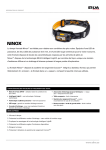
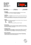
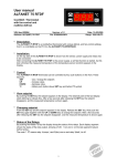
User manual ALFA-45A and ALFANET-45A SUPPLY-unit CPU-unit Cool/Defrost thermostat with Fan control and Watch Alarm. VDH doc. 053775 Software: ALFA 45A Version: v1.1 Doc: Do053775.wpd Datum: 17-03-2006 Range: -50/+50C, per 1C * Installation. The ALFA(NET)-45A consist of two parts, a Supply-unit for rail-mounting and a CPU-unit for frontmounting (with operation buttons, display and alarm relay). These two units are connected with each other by an cable with 8-pole data-connector. On the front of the ALFA-45A Modulbox supply-unit is shown how sensors, power supply and relay are to be connected. The watch alarm relay with C/NC contact is to be connected on the CPU-unit. After connecting the ALFA(NET)-45A to the power supply, a self test is started. As this test is finished the measured temperature of the product-sensor appears in the display. The Supply-unit has three relay outputs, one for the compressor, one for the fan and one for defrost. The compressor-relay and the defrost-relay got there own led-indication in the display. And the ALFANET -45A is by use of the ALFANET PC-INTERFACE controllable on the PC. * Control. The ALFA(NET)-45A thermostat can be controlled by three pushbuttons on the front. These keys are: SET - view / change of settings. UP - increase of settings. DOWN - decrease of settings. 1 * Viewing setpoint. By pushing the SET key the setpoint appears in the display. The led ‘set’ starts blinking. A few seconds after releasing the SET key the setpoint disappears and the measured product temperature is shown in the display. * Changing setpoint. Push the SET key and the setpoint appears in the display. Release the SET key. Now push the SET key again and together with the UP or DOWN keys the setpoint can be changed. A few seconds afer releasing the keys the measured product temperature is shown again in the display. * Manual starting/stopping of defrost. The defrost cycle is automatic started and stopped. These defrost settings thru internal parameters. At active defrost the led 'defrost' is on. Stop defrost: If there is a defrost cycle, the defrost can by manually stopped by pushing the UP key and than the SET key, while the UP key is hold. Start defrost: If there is no defrost cycle, the defrost can be started manually by pushing the UP key and than the SET key, while the UP key is hold. * Setting internal parameters. Next to the adjustment of the setpoint, some internal settings are possible like differential, sensoroffset, setpoint range and the defrost function. By pushing the DOWN key more than 10 seconds, you enter the 'internal programming menu'. In the left display the upper and lower segment are blinking. Over the UP and DOWN keys the required parameter can be selected (see table for the parameters). If the required parameter is selected, the value can be read-out by pushing the SET key. Pushing the UP and DOWN keys allows you to change the value of this parameter. If after 20 seconds no key is pushed, the ALFA(NET)-45A changes to it's normal operation mode. 2 * Parameters ALFA(NET)-45A. PARAMETER DESCRIPTION PARAMETER RANGE 01 02 03 04 Switching differential Minimum temperature alarm Maximum temperature alarm Offset product sensor 1..15C -50..+50C -50..+50C -15..+15C 05 Compressor start-up protection 0 = start-up delay in sec. 1 = start-up delay in min. 2 = delay between switch off and switch on in min. 3 = delay between switch on and switch on in min. Compressor start-up time belonging to parameter 05 0..3 0 0..99 10 1..99 hrs. 0..99 min. -99..+99C -99.+99C 0..99 min. 0..99 min. 0..99C 0..99 min. 12 15 2 2 0 0 2 0 15 Defrost interval Maximum defrost time End of defrost temperature Fan on temperature (P21=1) Fan delay time (P21=1) Drain time in min. Switching differential fan (P20=1) Defrost delay after power failure when parameter P27=1 Startup delay after power failure 0..99 min. 0 16 17 18 19 Offset defrost sensor Fan-off delay if parameter P23=1 Alarm delay Readout defrost sensor -15..+15C 0..99 min. 0..99 min. temp. in C 0 0 0 - 20 21 Fan switch differential active Fan off while defrost active 0=No, 1=Yes 0=No, 1=Yes 0 0 22 23 24 Compressor on at defrost Compressor off -> Fan off Compressor on at product sensor failure 0=No, 1=Yes 0=No, 1=Yes 0=No, 1=Yes 0 0 0 25 Defrost cycle time based on compressor running time Temperature display locked during defrost cycle Start with defrost after power failure 0=No, 1=Yes 0 0=No, 1=Yes 0 0=No, 1=Yes 0 Network number Software version Production year Production week Serial number (x1000) Serial number (units) 1..250 - 1 - 06 07 08 09 10 11 12 13 14 26 27 90 95 96 97 98 99 3 STANDARD VALUE 3 -50 +50 0 * Compressor control. The compressor relay activates when the product sensor measures a higher temperature than the setpoint + switching differential (parameter 1), and deactivates when the temperature descents below setpoint. There are 4 different modes off delay on the compressor possible with parameter 05 as shown below; Parameter 05 = 0 : The compressor relay has a start-up delay of "parameter 6" seconds. Parameter 05 = 1: The compressor relay has a start-up delay of "parameter 6" minutes. Parameter 05 = 2 : After switching off the compressor waits at least "parameter 6" minutes before switching on again. Parameter 05 = 3 : In between the switching-on points the compressor waits at least "parameter 6" minutes. Next options for Compressor control are available. Parameter 15 : A compressor on delay after power failure of "parameter 15" minutes. Parameter 24 =1: The compressor relay activates at product sensor failure. * Fan control. The ALFA(NET)-45A has several parameters for fan control. Normally the fan is always active, accept for one of the following parameters is set to 1, the fan can be stopped. Parameter 20 = 1 (Fan switch differential active): The fan is only active when the defrost temperature is "parameter 13" C lower then the measurement of the product temperature. As there are no further conditions to switch the fan off. (e.g. Parameter 13 = 2C and the product sensor measures 10C, than the fan is only active as the defrost sensor measures 10-2=8C or less.) Parameter 21 = 1 (Fan off on defrost cycle): The fan is switched off during defrost and to prevent blowing in hot air in the cabin after defrost and the dripping-off time, there are two conditions which can be set; 1: The fan is blocked until the defrost sensor measures a temperature lower than the temperature setting of parameter 10. 2: The fan is blocked until the defrost-delay-time of parameter 11 has stopped. Unless the defrost sensor has reached the temperature setting of parameter 10. When the defrost sensor is broken (Failure E2) the ALFA(NET)-45A runs down the entire time of parameter 11. Parameter 23 = 1 (Compressor off -> Fan off): The fan deactivates as the compressor deactivates, with a delay of "parameter 17" minutes. Provided that there are no other conditions to deactivates the fan. 4 * Defrost control. The automatic defrost is started by the defrost cycle time (P07) and stopped by the maximum defrost time (P08) or sooner by reaching the maximum defrost temperature (P09). Further has the ALFA(NET)-45A additional parameters to control defrost; Parameter 25 = 0: Function defrost with a fixed defrost cycle time. With parameter 7 as the chosen cycle time. Parameter 25 = 1: Function defrost based on total compressor running hours. The defrost is started when the compressor has run for parameter 7 hours after the last defrost. Parameter 26 = 1: The temperature readout on the display is locked during defrost cycle. Parameter 27 = 1: After power-up the ALFA(NET)-45A starts with defrost after running thru the defrost delay time of parameter 14. While running down the delay the ALFA(NET)-45A can cool, after this delay the defrost is started. Parameter 22 = 1: On hot gas systems the compressor is switched on during defrost. After defrost the dripping-off time of parameter 12 is started. During this time the defrost and compressor relay are deactivated, so the condenser can drip off it’s water. * Sensor adjustment. The product sensor (Temp.) can be adjusted by using the Offset product sensor parameter 04. The defrost sensor (Defr.) can be adjusted by using the Offset defrost sensor parameter 16. For readout of the defrost sensor on the display use parameter 19. Indicates a sensor e.g. 2C to much, the according Sensor Offset has to de decreased with 2C. 5 * Alarms. In the display of the ALFA(NET)-45A the following error messages can appear: E1 - Product sensor error E2 - Defrost sensor error E3 E4 Fatal error, display shows 'E1' and all relays are deactivated, accept when parameter 24 is 1, then the compressor and fan are activated as needed. Non fatal error, the ALFA(NET)-45A goes on regulating and the display shows 'E2'. - Maximum temperature alarm report - Minimum temperature alarm report Solution for E1 and/or E2: - Check if the sensor is connected correctly. - Check the according sensor (1000/25C). - Replace according sensor. EE Fatal error, settings are lost and display shows 'EE'. - Settings are lost Solution for EE: - Reprogram the settings. * Alarm Function. The ALFA(NET)-45A has a minimum alarm (P02) setting and a maximum alarm (P03) setting. When the temperature is beyond these limits the display shows E3 (maximum alarm) or E4 (minimum alarm) immediately. The alarm delay (P18) is also started and as the alarm is still on after the delay, the alarm relay will be deactivated (C/NC contact is closed). Normally (no alarm and power on controller) the alarm relay is activated (C/NC contact is open). The alarm will not be stored. 6 * Technical details. Types : ALFA-45A Cool/Defrost Thermostat with fan control ALFANET-45A Cool/Defrost Thermostat with fan control and RS485-network connection CPU-unit of the ALFA(NET)-45A Range : -50/+50C, readout per 1C Display : 3-digit 7-segment display Control : pushbuttons on the front. Status LEDs : 1xLED 'compr.', 1xLED 'set' and 1xLED 'defrost' Alarm-relay : SPST 250/8A (C-NC) (cos phi=1) Relay normally active, the C/NC contact is open and at alarm the C/NC contact is closed. Communication : ALFANET RS485-Network (3-wire shielded cable min. 0,75mm2) Only at ALFANET 45-A Front : Polycarbonate Sizes CPU-unit : 35 x 77 x 71,5mm (hwd) Panel cutout CPU-unit : 28 x 70mm (hw) SUPPLY-unit of the ALFA-45A Supply : 230 Vac 50/60Hz Max. used power : 6,2 VA Fuse : No internal fuse present Product sensor : SM 811/2m. Defrost sensor : SM 811/2m. Relay Compressor : SPST 250V/ 16A(C-NO) (cos phi=1) Relay Defrost : SPST 250V/8A(C-NO) (cos phi=1) Relay Fan : SPST 250V/8A(C-NO) (cos phi=1) Sizes Supply-unit : 58x71x90mm (hwd) for rail mounting Operation temperature : 0/+50C Operation rel. humidity : 10/90 %RH not condensing Ventilation : Keep ventilation holes open - Provided with memory protection during power failure. - Connection with screw terminals. - Equipped with self test function and sensor failure detection. - Special version on request available. * Address. VDH Products BV Produktieweg 1 9301 ZS Roden The Netherlands Tel: Fax: Email: Internet: 7 +31 (0)50 30 28 900 +31 (0)50 30 28 980 [email protected] www.vdhproducts.nl * Dimensions CPU-unit. * Dimensions SUPPLY-unit. * Connections. 8