1
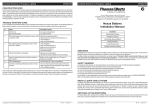
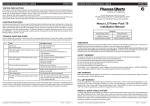
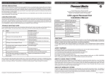
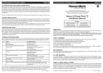
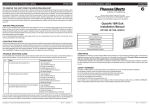
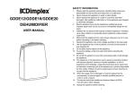
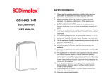
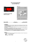
ISO 9001
Nexus RF User Guide
Chapter 1
Nexus RF System Structure
Doc No: 29-00001 (Chapter 1)
Table of Contents
What makes up a Nexus RF System?
Page 2
Nexus RF FittingsPage 2 - 5
Area Controllers and RoutersPage 5 - 7
Nexus RF Mesh NetworkPage 7
IP BackbonePage 7 - 8
Nexus RF Repeaters and AntennaePage 8
System GroupsPage 8 - 9
System ReportsPage 9 - 10
System IDPage 10
Site DocumentationPage 10 - 12
1
What makes up a Nexus RF System?
•
Nexus RF Fittings
•
Area Controllers and Routers
•
Nexus RF Mesh Network
•
IP Backbone
•
Nexus RF Repeaters and Antennae
•
System Groups
•
System Reports
•
System ID
•
Site Plans
•
Site Documentation
Nexus RF Fittings
Most Stanilite® exit signs, emergency luminaires, battens and flood lights will be available in Nexus® RF capable
models. This will include the market leading Quickfit® range of exit signs, Spitfire® series of emergency luminaires
and our LED product range.
LED Quickfit Exit
Building on the outstanding reliability of its predecessors in the Quickfit range, the Excel LED Quickfit employs
PerpetuLED® technology offering unsurpassed light source performance and longevity. Coupled with PulseTIME®
control of battery charging, which maximises battery life, the result is exceptional efficiency. Compatible with
existing Quickfit mounting brackets and available in a frame-only configuration which will accept existing Quickfit
diffusers, upgrading of existing installations to the latest technology is both simple and cost effective. As you would
expect from any Stanilite fitting, the Excel LED Quickfit comes with high quality electronic components offering the
best performance and value.
LED Spitfire Recessed
The Stanilite Excel LED Spitfire Recessed has been designed to provide high visibility whilst remaining
architecturally pleasing with a modern and unobtrusive design. As you would expect from any Stanilite fitting,
the Excel LED Spitfire Recessed comes with high quality electronic components offering the best performance
2
and value. There are single and dual LED fittings available, ensuring you have a product for all applications. Also
available in Surface Mount and Weatherproof Surface Mount.
LED Spitfire Batten
Incorporating two Stanilite dual-LED Spitfire fittings, the Spitfire batten delivers proven performance and
outstanding illumination with D100 emergency classification in both axes. High quality electronic components
used in manufacture offer the best possible performance and reliability. The Spitfire batten is also available for
maintained operation, ensuring that all application requirements are met.
Premium Batten
The Stanilite PRBT premium series of battens are available in Nexus RF configurations. The batten body is of white
powder coated steel, creating a tough and durable luminaire. Available in both T5 and T8 types, premium quality
electronic control gear is used across the range. Optional acrylic prismatic diffusers and white powder coated
galvanised wire guards are available, meeting the requirements for a broad range of applications. High temperature
NiCad batteries are used for optimal reliability.
Premium Weatherproof Batten
The Stanilite WPB series of weatherproof battens are available in Nexus RF configurations. Both the batten body
and diffuser are manufactured from polycarbonate which coupled with stainless steel diffuser clips, make a tough
and durable luminaire. Covering both T5 and T8 types, electronic control gear is used across the range.
LED Flood Light and LED Weatherproof Flood Light
The Excel LED Flood Light and Excel LED Weatherproof Flood Light incorporate twin 10W LED lamp heads, these
fittings provide outstanding photometric performance for area emergency lighting. Utilising the quality electronics
that are synonymous with the Stanilite brand, the Excel LED Flood Light is powered by a sealed lead acid battery
housed in a white powder coated zinc steel case. The Excel LED Weatherproof Flood Light is powered by a sealed
acid battery housed in a polycarbonate enclosure and has an IP65 protection rating.
For further information on our range of Nexus RF products, see the Stanilite Short Form Catalogue; http://www.tnb.ca/aus/pdfs/Stanilite-Short-Form-Catalogue.pdf
Emergency Lighting Test
According to AS/NZ2293, an emergency luminaire installed in a building must be tested every 6 months. The test
consists of removing the power to the battery charge circuit and monitoring the status of the emergency lamp. In
its first test a fitting must run with the emergency lamp lit for at least 120 minutes. In subsequent tests the fitting
must run for at least 90 minutes. Prior to the test the fitting must have been connected to the external power supply
continuously for at least 16 hours.
MAC Address
Each fitting has a unique hardware MAC address, eg: 4AF02. Each
fitting is supplied with a barcoded label indicating it’s MAC address. The
label includes a peel off component that needs to be collected during the
fitting installation. The MAC address is a crucial identifier for the fitting
during the fitting/system commissioning process.
3
SPU ID
When a fitting is commissioned it is given a SPU ID by the installer which is unique to that domain. Prior to being
commissioned the SPU ID of a unit is 0. The list of fittings, when displayed, is always sorted first by SPU ID then by
MAC so that a list of uncommissioned fittings is sorted by MAC address. The available SPU ID for commissioned
fittings is 1 - 65,000.
Fitting Information
The following information is stored within the fittings;
•
SPU ID
•
Part Number
•
MAC Address
•
Location Details
•
Group ID
•
Unit Status
•
Unit/Lamp/Battery Age
•
Test Results
•
System ID
Fitting LED Flashing Patterns
The LED on a fitting will flash according to its status. The table below describes the various states. The states are
prioritised; a state with high priority will take precedence over a state with low priority. For instance if a unit is under
test and therefore showing a red slow flash and is put into yellow blink at the same time, the LED will show the
yellow blink pattern since it has a higher priority.
4
Priority
Index
LED Pattern Description
State
1
13, 14 ,15
Yellow flash, 1 long 6 short
Configured and in flash yellow mode for
identification
2
0
Green very slow flash
Unconfigured
3
11
Red slow flash
Configured, not in yellow flash and
emergency test running
4
12
Green on steady
Okay and button pressed
4
1, 2, 3, 4, 5, 6 Green flash with 1 red blink
Configured but emergency hardware
fault
5
7
Green flash with 2 red blinks
Configured and hardware okay but unit
uncommissioned and no RF network
connection
5
8
Green flash with 3 red blinks
Configured and hardware okay and
RF network connection okay but unit
uncommissioned
5
9
Alternating green/red flash
Configured, commissioned and
hardware okay but no RF network
connection
5
10
Red on steady
Okay
Uncommissioned Fittings
Emergency luminaires are shipped from the factory with SPU ID = 0. A fitting with SPU ID = 0 is uncommissioned;
commissioning is the process of assigning a non-zero SPU ID to a fitting.
Area Controllers and Routers
Current Area Controller
The Area Controller (AC) is the system head-end controller. The Nexus RF system does
not require a PC to run the Nexus utilities, as has been the case in the past and still is with
competing products. The AC operates as a user interface as well as co-ordinating nodes both
through the associated system Routers and within its own mesh network.
Current Area Controller Router
NRFAC-E
The Area Controller Router (ACR) is used to expand the system beyond the capacity of an Area
Controller, for larger sites. The ACR monitors its own mesh independent of the Area Controller.
Should the Area Controller go off line or lose communications for any reason, the ACR will
continue to operate as normal and feedback information once the Area Controller becomes
available again.
New Area Controller
NRFACR-E
The new-generation Area Controller (AC) is physically different from its predecessor, the
touch-screen user interface rather than keypad and different shape being obvious changes.
Its function, however, remains unchanged when deployed in a Nexus RF system; it does not
require a connected computer running Nexus software or utilities, it utilises a website browser
interface as an alternative to the on-board graphical user interface (GUI) and it co-ordinates
nodes both through the Routers and its own mesh network.
New Area Controller Router
NAC-1 & NAC-2
The new generation Area Controller Router (ACR), as with the new Area Controller, is different
in appearance from its predecessor yet serves the same function when deployed in a Nexus
RF system. The ACR facilitates expansion of a network beyond the node capacity of the Area
Controller and is the means by which large systems are established. The ACR monitors its own
mesh independently of the Area Controller; should communication with the Area Controller be
lost, the ACR will function normally and will feed information back to the Area Controller once
communications are again established.
All Controllers
NACR-1
Each Controller can co-ordinate a mesh of up to 90 nodes and maintains a copy of the system database. All
Controllers are ethernet-capable and can be intermixed into a single system.
5
AC Interfaces
AC Interface (Old)
1
2
3
AC Interface (New)
4
5
6
ISSUE
A
Router Configurations
DATE
7
CHANGE
8
APPROVAL
ZONE
ECN
1
2
3
4
5
6
ISSUE
DATE
7
CHANGE
APPROVAL
A
Touch Screen for Power/Channel
Easy Control
Status LED’s
On/Off
Button
Wall
Mountable
B
B
C
C
D
12 VDC Plug
Pack
D
E
Ethernet Connection
100 MBPS
USB A and USB B ports for
connection to peripherals
such as keyboard, mouse,
modem, PC, etc
Diagnostics
Port
HEAT TREATMENT
MASS
RF EIM
Module
E
FINISH
Battery Backup
Module (Optional)
PART NO
MATERIAL
GRAMS
F
Router Configuration Parameters
APPROVED
DATE APPROVED
3RD ANGLE PROJECTION
TOLERANCES
DESCRIPTION
LINEAR� 0.50
HOLE CENTRES� 0.20
HOLE DIAMETERS� 0.10
ANGULAR� 0.5
ALL HOLE DIAMETERS
STATED ARE FINISHED
SIZES AFTER PLATING
(IF APPLICABLE)
Thomas & Betts Australiasia Pty Ltd
A Member of the ABB Group
23A Nyrang Street, Lidcombe NSW 2141 Australia
www.tnbaust.com
DRAWN BY : H.D DATE : Jul-14-14
AREA CONTROLLER - HOUSING BASE
DRAWING NUMBER
SCALE : 1:1
HEAT TREATMENT
MASS
GRAMS
WAMA013
F
SHEET : 3 OF 3
APPROVED
SIZE : A3
DATE APPROVED
3RD ANGLE PROJECTION
6
FINISH
N/A
N/A
TOLERANCES
MATERIAL
DESCRIPTION
LINEAR� 0.50
HOLE CENTRES� 0.20
HOLE DIAMETERS� 0.10
ANGULAR� 0.5
ALL HOLE DIAMETERS
STATED ARE FINISHED
SIZES AFTER PLATING
(IF APPLICABLE)
Thomas & Betts Australiasia Pty Ltd
A Member of the ABB Group
23A Nyrang Street, Lidcombe NSW 2141 Australia
www.tnbaust.com
DRAWN BY : H.D DATE : Jul-14-14
Parameter
Default
Description
Router ID
200
This is the unique ID assigned to a Router 1 - 255
Router Name
DEFAULT
Text description to identify a Router
System ID
1
The system ID is used to segregate Nexus RF systems in
proximity to each other 1 - 255
IP Address
10.224.5.200
Ethernet IP address
IP Subnet
255.255.255.0
Ethernet subnet
IP Gateway
10.224.5.1
Ethernet gateway address
AREA CONTROLLER
DRAWING NUMBER
SCALE : 3:10
WAMA
SHEET : 2 OF
AC/ACR Part Numbers
Part Number
Description
NAC-1
Nexus RF AC 1 x RF EIM (No Battery Module)
NAC-2
Nexus RF AC 1 x RF EIM (Battery Module)
NACR-1
Nexus RF ACR 1 x RF EIM
Replacement part numbers will be available via the relevant Technical Data Sheet, ie: EIM’s, battery modules, etc.
Nexus RF Mesh Network
A “network” is the group of luminaire controlled by an AC or ACR
referred to generically as Routers. The Nexus RF protocol uses
mesh networking to transfer messages between the Router and
all fittings in the network. This means that a particular Nexus RF
luminaire does not need to be able to communicate directly with
the Router - the message “hops” automatically from one luminaire
to the next to reach its final destination. The number of hops a
message must make is minimised automatically by the protocol.
When a Router is turned on it will attempt to form a network. Any
luminaires nearby that do not yet belong to a network will discover
the new network and attempt to join it. Other luminaires that may
not be in direct range of the new Router will now be able to join
this network through fittings that have joined it already. If a fitting
loses contact with its current network, it will search all the available
channel frequencies for a new network and will attempt to join the
first available network it finds.
Good design practice limits a network to 90 luminaires, however
the practical maximum is determined by site specific conditions.
Generally speaking the larger the number of luminaires in a
network, the more restricted is the data rate over the network.
The Nexus RF mesh network diagram shows an example of a
part of a Nexus RF system. The AC and ACR each control one
RF network. The connections shown between the various SPU’s
represents the mesh network; some luminaires have multiple
connections to other fittings, some fittings have direct connections to
the Router.
Nexus RF Mesh Network
IP Backbone
The Routers must all be connected to an IP backbone network. The preferred network type is an ethernet LAN
using standard Cat-5 data cable. If there is an existing LAN available, then with the permission of the network
administrator, each of the Routers can be connected to spare ports on the LAN. If there is no existing LAN,
or the administrator will not allow the connection of the system, then it will be necessary to install a dedicated
LAN. If there are only two AC/ACR devices, then they can be directly connected using a Cat-5 crossover cable.
7
Alternatively, two or more devices can be connected using an
ethernet hub or switch. In this case straight-through cables are
used. Note: there is a limit of about 100m for a run of Cat-5 cable.
A longer distance will require the use of additional ethernet hubs or
switches. The supply and installation of the ethernet backbone is
generally the responsibility of the installing contractor. It is essential
to ensure that the Cat-5 trunk cabling is installed in accordance with
the data cabling regulations.
Required Networking Ports
Rsync - Port 873
MySQL - 3306
AC/ACR WEB access - Port 80
AC/ACR SSH access - Port 22
The IP backbone diagram shows an example of a large Nexus
RF system with an ethernet LAN backbone. Each AC or ACR is
connected back to an ethernet switch port by a length of Cat-5 data
cable. In this case a PC is shown connected to the LAN. This is
optional and provides the user an alternative view of the system via
the website browser (Microsoft Internet Explorer) running on the PC.
Each Router (AC or ACR) controls its own network of RF fittings.
IP Backbone
Nexus RF Repeaters and Antennae
A repeater is used to boost the RF signal in difficult areas of the network. Few sites require the use of a repeater.
Remote antennae may be used to aide propogation of the RF signal if required.
System Groups
User Defined Groups
The group is the addressing mechanism to enable scheduled testing of emergency fittings. Groups are created as
required by the user. Groups have a group number and a group name. When a fitting first joins the network, it is
automatically added to a group with group number “0” and group name “default group”.
•
The system by default contains a single group, the default group which corresponds to group ID - 0.
•
By default all fittings are allocated to the default group.
•
The user can add or remove groups to or from the system as required to setup their required testing or
reporting structure.
•
Each user defined group consists of a group ID, group name and the fittings that are currently assigned to the
group.
•
All fittings are assigned to exactly one user defined group at any point in time.
•
The user can move the fittings from one group to another.
8
A typical scenario where multiple user defined groups are required,
is a small office building that has multiple tenants and the building
emergency lighting is managed by a seperate building management
group. In this case the building management group needs to be
able to seperately discharge test the tenants emergency fittings and
provide them with fault reports specific to their tenanted levels. If
the building was comprised of two seperate tenants, then a suitable
grouping solution would be as follows:
Group ID
Area
No fittings in this group
Group ID - 1 Common
Areas
All fittings in the common areas of
the building, ie: fire stairs, foyers,
basement levels
Group ID - 2 DHS Tenancy
All fittings belonging to the Ground
and L1 DHS levels
Group ID - 3 IBM Tenancy
All fittings belonging to the L2 IBM
level
Maintenance Group
The maintenance group is a virtual group used to collect all fittings
that either have a static fault or have failed their last diagnostic test
or discharge test. Faulty fittings are placed automatically in this
group and are removed automatically when the faults are cleared.
If a fitting has failed a previous discharge test and the problem that
caused the failure has been addressed, then the fitting should be
retested.
System Reports
•
Test Result Report
•
Work Instruction Report
•
Basic Work Instruction Report
9
DHS Tenancy
The 60 fittings belonging
to the DHS Tenancy, can
be allocated to:
Group 2 - DHS Tenancy
DHS Tenancy
The 180 fittings belonging
to the Base Building
Common Areas, can be
allocated to:
Group 1 - Base Building
L1 - 30
G - 30
Carpark - Common Area
B1 - 60
Carpark - Common Area
B2 - 60
Retest Group
The retest group is a virtual group used to collect all fittings that
require re-testing for some reason or because they failed to carry
out their last scheduled test. The retest group is scheduled in
the same way as a normal test group. Fittings are automatically
placed in the group if a scheduled test is not carried out. They are
automatically removed from the retest group if the test is completed
(whether test passed or failed). Units can also be manually placed in
the retest group and manually removed.
The 30 fittings belonging
to the IBM Tenancy, can
be allocated to:
Group 3 - IBM Tenancy
L2 - 30
Fittings
Group ID - 0 Default Group
IBM Tenancy
Carpark - Common Area
B3 - 60
An example of fitting group allocation based on
base building and tenanted areas
Test Results Report
Thomas&Betts Nexus RF
Emergency Lighting Test Result Report
24-07-2014, 10:54
Domain name: Lingard Hospital 3A
Address: Lingard st, Mereweather NSW
--------------------------------------------SPU_ID: 1
Unit Type: Spitfire
Group: 0, Default Group
Unit Description: SPITFIRE RF 1xLED N/M
Unit Part Number: SFNRF1LED
Unit MAC Address: 209FA
Test Status: Pass and Overdue
Date,Time,Result,Actual duration,Set duration,Pass limit,Batt charge,Termination
07-09-2013, 02:00,Pass,125:0,125,90,100 d 18 h 47 m,Time reached set limit
--------------------------------------------SPU_ID: 2
Unit Type: Spitfire
Group: 0, Default Group
Unit Description: SPITFIRE RF 1xLED N/M
Unit Part Number: SFNRF1LED
Unit MAC Address: 4019D
Test Status: Pass and Overdue
Date,Time,Result,Actual duration,Set duration,Pass limit,Batt charge,Termination
07-09-2013, 02:00,Pass,125:0,125,90,100 d 18 h 49 m,Time reached set limit
--------------------------------------------SPU_ID: 3
Unit Type: Spitfire
Group: 0, Default Group
Unit Description: SPITFIRE RF 1xLED N/M
Unit Part Number: SFNRF1LED
Unit MAC Address: 4019B
Test Status: Pass and Overdue
Date,Time,Result,Actual duration,Set duration,Pass limit,Batt charge,Termination
07-09-2013, 02:00,Pass,113:11,125,90,100 d 18 h 47 m,Battery voltage below
threshold
--------------------------------------------SPU_ID: 4
Unit Type: Spitfire
Group: 0, Default Group
Unit Description: SPITFIRE RF 1xLED N/M
Unit Part Number: SFNRF1LED
Unit MAC Address: 20A06
Test Status: Pass and Overdue
Date,Time,Result,Actual duration,Set duration,Pass limit,Batt charge,Termination
07-09-2013, 02:00,Pass,125:0,125,90,100 d 18 h 48 m,Time reached set limit
--------------------------------------------SPU_ID: 5
Unit Type: Spitfire
Group: 0, Default Group
Unit Description: SPITFIRE RF 1xLED N/M
Unit Part Number: SFNRF1LED
Unit MAC Address: 401B9
Test Status: Pass and Overdue
Date,Time,Result,Actual duration,Set duration,Pass limit,Batt charge,Termination
07-09-2013, 02:00,Pass,125:0,125,90,100 d 18 h 48 m,Time reached set limit
Page 1
Test Results Report
•
Offline Report
•
Maintenance History Report
•
Status Report
•
Location Report
•
Connection Report
System ID
The system ID provides a mechanism for two or more systems to sit side by side and yet remain separate. This
may be required when, for instance, a tenant in a shopping centre wants a separate system from that run by the
centre management.
If a system is configured for system ID “x”, then only luminaires configured with system ID “x” will be allowed to join
its RF mesh.
All Controllers and fittings leave production pre-configured to the default system ID of 1. The available range of
system ID’s is 1 - 255. A fittings system ID can be changed by accessing the fittings configuration via the AC’s
backdoor mode.
System ID - 2
System ID - 3
System ID - 1
The Nexus RF Mesh Network of the three separate buildings are effectively isolated
from each other by the allocation of unique System ID’s to each of the systems
Site Documentation
An emergency lighting system is not complete and is unmaintainable without the following system documentation:
•
As Built Site Plans.
•
Network System Diagram.
•
Fitting and Controller location details, site plan references and circuit breaker details entered into the system
database.
10
•
Fittings clearly labelled with their assigned SPU ID’s.
As Built Site Plans
The site plans should show the following information:
•
The fitting type and location.
•
The fittings allocated SPU ID (not the fitting MAC address).
•
The AC/ACR Controller locations.
•
The AC/ACR Router ID and IP address.
Network System Diagram
The network diagram should provide the following information:
•
An overview of the complete building network layout.
•
The install location for the AC/ACR Controllers, including floor or riser information.
•
The AC/ACR Controllers ID and IP address settings.
11
•
The location and type of the required supporting network hardware, ie: switches, CAT5/6 data cable.
•
The identification of any special remote antenna or coax cable installations.
12
Blank Page
13
Blank Page
14
Blank Page
© Thomas & Betts
(Australasia) Pty. Ltd. 2014
All technical claims in this document are based upon technical information available at the time
of publication. This information may change over time and comparisons may therefore vary.
Thomas & Betts (Australasia) Pty. Ltd. ABN 62 074 810 898
Head Office: Unit D3, 3-29 Birnie Avenue, Lidcombe NSW 2141, Australia
Manufacturing: 23a Nyrang Street, Lidcombe NSW 2141, Australia
Phone: 1300 666 595 │ Fax: 1300 666 594 │ Email: [email protected] │ Website: www.tnbaust.com
Rev: 1.0
8 October 2014